

Strobel ok, 441-2 User Manual

For the professional user
Mechanic‘s Instructions
Für den professionellen Anwender
Mechanikeranleitung
Class:
Klasse:
Dated:
Stand:
441-1 Ausf. 1
441-2 Ausf. 1
Spezialmaschinen GmbH

The sign of quality
ou nd the Strobel trademark on every Strobel
Y
machine leaving our works. And with good reason.
This symbol is a guarantee of the high quality of
our products. Quality which creates trust – trust
in our technology, our service and, not least of all,
in our good name.
Im Zeichen der Qualität
ie nden die Strobel-Schutzmarke auf jeder
S
Strobel-Maschine, die unser Werk verlässt.
Und das aus gutem Grund. Denn dieses Zeichen
garantiert Ihnen die hohe Qualität unserer
Produkte. Qualität, die Vertrauen schafft – in unsere
Technik, unseren Service und nicht zuletzt in unseren
guten Namen.

A decision with future
trobel clients know that they can expect a particularly
S
high standard of performance from our company and our
machines. Now you have settled for one of our products.
For us this is a source of encouragement and of obligation
to Justify your trust.
If you wish to prot from the performance and efciency of
your Strobel machine as long as possible, exact handling
and thorough care is necessary. For this reason we kindly
request that you read the operating instructions closely.
It provides all the information you need for trouble free
operation.
And if you do happen to need a spare part the enclosed
spare parts list gives a complete overview. It is clearly
classied according to components so that you can nd the
required part quickly and easily. In order to avoid errors we
request you to quote machine class, machine number and
part number completely on your spare part order.
We wish you lots of success in your work with your new
Strobel machine.
Spezialmaschinen GmbH


Mechanic’s instructions
STROBEL Class 441-1 and 441-2
Contents
1 General notes on safety ............................................................................................ 4
2 General notes ............................................................................................................ 6
2.1 Operating instructions ..................................................................................... 6
2.2 Class designations, machine number and initial basis for descriptions .......... 6
2.3 Applications of the machine use as intended ................................................. 6
2.4 Technical data ................................................................................................ 7
2.5 Abridged version of adjustment manual ......................................................... 8
3 Disassembly of the machine ................................................................................... 10
3.1 Disassembly of the front main shaft (Fig. 1 to Fig. 5) ................................... 10
4 Assembly of the machine ........................................................................................ 14
4.1 Assembly of the shaft (Fig. 4, Fig. 6 and Fig. 7) ........................................... 14
4.2 Assembly of the stitch variable eccentric (Fig. 4, Fig. 5, Fig. 6, Fig. 7) ......... 14
4.3 Setting the ecc. pin for stitch adjustment (Fig. 4 and Fig. 8) ........................ 15
4.4 Setting of the needle and transport movement ............................................. 16
4.5 The looper movement ................................................................................... 17
4.5.1 Setting the looper movement ........................................................... 17
4.5.2 Setting the looper eccentric .............................................................. 18
4.5.3 Setting the front crank ...................................................................... 19
4.5.4 Setting the front looper position to the feed cup .............................. 19
4.5.5 Setting the loop stroke ..................................................................... 19
4.5.6 Setting the rear bearing bracket ....................................................... 20
4.6 Height adjustment of the feed cup ................................................................ 20
4.7 Assembly of the front cup ............................................................................. 20
4.8 Tread lifting in the needle bar head .............................................................. 22
4.9 Spring tension at the plate bearing arm ........................................................ 22
4.9.1 Plate arm lifting ................................................................................ 22
4.10 Needle setting ............................................................................................... 23
4.10.1 Height adjustment of the needle (Fig. 13) ........................................ 23
4.11 Replacing the looper ..................................................................................... 24
4.12 Thread trimmer (optional) ............................................................................. 25
4.12.1 Calibration ........................................................................................ 25
1 MA_441-1-2_A1_180830_en

4.13 Positions ....................................................................................................... 26
4.14 Setting the positions ..................................................................................... 28
4.14.1 Setting the reference position .......................................................... 28
4.14.2 Setting the position 1 and 2 ............................................................. 29
4.14.3 Adjustment of the needle position for the use of our thread
trimmer ............................................................................................. 30
4.15 Display of the needle positions ..................................................................... 31
4.16 Sewing drive ................................................................................................. 31
4.17 Working with the control AB425 ................................................................... 32
4.17.1 Setting the stitch length .................................................................... 32
4.17.2 Working with operating control (V850) (Fig. 20) ............................... 33
4.17.3 Parameter und Functions F-714 (Class 441-2) ................................ 40
4.17.4 Parameter and Functions F-715 (Class 441-2) ................................ 42
4.17.5 Parameter and Functions F-760 (Class 441-2) ................................ 42
4.17.6 Copy sewing programs to another machines (Class 441-2) ............ 43
4.17.7 Brief instruction (Class 441-2) .......................................................... 44
4.18 Servicing the machine .................................................................................. 45
4.19 General notes ............................................................................................... 45
5 Notes on repair and adjustments ............................................................................ 46
5.1 Feed cup assembly ...................................................................................... 46
5.2 Replacing the feed cup ................................................................................. 46
5.2.1.1 Chain tension ................................................................... 47
5.3 Setting and installation instruction for the Strobel gathering device ............ 48
2 MA_441-1-2_A1_180830_en

Appendix
Circuit diagrams
Connecting the sewing ma chine:
258.10.27 Electrical wiring diagram AB425S Cl. 441-2 as of version 1
258.10.28 Electrical wiring diagram AB425S Cl. 441-2 as of version 1
258.30.28 Assembly plan AB425S Cl. 441-2 as of version 1
259.00.67 Pneumatic circuit diagram Cl. 441-2 as of version 1
259.10.67 Pneumatic construction circuit diagram Cl. 441-2 as of version 1
Strobel - Switchable functions
(DC1200-AB611A) Kl. 441-1
(DC1500-AB425S) Kl. 441-2
Strobel - Parameter list
(DC1200-AB611A) Kl. 441-1
(DC1500-AB425S) Kl. 441-2
Subject to change without prior notice
3 MA_441-1-2_A1_180830_en

1
General notes on safety
Every person in charge of setting up, operating, servicing and repairing the
machine must first read and understand the operating instructions and
particularly the safety instructions before starting up the machine.
Failure to comply with the following safety instructions can lead to bodily
injury or damage to the machine.
1. The machine must only be operated by persons familiar with the relevant
operating instructions and who have been instructed accordingly.
2. Before commissioning also read the notes on safety and the operating
instructions of the sewing drive manufacturer.
3. Only use the machine in the intended manner and never without the
provided guards. Always observe the pertinent safety regulations.
4. Switch off the main switch or pull the power plug for threading, changing
the reels, exchanging sewing tools such as needle, looper, needle plate,
transport devices, possibly cutter and cutting block, for cleaning and when
leaving the workplace as well as for maintenance.
5. General maintenance tasks may be carried out only by properly trained
persons in accordance with the operating instructions.
6. Repair work, retrofitting and maintenance may be carried out only by
technicians or specially trained personnel.
7. When servicing or repairing pneumatic equipment, the machine must be
disconnected from the pneumatic supply. Exceptions are only allowed for
adjustment work and tests of functionality performed by specially trained
technicians.
8. Only specially qualified technicians may work on the electrical equipment.
9. It is forbidden to work on electrically live components! Exemptions are
covered by the EN50110 (DIN VDE0105) regulations.
10. Any retrofitting or alterations to the machine may only be performed under
strict compliance with all pertinent safety regulations.
11. Only use our approved spare parts when servicing and/or repairing the
machine.
12. It is forbidden to operate the sewing head until it is determined that the
entire sewing unit complies with EU provisions.
13. It is essential that you observe and follow these instructions as well as the
generally valid safety regulations.
4 MA_441-1-2_A1_180830_en

14. Warning instructions given in the operating instructions that pertain to
especially dangerous parts of the machine must be indicated at these
positions using a safety symbol.
Warning instructions given in the operating instructions that pertain to
special injury hazards for operating personnel or technicians must be
indicated at these positions using a safety symbol.
5 MA_441-1-2_A1_180830_en

2
2.1
2.2
2.3
General notes
Operating instructions
Every person in charge of setting up, operating, servicing and repairing the
machine must first read and understand the operating instructions and
particularly the safety instructions before starting up the machine.
Class designati ons , machine number and initial basi s f or descriptions
The operating side of the machine is the initial basis for left/right descriptions.
The class type, machine and model number (after the dash) is attached in the
back of the housing.
Applications of the machine use as intended
Class 441-1
Single-thread overcast machine with gathering device for attaching soles to
shoes made of heavy textile material and leather up to a total thickness of 7
mm.
Class 441-2
Single-thread overcast machine for attaching soles to shoes made of heavy
textile material and leather up to a total thickness of 7 mm, with differential
drive.
6 MA_441-1-2_A1_180830_en

2.4
Technical data
Recommended nominal stitch number 1800 min-1
Belt pulley diameter/machine dw 80
V-belt profile 10 x 6 mm
Stitch length 3 – 8 mm
(depends on sewing material)
Stitch type single-thread overcast stitch
Stitch type 501
Needle system GROZ-BECKERT 134
Needle thickness 140
Thread polyester, continuously twined
Thread thickness 40
Transport type rear plate transport
Pneumatic connection 6 bar
Air consumption, average depends on equipment
Equipment footprint 0.6 x 1.06 m
Operating noise:
Averaged measuring surface sound pressure level
at stitch number n 1800 min
-1
Cl. 441-1 LpAm 71 dB
Cl. 441-2 LpAm 76.1 dB
Noise levels in acc. with DIN 45635-48-1 KL3
7 MA_441-1-2_A1_180830_en

Looper deflection to right from centre needle -
2.5
Abridged version of adjustment m a nua l
Setting value
Class
Needle type
Needle size
Stitch length
Loop stroke
Needle point front measured from plate edge
Needle bar eccentric stroke
Dimensio
n
A
B
C
E
134
120 - 140
3 - 8
5,5
24
32,4
looper point
Looper deflection to left
Looper position front measured from plate edge
Looper position rear
Looper transition
Looper height incl. shaft
Rear end position / Position without needle
Rear end position / Position with needle
F
G
H
J
K
L
M
N
4,9
10,2
11,7
6,2
10,5
37
about 48.5
about 9.4
8 MA_441-1-2_A1_180830_en
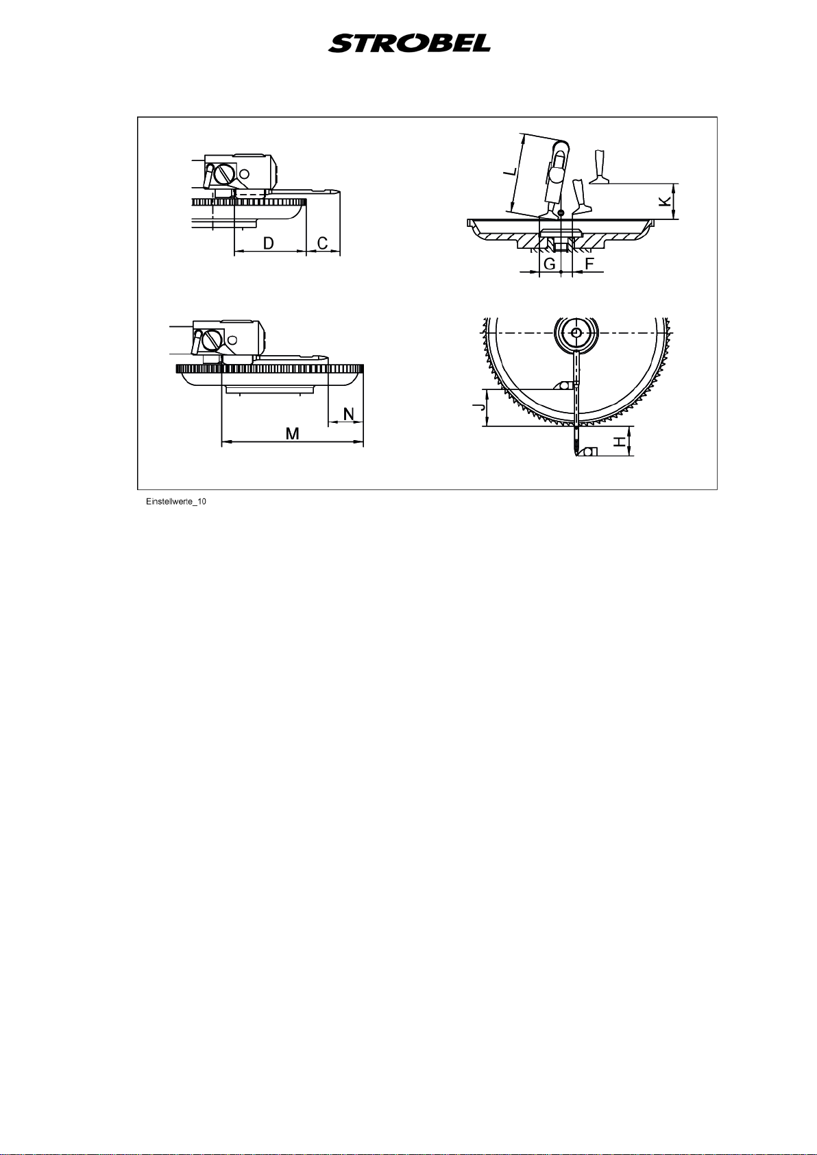
The lifting value between the feed cups is 12-14 mm.
9 MA_441-1-2_A1_180830_en
3
3.1
Disassembly of the machine
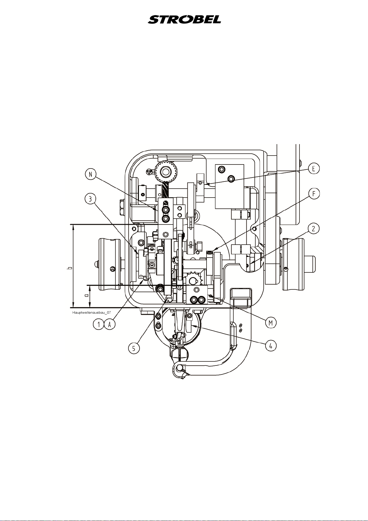
Disassembly of the front main shaft (Fig. 1 to Fig. 5)
Before beginning with disassembling the main shaft, it is recommended to
record all parts on the shaft using a ruler in a straight line. If necessary, starting
at the front edge of the stand, measure the distances of the front and rear
bearing bracket using a calliper and write them down
(dimension a + b).
This will save a lot of time during the assembly for calibration. (Fig. 4)
First of all, remove the right handwheel and then disassemble the belt guards in
the following sequence.
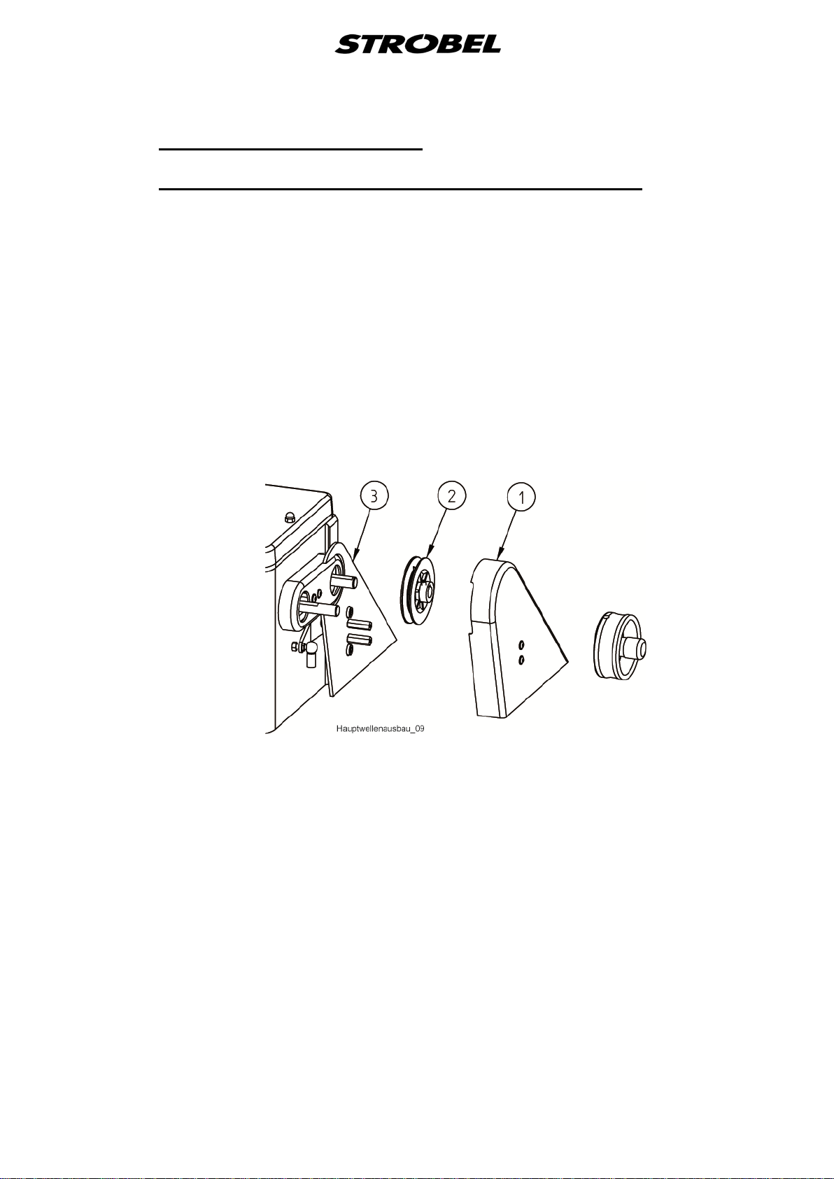
Cl. 441-1
The belt guard (1), the V-belt pulley (2) and the belt guard back wall (3). (Fig. 1)
Fig. 1
10 MA_441-1-2_A1_180830_en
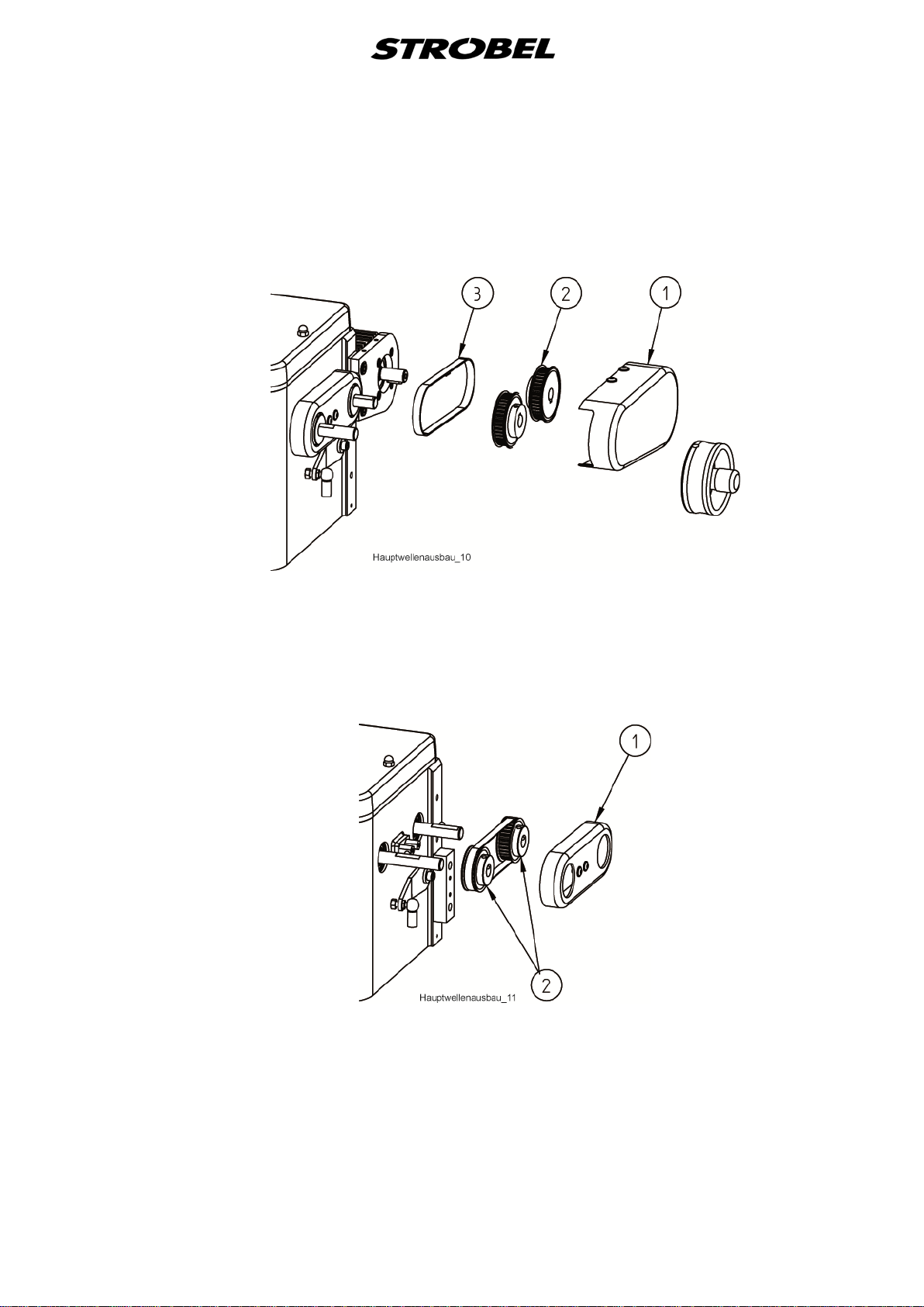
Cl. 441-2
The belt guard (1), the toothed belt pulleys (2) and the toothed belt (3).
(Fig. 2)
Fig. 2
Afterwards the belt guard (1). Now make a note of how the two toothed belt
pulleys (2) are mounted on the front and rear shaft. Now the toothed belt
pulleys (2) can be taken off with the toothed belt. (Fig. 3)
Fig. 3
The left handwheel with the stitch variable eccentric bolt does not need to be
removed. Make sure that the threaded pins (2) located on both sides of the
variable eccentric (A) (1) are removed.
(Fig. 4 and Fig. 5)
CAUTION! If not already done, mark the slideway (3) and variable
eccentric (A) (1) for correct installation position. (Fig. 5)
11 MA_441-1-2_A1_180830_en
Only then should the screws of the parts located on the shaft be loosened and
the shaft be pressed out to the left with an extracting tool.
Note here though that the shaft should be pressed to the left by about only
20-30 mm and the glue adhering to the shaft is removed; only then can the
shaft be pushed out all the way. Be careful that the ball bearings do not slip.
Any glue residues still on the shaft can be removed easily using a cleanser
(e.g. chloroethene).
Fig. 4
12 MA_441-1-2_A1_180830_en
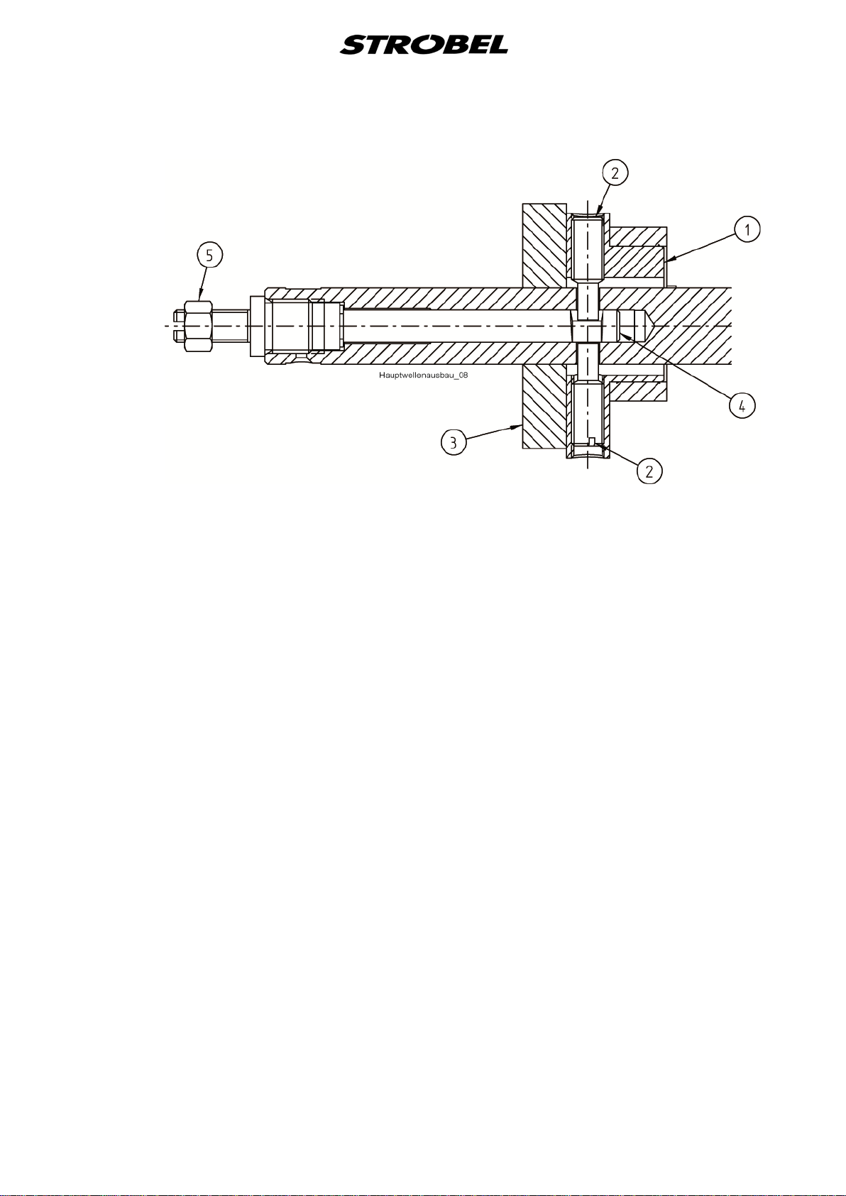
Fig. 5
13 MA_441-1-2_A1_180830_en

4
4.1
Assembly of the machine
Assembly of the shaft (Fig. 4, Fig. 6 and Fig. 7)
Once all parts have been in threaded in the correct sequence onto the shaft,
which has been cleaned of grease first, a drop of Loctite can be put each on
the shaft which still protrudes out to the left by about 30 mm, as well as on the
right part of the degreased shaft inside the machine stand, at the ball-bearing
seat. (Loctite, capillary 290)
CAUTION! To make a fault-free connection possible, the surfaces to be
joined must be completely grease-free. The shaft is then
pushed all the way into the stand, turned slightly so that the
Loctite is drawn in evenly all-around by the ball-bearing ring, the
stitch variable eccentric (A) (1) is fixated (see point "4.2
Assembly of the stitch variable eccentric"), the shaft is pushed
all the way to left and the adjusting ring (2) on the right shaft
side is sealed close so that the axial gap of the shaft is
removed. (Fig. 4)
After the adhesive has cured for about one hour (Loctite, capillary 290) the
machine can be assembled further and calibrated. During the repair assembly,
the left handwheel does not need to be taken off the shaft; however the control
knob (1) (Fig. 7) and the pins (3) and springs (2) do have to be removed (Fig.
6).
4.2
Assembly of the stitch variable eccentric (Fig. 4, Fi g. 5, Fig. 6, Fig. 7)
Mount the left handwheel on the installed shaft so that the tip of the first screw
fits, in the direction of rotation, into the depression of the left radial bore of the
shaft and stands upwards during that.
Turn the slideway (3) so that the variable eccentric (1) can be pushed down in
the position described above. (Fig. 5)
Turn the first screw (2) so far into variable eccentric so that the adjustment bolt
(4) can be turned through in the shaft. First, loosen the counter nut. Turn the
handwheel with shaft by 180°. Turn the second screw (2) all the way into
variable eccentric; the adjustment bolt (4) should be able to rotate free of
backlash. Screw slideway (3) onto the shaft. (Fig. 5)
Slide the shaft all the way to the left on the ball bearings, push adjusting ring (2)
on the right shaft side all the way on the ball bearings and tighten. The shaft is
fixated now. (Fig. 4)
Allow stitch variable eccentric (1) to level off and tighten. Slide two greased
springs (2) and two greased pins (3) into the bore of the handwheel (Fig. 6).
14 MA_441-1-2_A1_180830_en
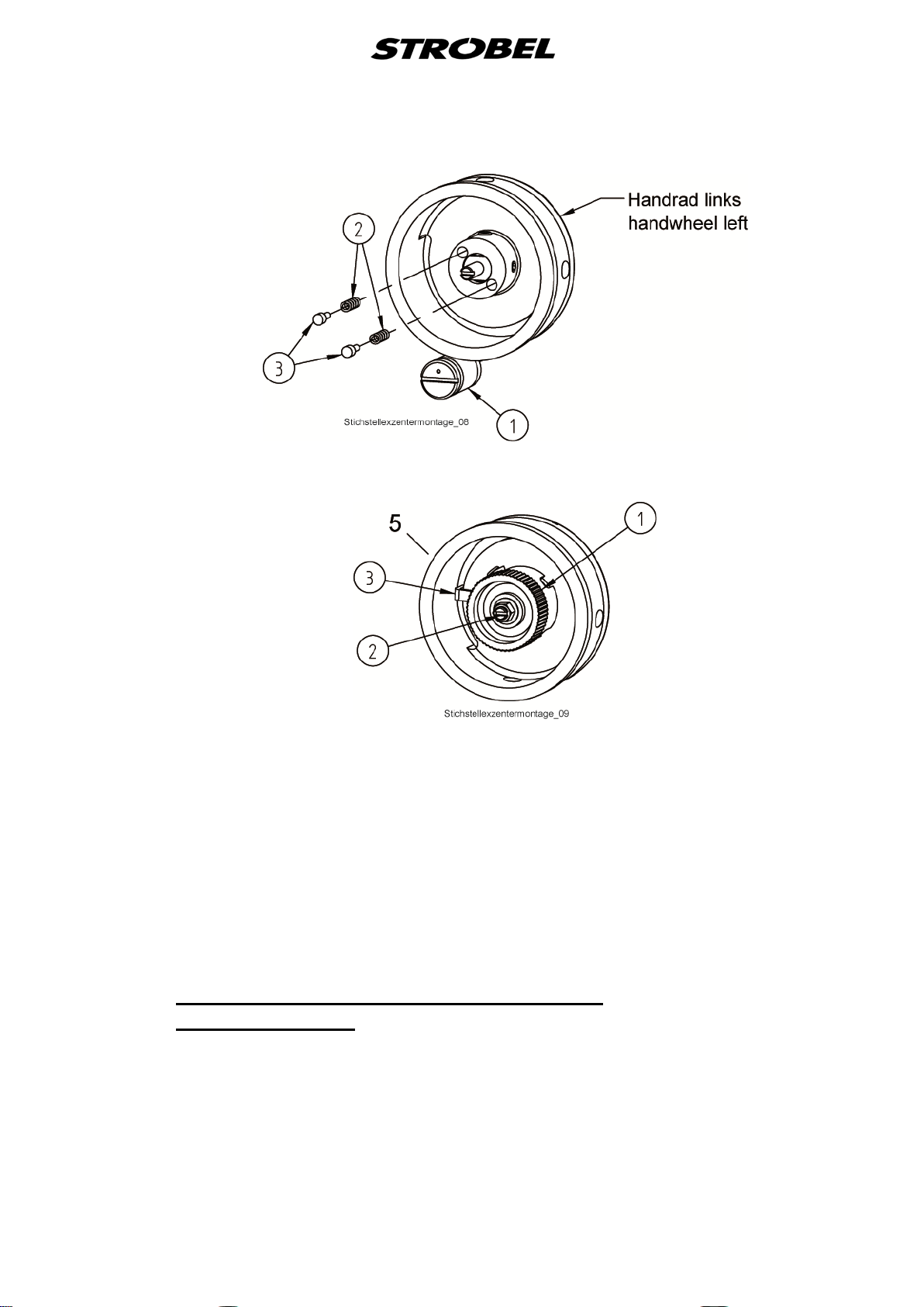
Fig. 6
Fig. 7
4.3
Screw the control knob (1) onto the shaft or the adjustment bolt (2) until the
control knob contacts the handwheel. Hold the control knob tight and screw out
the adjustment bolt until the pointer (3) on the control knob of the handwheel
(marking 5), (large stitch), contacts and can be slightly seen between
handwheel and stand. (Fig. 7)
The control knob needs to be free from the large to the small stitch.
If the setting has been done properly, the variable eccentric (1) is standing at
the large stitch at the top dead centre and the pointer of the control nut is at the
marking 5 on the handwheel. To complete, the counter nut (5) is screwed on.
(Fig. 5)
Setting the ecc. pin for stitch adj us t m e nt (Fig. 4 and Fig. 8 )
In combination with the stitch variable eccentric (A) (1) (
(1) needs to be set to the determined position for the stitch length specified for
each class (see "2.5 Abridged version of adjustment manual"). Please be sure
that the rocker (2) and the connecting rod (3) are not stretched out. The
marking (punch mark) made on the ecc. pin (1) (Fig. 6) has to be mounted
upwards in any case. This has the effect that the punch mark is swivelled to the
right (-) for a smaller stitch and to the left (+) for a larger stitch - arrow direction.
(Fig. 8)
Fig. 4), the ecc. pin (B)
15 MA_441-1-2_A1_180830_en
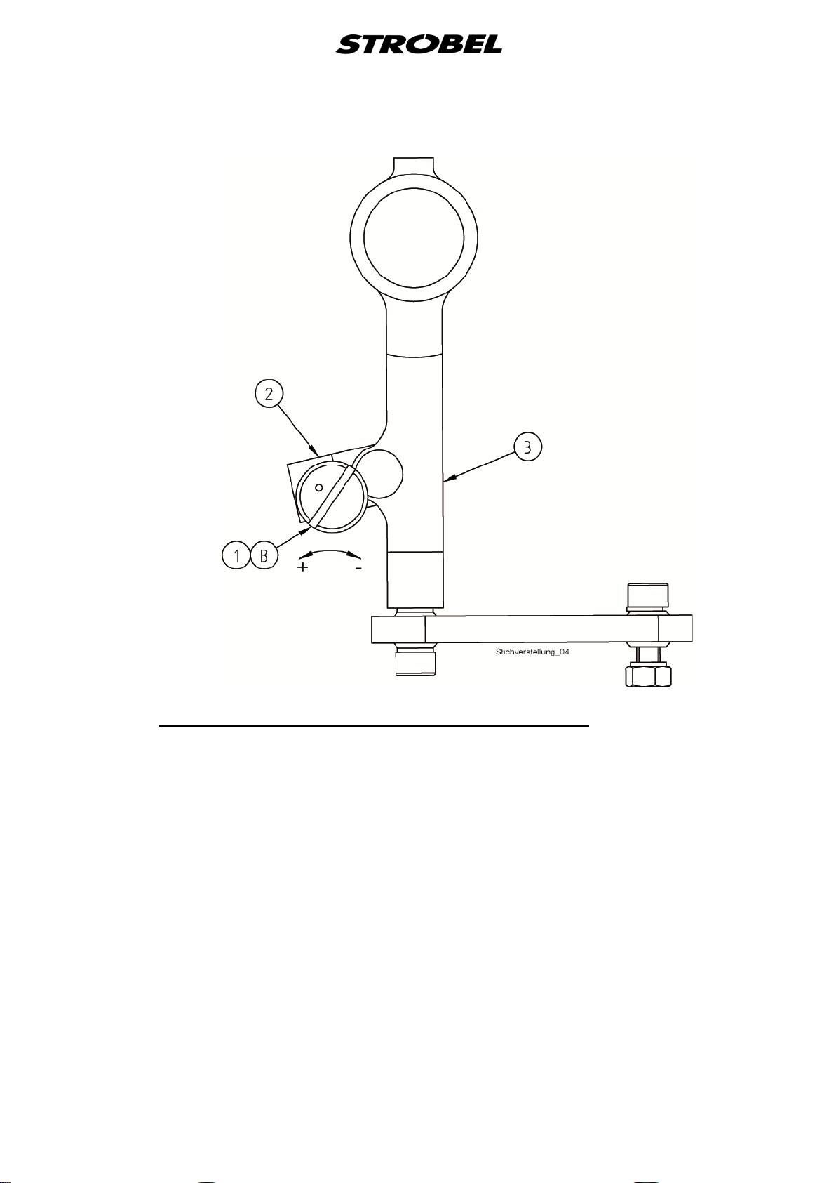
Fig. 8
4.4
Setting of the needl e a nd t ransport movement
If the largest stitch length is set (see "
manual"), the transport movement is ended when the needle point is located
about 1.5 mm within the plate edge before the piercing.
Transport beginning is when the needle has left the material and is located
about 1 mm behind the plate edge.
The setting is done at the needle bar eccentric (E) (Fig. 4); observe the frontmost needle position thereby (see "2.5 Abridged version of adjustment
manual").
During the setting of the needle bar, make sure that the surface on the needle
bar for needle clamping is precisely at a right angle to the feed cup.
2.5 Abridged version of adjustment
16 MA_441-1-2_A1_180830_en
 Loading...