


For the professional user
Mechanic‘s Instructions
Für den professionellen Anwender
Mechanikeranleitung
Class:
Klasse:
Dated:
Stand:
441-1 Ausf. 1
441-2 Ausf. 1
Spezialmaschinen GmbH

The sign of quality
ou nd the Strobel trademark on every Strobel
Y
machine leaving our works. And with good reason.
This symbol is a guarantee of the high quality of
our products. Quality which creates trust – trust
in our technology, our service and, not least of all,
in our good name.
Im Zeichen der Qualität
ie nden die Strobel-Schutzmarke auf jeder
S
Strobel-Maschine, die unser Werk verlässt.
Und das aus gutem Grund. Denn dieses Zeichen
garantiert Ihnen die hohe Qualität unserer
Produkte. Qualität, die Vertrauen schafft – in unsere
Technik, unseren Service und nicht zuletzt in unseren
guten Namen.

A decision with future
trobel clients know that they can expect a particularly
S
high standard of performance from our company and our
machines. Now you have settled for one of our products.
For us this is a source of encouragement and of obligation
to Justify your trust.
If you wish to prot from the performance and efciency of
your Strobel machine as long as possible, exact handling
and thorough care is necessary. For this reason we kindly
request that you read the operating instructions closely.
It provides all the information you need for trouble free
operation.
And if you do happen to need a spare part the enclosed
spare parts list gives a complete overview. It is clearly
classied according to components so that you can nd the
required part quickly and easily. In order to avoid errors we
request you to quote machine class, machine number and
part number completely on your spare part order.
We wish you lots of success in your work with your new
Strobel machine.
Spezialmaschinen GmbH


Mechanic’s instructions
STROBEL Class 441-1 and 441-2
Contents
1 General notes on safety ............................................................................................ 4
2 General notes ............................................................................................................ 6
2.1 Operating instructions ..................................................................................... 6
2.2 Class designations, machine number and initial basis for descriptions .......... 6
2.3 Applications of the machine use as intended ................................................. 6
2.4 Technical data ................................................................................................ 7
2.5 Abridged version of adjustment manual ......................................................... 8
3 Disassembly of the machine ................................................................................... 10
3.1 Disassembly of the front main shaft (Fig. 1 to Fig. 5) ................................... 10
4 Assembly of the machine ........................................................................................ 14
4.1 Assembly of the shaft (Fig. 4, Fig. 6 and Fig. 7) ........................................... 14
4.2 Assembly of the stitch variable eccentric (Fig. 4, Fig. 5, Fig. 6, Fig. 7) ......... 14
4.3 Setting the ecc. pin for stitch adjustment (Fig. 4 and Fig. 8) ........................ 15
4.4 Setting of the needle and transport movement ............................................. 16
4.5 The looper movement ................................................................................... 17
4.5.1 Setting the looper movement ........................................................... 17
4.5.2 Setting the looper eccentric .............................................................. 18
4.5.3 Setting the front crank ...................................................................... 19
4.5.4 Setting the front looper position to the feed cup .............................. 19
4.5.5 Setting the loop stroke ..................................................................... 19
4.5.6 Setting the rear bearing bracket ....................................................... 20
4.6 Height adjustment of the feed cup ................................................................ 20
4.7 Assembly of the front cup ............................................................................. 20
4.8 Tread lifting in the needle bar head .............................................................. 22
4.9 Spring tension at the plate bearing arm ........................................................ 22
4.9.1 Plate arm lifting ................................................................................ 22
4.10 Needle setting ............................................................................................... 23
4.10.1 Height adjustment of the needle (Fig. 13) ........................................ 23
4.11 Replacing the looper ..................................................................................... 24
4.12 Thread trimmer (optional) ............................................................................. 25
4.12.1 Calibration ........................................................................................ 25
1 MA_441-1-2_A1_180830_en

4.13 Positions ....................................................................................................... 26
4.14 Setting the positions ..................................................................................... 28
4.14.1 Setting the reference position .......................................................... 28
4.14.2 Setting the position 1 and 2 ............................................................. 29
4.14.3 Adjustment of the needle position for the use of our thread
trimmer ............................................................................................. 30
4.15 Display of the needle positions ..................................................................... 31
4.16 Sewing drive ................................................................................................. 31
4.17 Working with the control AB425 ................................................................... 32
4.17.1 Setting the stitch length .................................................................... 32
4.17.2 Working with operating control (V850) (Fig. 20) ............................... 33
4.17.3 Parameter und Functions F-714 (Class 441-2) ................................ 40
4.17.4 Parameter and Functions F-715 (Class 441-2) ................................ 42
4.17.5 Parameter and Functions F-760 (Class 441-2) ................................ 42
4.17.6 Copy sewing programs to another machines (Class 441-2) ............ 43
4.17.7 Brief instruction (Class 441-2) .......................................................... 44
4.18 Servicing the machine .................................................................................. 45
4.19 General notes ............................................................................................... 45
5 Notes on repair and adjustments ............................................................................ 46
5.1 Feed cup assembly ...................................................................................... 46
5.2 Replacing the feed cup ................................................................................. 46
5.2.1.1 Chain tension ................................................................... 47
5.3 Setting and installation instruction for the Strobel gathering device ............ 48
2 MA_441-1-2_A1_180830_en

Appendix
Circuit diagrams
Connecting the sewing ma chine:
258.10.27 Electrical wiring diagram AB425S Cl. 441-2 as of version 1
258.10.28 Electrical wiring diagram AB425S Cl. 441-2 as of version 1
258.30.28 Assembly plan AB425S Cl. 441-2 as of version 1
259.00.67 Pneumatic circuit diagram Cl. 441-2 as of version 1
259.10.67 Pneumatic construction circuit diagram Cl. 441-2 as of version 1
Strobel - Switchable functions
(DC1200-AB611A) Kl. 441-1
(DC1500-AB425S) Kl. 441-2
Strobel - Parameter list
(DC1200-AB611A) Kl. 441-1
(DC1500-AB425S) Kl. 441-2
Subject to change without prior notice
3 MA_441-1-2_A1_180830_en

1
General notes on safety
Every person in charge of setting up, operating, servicing and repairing the
machine must first read and understand the operating instructions and
particularly the safety instructions before starting up the machine.
Failure to comply with the following safety instructions can lead to bodily
injury or damage to the machine.
1. The machine must only be operated by persons familiar with the relevant
operating instructions and who have been instructed accordingly.
2. Before commissioning also read the notes on safety and the operating
instructions of the sewing drive manufacturer.
3. Only use the machine in the intended manner and never without the
provided guards. Always observe the pertinent safety regulations.
4. Switch off the main switch or pull the power plug for threading, changing
the reels, exchanging sewing tools such as needle, looper, needle plate,
transport devices, possibly cutter and cutting block, for cleaning and when
leaving the workplace as well as for maintenance.
5. General maintenance tasks may be carried out only by properly trained
persons in accordance with the operating instructions.
6. Repair work, retrofitting and maintenance may be carried out only by
technicians or specially trained personnel.
7. When servicing or repairing pneumatic equipment, the machine must be
disconnected from the pneumatic supply. Exceptions are only allowed for
adjustment work and tests of functionality performed by specially trained
technicians.
8. Only specially qualified technicians may work on the electrical equipment.
9. It is forbidden to work on electrically live components! Exemptions are
covered by the EN50110 (DIN VDE0105) regulations.
10. Any retrofitting or alterations to the machine may only be performed under
strict compliance with all pertinent safety regulations.
11. Only use our approved spare parts when servicing and/or repairing the
machine.
12. It is forbidden to operate the sewing head until it is determined that the
entire sewing unit complies with EU provisions.
13. It is essential that you observe and follow these instructions as well as the
generally valid safety regulations.
4 MA_441-1-2_A1_180830_en

14. Warning instructions given in the operating instructions that pertain to
especially dangerous parts of the machine must be indicated at these
positions using a safety symbol.
Warning instructions given in the operating instructions that pertain to
special injury hazards for operating personnel or technicians must be
indicated at these positions using a safety symbol.
5 MA_441-1-2_A1_180830_en

2
2.1
2.2
2.3
General notes
Operating instructions
Every person in charge of setting up, operating, servicing and repairing the
machine must first read and understand the operating instructions and
particularly the safety instructions before starting up the machine.
Class designati ons , machine number and initial basi s f or descriptions
The operating side of the machine is the initial basis for left/right descriptions.
The class type, machine and model number (after the dash) is attached in the
back of the housing.
Applications of the machine use as intended
Class 441-1
Single-thread overcast machine with gathering device for attaching soles to
shoes made of heavy textile material and leather up to a total thickness of 7
mm.
Class 441-2
Single-thread overcast machine for attaching soles to shoes made of heavy
textile material and leather up to a total thickness of 7 mm, with differential
drive.
6 MA_441-1-2_A1_180830_en

2.4
Technical data
Recommended nominal stitch number 1800 min-1
Belt pulley diameter/machine dw 80
V-belt profile 10 x 6 mm
Stitch length 3 – 8 mm
(depends on sewing material)
Stitch type single-thread overcast stitch
Stitch type 501
Needle system GROZ-BECKERT 134
Needle thickness 140
Thread polyester, continuously twined
Thread thickness 40
Transport type rear plate transport
Pneumatic connection 6 bar
Air consumption, average depends on equipment
Equipment footprint 0.6 x 1.06 m
Operating noise:
Averaged measuring surface sound pressure level
at stitch number n 1800 min
-1
Cl. 441-1 LpAm 71 dB
Cl. 441-2 LpAm 76.1 dB
Noise levels in acc. with DIN 45635-48-1 KL3
7 MA_441-1-2_A1_180830_en

Looper deflection to right from centre needle -
2.5
Abridged version of adjustment m a nua l
Setting value
Class
Needle type
Needle size
Stitch length
Loop stroke
Needle point front measured from plate edge
Needle bar eccentric stroke
Dimensio
n
A
B
C
E
134
120 - 140
3 - 8
5,5
24
32,4
looper point
Looper deflection to left
Looper position front measured from plate edge
Looper position rear
Looper transition
Looper height incl. shaft
Rear end position / Position without needle
Rear end position / Position with needle
F
G
H
J
K
L
M
N
4,9
10,2
11,7
6,2
10,5
37
about 48.5
about 9.4
8 MA_441-1-2_A1_180830_en

The lifting value between the feed cups is 12-14 mm.
9 MA_441-1-2_A1_180830_en

3
3.1
Disassembly of the machine
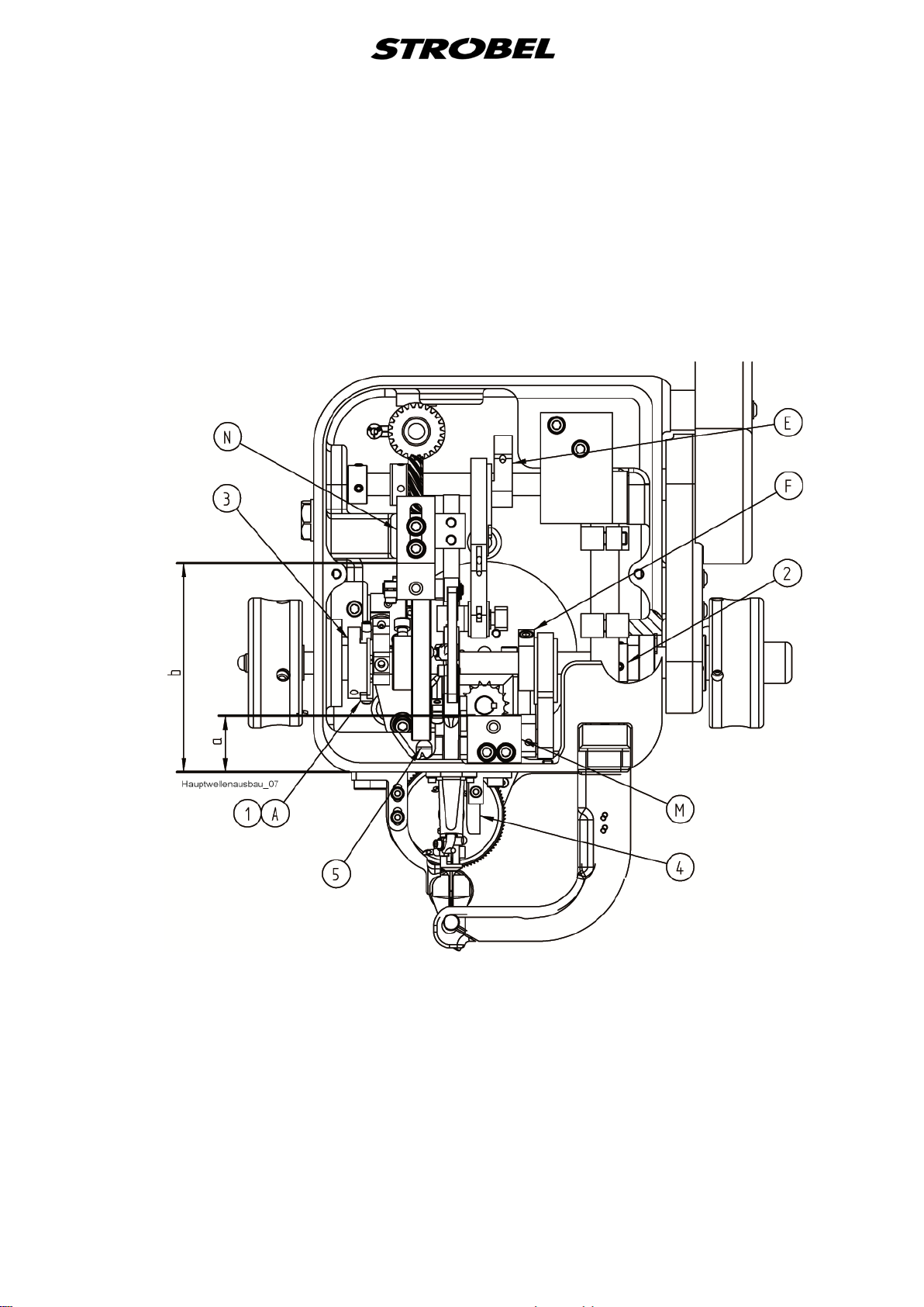
Disassembly of the front main shaft (Fig. 1 to Fig. 5)
Before beginning with disassembling the main shaft, it is recommended to
record all parts on the shaft using a ruler in a straight line. If necessary, starting
at the front edge of the stand, measure the distances of the front and rear
bearing bracket using a calliper and write them down
(dimension a + b).
This will save a lot of time during the assembly for calibration. (Fig. 4)
First of all, remove the right handwheel and then disassemble the belt guards in
the following sequence.
Cl. 441-1
The belt guard (1), the V-belt pulley (2) and the belt guard back wall (3). (Fig. 1)
Fig. 1
10 MA_441-1-2_A1_180830_en
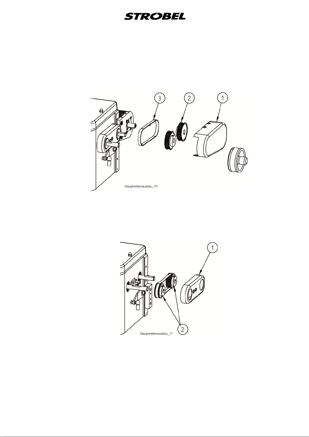
Cl. 441-2
The belt guard (1), the toothed belt pulleys (2) and the toothed belt (3).
(Fig. 2)
Fig. 2
Afterwards the belt guard (1). Now make a note of how the two toothed belt
pulleys (2) are mounted on the front and rear shaft. Now the toothed belt
pulleys (2) can be taken off with the toothed belt. (Fig. 3)
Fig. 3
The left handwheel with the stitch variable eccentric bolt does not need to be
removed. Make sure that the threaded pins (2) located on both sides of the
variable eccentric (A) (1) are removed.
(Fig. 4 and Fig. 5)
CAUTION! If not already done, mark the slideway (3) and variable
eccentric (A) (1) for correct installation position. (Fig. 5)
11 MA_441-1-2_A1_180830_en
Only then should the screws of the parts located on the shaft be loosened and
the shaft be pressed out to the left with an extracting tool.
Note here though that the shaft should be pressed to the left by about only
20-30 mm and the glue adhering to the shaft is removed; only then can the
shaft be pushed out all the way. Be careful that the ball bearings do not slip.
Any glue residues still on the shaft can be removed easily using a cleanser
(e.g. chloroethene).
Fig. 4
12 MA_441-1-2_A1_180830_en

Fig. 5
13 MA_441-1-2_A1_180830_en

4
4.1
Assembly of the machine
Assembly of the shaft (Fig. 4, Fig. 6 and Fig. 7)
Once all parts have been in threaded in the correct sequence onto the shaft,
which has been cleaned of grease first, a drop of Loctite can be put each on
the shaft which still protrudes out to the left by about 30 mm, as well as on the
right part of the degreased shaft inside the machine stand, at the ball-bearing
seat. (Loctite, capillary 290)
CAUTION! To make a fault-free connection possible, the surfaces to be
joined must be completely grease-free. The shaft is then
pushed all the way into the stand, turned slightly so that the
Loctite is drawn in evenly all-around by the ball-bearing ring, the
stitch variable eccentric (A) (1) is fixated (see point "4.2
Assembly of the stitch variable eccentric"), the shaft is pushed
all the way to left and the adjusting ring (2) on the right shaft
side is sealed close so that the axial gap of the shaft is
removed. (Fig. 4)
After the adhesive has cured for about one hour (Loctite, capillary 290) the
machine can be assembled further and calibrated. During the repair assembly,
the left handwheel does not need to be taken off the shaft; however the control
knob (1) (Fig. 7) and the pins (3) and springs (2) do have to be removed (Fig.
6).
4.2
Assembly of the stitch variable eccentric (Fig. 4, Fi g. 5, Fig. 6, Fig. 7)
Mount the left handwheel on the installed shaft so that the tip of the first screw
fits, in the direction of rotation, into the depression of the left radial bore of the
shaft and stands upwards during that.
Turn the slideway (3) so that the variable eccentric (1) can be pushed down in
the position described above. (Fig. 5)
Turn the first screw (2) so far into variable eccentric so that the adjustment bolt
(4) can be turned through in the shaft. First, loosen the counter nut. Turn the
handwheel with shaft by 180°. Turn the second screw (2) all the way into
variable eccentric; the adjustment bolt (4) should be able to rotate free of
backlash. Screw slideway (3) onto the shaft. (Fig. 5)
Slide the shaft all the way to the left on the ball bearings, push adjusting ring (2)
on the right shaft side all the way on the ball bearings and tighten. The shaft is
fixated now. (Fig. 4)
Allow stitch variable eccentric (1) to level off and tighten. Slide two greased
springs (2) and two greased pins (3) into the bore of the handwheel (Fig. 6).
14 MA_441-1-2_A1_180830_en

Fig. 6
Fig. 7
4.3
Screw the control knob (1) onto the shaft or the adjustment bolt (2) until the
control knob contacts the handwheel. Hold the control knob tight and screw out
the adjustment bolt until the pointer (3) on the control knob of the handwheel
(marking 5), (large stitch), contacts and can be slightly seen between
handwheel and stand. (Fig. 7)
The control knob needs to be free from the large to the small stitch.
If the setting has been done properly, the variable eccentric (1) is standing at
the large stitch at the top dead centre and the pointer of the control nut is at the
marking 5 on the handwheel. To complete, the counter nut (5) is screwed on.
(Fig. 5)
Setting the ecc. pin for stitch adj us t m e nt (Fig. 4 and Fig. 8 )
In combination with the stitch variable eccentric (A) (1) (
(1) needs to be set to the determined position for the stitch length specified for
each class (see "2.5 Abridged version of adjustment manual"). Please be sure
that the rocker (2) and the connecting rod (3) are not stretched out. The
marking (punch mark) made on the ecc. pin (1) (Fig. 6) has to be mounted
upwards in any case. This has the effect that the punch mark is swivelled to the
right (-) for a smaller stitch and to the left (+) for a larger stitch - arrow direction.
(Fig. 8)
Fig. 4), the ecc. pin (B)
15 MA_441-1-2_A1_180830_en

Fig. 8
4.4
Setting of the needl e a nd t ransport movement
If the largest stitch length is set (see "
manual"), the transport movement is ended when the needle point is located
about 1.5 mm within the plate edge before the piercing.
Transport beginning is when the needle has left the material and is located
about 1 mm behind the plate edge.
The setting is done at the needle bar eccentric (E) (Fig. 4); observe the frontmost needle position thereby (see "2.5 Abridged version of adjustment
manual").
During the setting of the needle bar, make sure that the surface on the needle
bar for needle clamping is precisely at a right angle to the feed cup.
2.5 Abridged version of adjustment
16 MA_441-1-2_A1_180830_en

4.5
4.5.1
The looper movement
The looper movement is determined by the stroke of the looper eccentric (F)
(
Fig. 4) or (1) (Fig. 9), by the crank distance and by the bore distance of the
clamping lever (2) (Fig. 9). The looper movement has to equal temporally the
needle bar movement.
The curve form of the control curve (3) (Fig. 9) produces the lateral looper
deflection, corresponding to the needle movement.
Make sure that the looper carriage (4) (Fig. 9) or the looper shaft is mounted
exactly centrally to the needle bar (5) (Fig. 9).
It is recommended for setting the parts described below to mount them on the
shaft so that they adhere, but can still be turned by hand and then tightening
them after the final setting.
Setting the looper movement
Find the top dead centre of the needle bar eccentric and mark it(corresponds to
position "1"). (E) (
The top dead centre of the needle bar eccentric equals the bottom dead centre
offset by 180° of the looper eccentric (1) (Fig. 9) (see point "4.5.2 Setting the
looper eccentric").
Fig. 4)
Turn the control curve (3) in this position until the leftwards movement of the
looper reaches the reversal point after taking up the loop.
(Fig. 9)
Make sure that the control curve (3) is fixated so that there is a backlash of
about 1 mm between curve and adjusting ring on the looper carriage (4) (Fig.
9). The looper deflection is influenced by a lateral shifting of the control curve
(3).
If the distance is enlarged, this results in a smaller looper deflection to the right.
The total path of the looper changes insignificantly.
17 MA_441-1-2_A1_180830_en

Fig. 9
4.5.2
Setting the looper eccentric
Set the looper eccentric (1) (at position "1") so that its surface is horizontal (
9). During a later partial rotation of about 100° at the handwheel (position "2"),
the back-most needle position is reached. The looper is positioned then about 2
mm left of and about 3 mm over the needle, differently depending on the loop
stroke (Fig. 10a). During forwards movement of the needle, the needle point
arrives then at the right looper edge, whereby the needle point stands about 1
mm over the looper and then moves over the looper at an unvarying distance
(Fig. 10b). The needle point is located at the rear dead centre of the looper,
lateral and longitudinal movement, depending on the loop stroke, about 1 - 3
mm within the feed cup.
Fig.
Fig. 10
18 MA_441-1-2_A1_180830_en

4.5.3
4.5.4
4.5.5
Setting the front c rank
Set the front crank (9) vertically at position "1".
The looper height movement is influenced by the front crank (9). (Fig. 9)
In the front position, the looper comes higher and should pass very closely (0.1
- 0.15 mm) over the needle for a good loop pick-up. The various needle
thicknesses need to be taken into account for that. In the rear looper position,
the looper stands under the needle, the needle about 1 mm over the looper
bevel (Fig. 10b).
Setting the front looper position to the feed cup
At a rotation of about 45° in the opposite direction of rotation to position "1", the
looper has reached its front-most position; set dimension (H) according to point
"
2.5 Abridged version of adjustment manual".
Make sure that the looper height (L) is correct (see "2.5 Abridged version of
adjustment manual"), including the shaft.
Setting the loop stroke
The loop stroke (B) needed for the respective class (see "
of adjustment manual") is set by turning the control curve and the looper
eccentric. Measured from the front dead centre of the needle to the contact of
the looper point over the needle centre.
2.5 Abridged version
Increase loop stroke - Turn curve and looper eccentric contrary to
the machine's direction of rotation.
Reduce loop stroke - Turn curve and looper eccentric in machine's
direction of rotation.
The looper picks up the thread loop from here and places it in as straight a
lined as possible over the sewing material to the back.
19 MA_441-1-2_A1_180830_en

4.5.6
4.6
4.7
Setting the rear bearing bracket
Shifting the rear bearing bracket (N) (
transfer in the end positions. During pushing back, the looper goes closer to the
needle in the front and vertical looper position (without significant change of
height in rear position - ratio about 10:1); during pushing forward, the looper
distance to the needle becomes greater.
Fig. 4) or (7) (Fig. 9) changes the looper
Height adjustment of t he fee d cup
In case the socket (4) is removed, pull it in far enough so that the dimension of
8.8 ±0.1 (a) of (
Fig. 14) results in mounted condition feed cup (5).
Assembly of the front cup
Cl. 441-1 (
During the assembly of the front cup on the machine, make sure that it is
mounted in horizontal position and by 0.1 mm lower in relation to the feed cup.
If there is a needle guard, the base of the needle channel has to be 0.1 mm
lower in turn than the top edge of the front cup.
Cl. 441-2 (Fig. 11)
After the lid has been removed (1) (2x screws [2]), 2 threaded pins (4), which
have been inserted at 90°, can be loosened via the borehole in the flange (3)
and then the gearwheel (5) can be pulled out including the shaft (6).
Fig. 14)
Afterwards the retaining ring (7) can be taken from the bearing pin of the small
front cup and the front cup can be exchanged.
The assembly is done in reverse order.
To prevent damage to the feed cup teeth during a possible idling of the
machine, feed cup and front cup should be moved together only so far that
there still is a gap of 0.2 - 0.3 (b) mm between them. (Fig. 11)
The gap can be adjusted with threaded pin (4) and secured with threaded pin
(5). (Fig. 12)
Make sure that the front cup is mounted 0.1 mm lower in relation to the feed
cup. This can be adjusted by loosening the 2 threaded pins (8) from the needle
guard (9). (Fig. 11)
20 MA_441-1-2_A1_180830_en

Fig. 11
21 MA_441-1-2_A1_180830_en
4.8
4.9
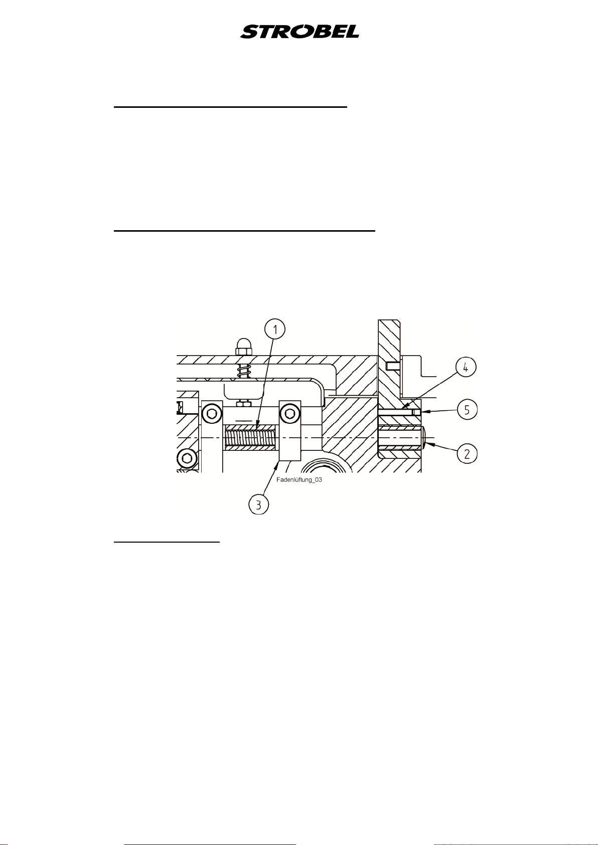
Tread lifting in the needle bar hea d
The lifter bar (4) for the tread lifting in the needle bar head has to be set so that
the thread can be lifted when the looper stands vertically over the needle as the
needle retracts and the loop pick-up is done up to the moment when the looper
has reached the needle centre with the left looper point as the needle
advances. (
The thread breaking at the needle bar is 0.35 - 0.4 N.
Fig. 4)
Spring tension at t he plate bearing arm
The tension of the spring (1) needs to be adjusted to the material to be
processed; for shoes it can be up to 200 N for example. The spring tension can
be set using the setting screw (2). (
Fig. 12)
Fig. 12
4.9.1
Plate arm lifting
The plate arm lifting is about 12 - 14 mm and can be adjusted using the lever
(3). (
Fig. 12)
22 MA_441-1-2_A1_180830_en
4.10
4.10.1
Needle setting
The setting dimension for the needle bar can be found in the table in point "
Abridged version of adjustment manual".
2.5
Height adjustment of t he ne e dle (Fig. 13)
Using this special construction, the height of the needle can be adjusted. This
device proves to be quite useful when using different needle thicknesses. The
height of the needle can be adjusted by turning the eccentric (6), which features
a groove, that is located on the front side of the needle bar head. Make sure
that the needle of any thickness passes over the feed cup with a gap of about
0.1 mm in the area between the point and the eye of the needle. After
loosening the screw (5) of the needle setting plate (4) and then adjusting the
height of the needle, the screw (5) has to be tightened again.
Fig. 13
23 MA_441-1-2_A1_180830_en

4.11
Replacing the looper
After loosening the clamping screw (1) (
(2), the looper can be removed.
When inserting a new looper, make sure that it contacts the needle or feed cup
neither when it is in the front nor when it is in the rear position(see also
installation dimension (L), point "2.5 Abridged version of adjustment manual").
The wide looper back should be set up as parallel as possible to the needle.
Fig. 14) at the head of the looper shaft
Fig. 14
24 MA_441-1-2_A1_180830_en
4.12
4.12.1
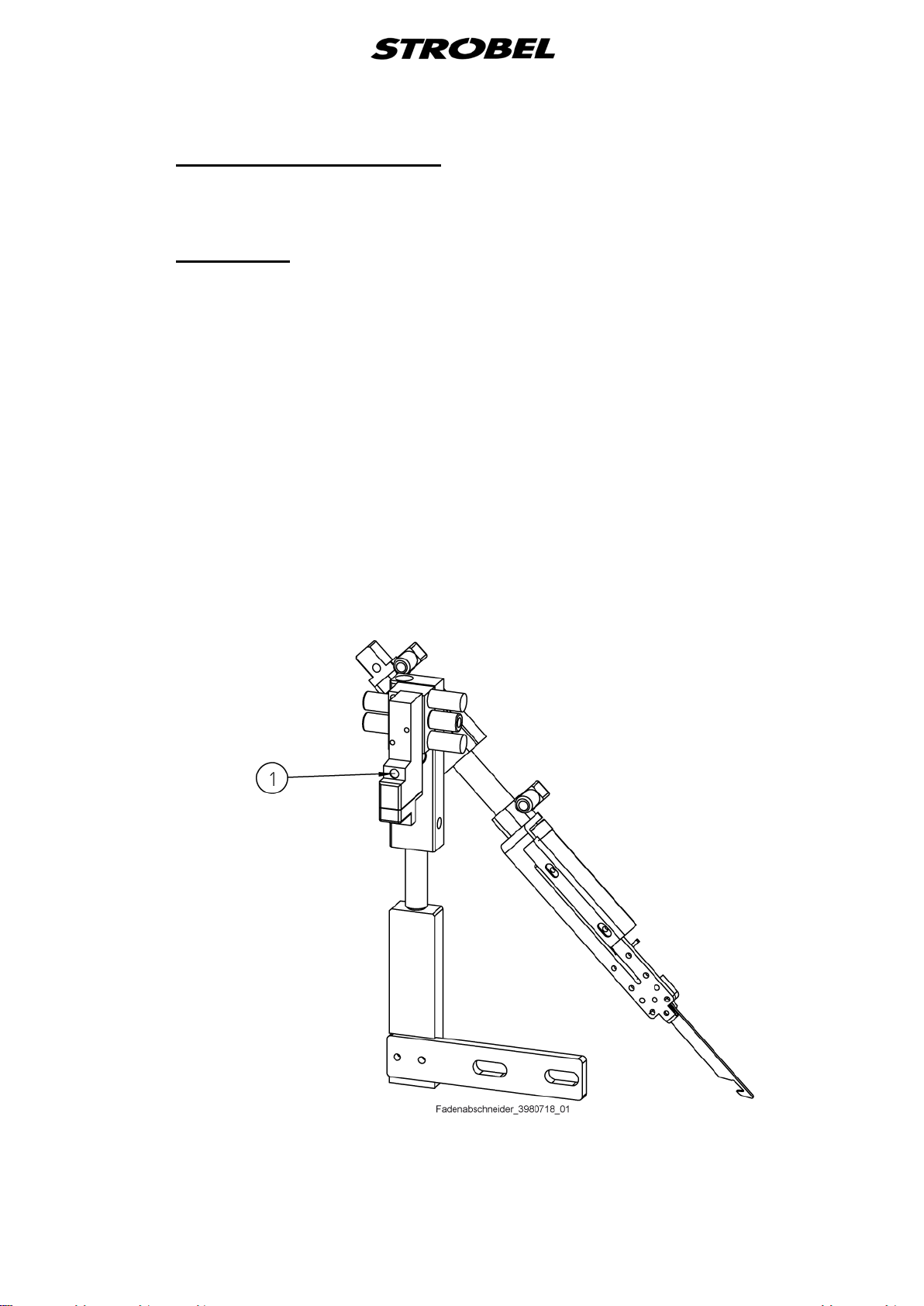
Thread trimmer (optional)
The optional thread trimmer is controlled by an electro-pneumatic control when
the right pedal is pressed back.
Calibration
Before mounting the thread trimmer, the 2 threaded pins (10) (
stand need to be removed. Then the thread trimmer is mounted on the stand
with the 2 supplied screws. It is aligned so that the thread puller, when it is
extended, DOES NOT collide with the feed cup, looper and needle and picks
up the thread between needle and looper.
CAUTION: The needle position needs to be adjusted for the thread trimmer
before the thread trimmer is put into operation.
More Details see point „4.14.3 Adjustment of the needle position
for the use of our thread trimmer“.
The thread trimmer can be checked by triggering the button (1) on the backside
of the valve, which is mounted on the thread trimmer, using a pointed object
(e.g. ballpoint pen).
(Fig. 15)
Fig. 24) in the
Fig. 15
25 MA_441-1-2_A1_180830_en

4.13
Positions
With the control AB611 or AB425
Function
Setting the reference position
This function sets the reference position.
Function
Setting positions 1 and 2
This function sets the two positions.
The control has two positions. The positions are set exclusively by
programming the control.
A position is determined by a position input and output value. The values
correspond to the number of increments (steps), counted from an entered
reference position. A rotation is divided into 360 steps (increments) thereby, i.e.
1 step = 1 degree.
Parameter
F-170
Parameter
F-171
CAUTION!
In order to ensure a safe or proper sequence there should be at least 50
steps (increments) between two positions.
Furthermore there should be 25 steps between position input value and
output value of the same position (very important for internal functions of
the control).
For the precise programming of the individual positions refer to point "4.14
Setting the positions".
The setting of the positions can be easily checked using the F-172 function.
Refer to point "4.15 Display of the needle positions"
26 MA_441-1-2_A1_180830_en
Machine with or without gathering device:
The machine requires two needle positions and, depending on sewing drive,
possibly also a reference position.
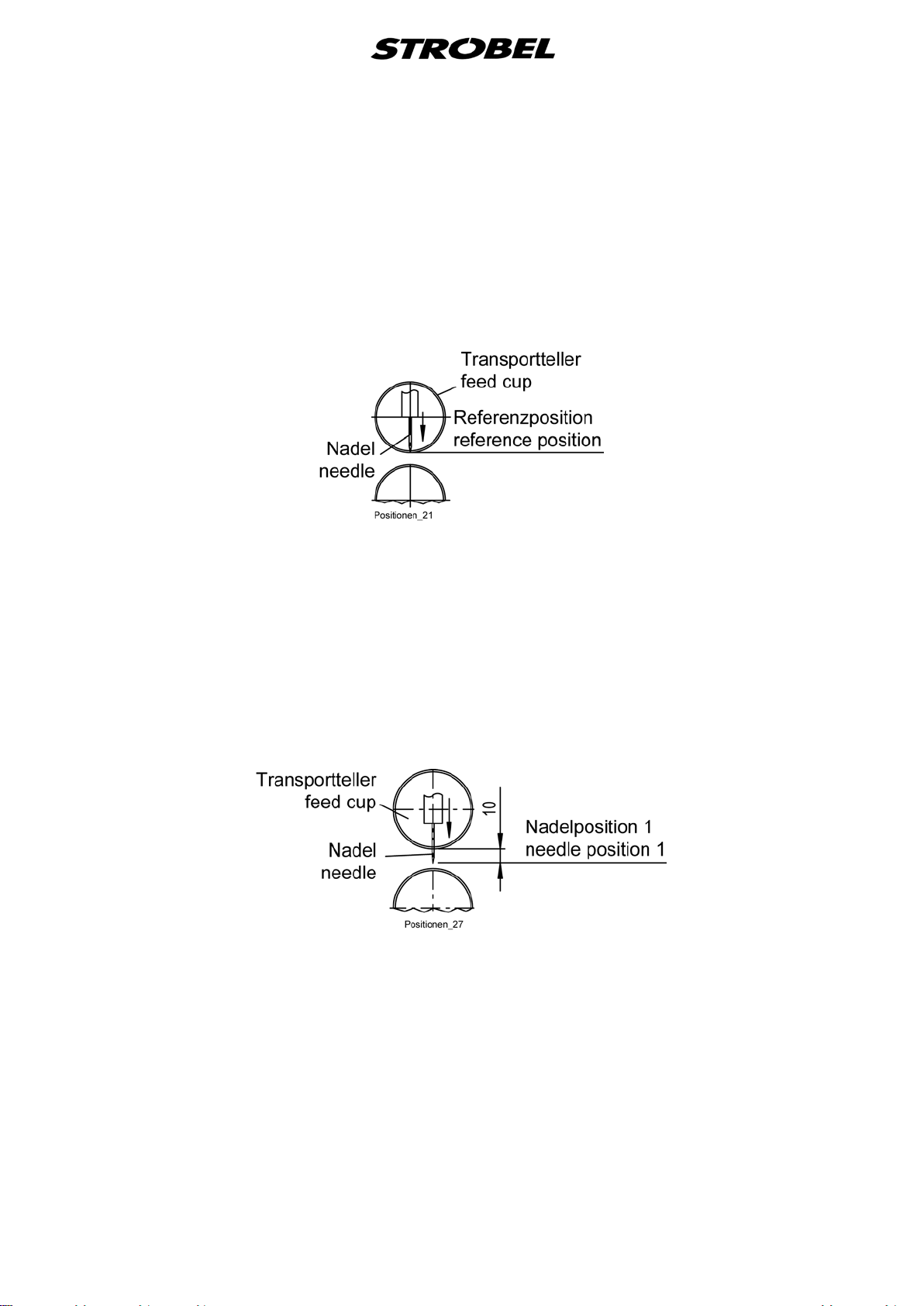
Reference position (Fig. 16):
The reference position needs to be set so that the point of the needle
concludes with the outer plate edge in the direction of the piercing.
Fig. 16
Refer to the enclosed sewing drive instructions for the programming of the
positions on the motor.
Needle position (when stop inside the stitch with pedal position “0” (Fig. 17)):
The needle position needs to be set so that the distance between the
outer plate edge in the direction of the piercing and the point of the needle
is about 10 mm.
The needle position is position 1 at the sewing drive.
Fig. 17
27 MA_441-1-2_A1_180830_en

Needle position (when stop outside the stitch with pedal position “-2” (Fig. 18)):
The needle position needs to be set so that the distance between the
point of the needle in the direction of the piercing and outer plate edge is
about 4 mm.
The needle position is position 2 at the sewing drive.
Fig. 18
Afterwards, check its function by manually actuating the thread trimmer.
4.14
4.14.1
Setting the positions
Refer also to point "
4.13 Positions"
Setting the reference position
After entering the code number "1907" and the button "E" for the technician
level:
- Select parameter F-170. Display shows:.1.7.0.
- Press the "E" button. Sr 1_
- Press the ">>" button. P0 I_I
Turn the handwheel in the machine's direction of rotation
until the rotating icon in the display disappears and then set
the handwheel or needle to the reference position of the
sewing machine (Fig. 16).
- Press the "E" button. .1.7.1.
- Exit the programming level by pressing the button "P"
or
continue with point: "4.14.2 Setting the position 1 and 2" with step 2.
28 MA_441-1-2_A1_180830_en

Needle positions
Parameter
Value
F-451
P1E
036
F-452
P1A
061
F-453
P2E
342
F-454
P2A
009
Starting point for the stepper motor
Parameter
Value
F-749
220
4.14.2
Setting the position 1 and 2
After entering the code number "5913" and the button "E" for the technician
level:
- Select parameter F-171. Display shows:.1.7.1.
- Press the "E" button. Sr2_
- Press the ">>" button. P1E
Keep turning the handwheel in the machine's direction of
rotation until the display of "P1E" changes into the display of
the position value and then set the handwheel or needle to
the position 1 of the sewing machine (Fig. 17). Remember or
record the position value.
- Press the "E" button. P2E
Keep turning the handwheel in the machine's direction of
rotation until the display of "P2E" changes into the display of
the position value and then set the handwheel or needle to
the position 2 of the sewing machine (Fig. 18). Remember or
record the position value.
- Press the "E" button. P1A
Keep turning the handwheel in the machine's direction of
rotation until the display of "P1A" changes into the display of
the position value and then turn the handwheel until the
position value "P1E + 25" is displayed.
- Press the "E" button. Display shows: P2A
Keep turning the handwheel in the machine's direction of
rotation until the display of "P2A" changes into the display of
the position value and then turn the handwheel until the
position value "P2E + 25" is displayed.
- Press the "P" button. .1.7.1.
- Press the "P" button.
At least one cycle needs to be sewn so that the setting is saved before the
machine is switched off.
29 MA_441-1-2_A1_180830_en

Needle positions
Parameter
Value
F-451
P1E
036
F-452
P1A
061
F-453
P2E
273
F-454
P2A
298
Starting point for the stepper motor F-749
Operation without thread cutter
Value 220 (Factory setting)
Operation with thread trimmer
Value 289
4.14.3
Adjustment of the needle position for the use of our thread trimmer
When the thread trimmer is mounted, the needle position parameters and
parameter F-749 must be changed.
After entering the code number "3112" for the supplier level:
- Select parameter F-451 and confirm with the "E" key
- Set the value according to table (Needle positions) and confirm with the
key "E"
- Go to the next parameter and set the value as described in the chart
(Needle positions) and continue this procedure up to Parameter F-454.
- Save the data by pressing the "P" key twice and exit the supplier level.
Starting point for the stepper motor F-749
- Select parameter F-749 and confirm with the "E" key
- Change the value to the value "289" and confirm with the "E" key
- Press the "P" key
Procedure to save the change
- Select parameter F-401
- change value to "1"
- Save the data by pressing the "P" key twice and exit the supplier level.
- Switch the control box off and on again so that the change is saved.
30 MA_441-1-2_A1_180830_en

4.15
Display of the needle positions
Refer also to point "
Function Parameter
Display of the Positions 1 and 2
(down / up)
The setting of the positions can be easily checked using this function.
After entering the code number "1907" and the button "E" for the technician
level:
- Select parameter F-172. Display shows: .1.7.2.
- Press the "E" button. Sr 3
Turn the handwheel according to the motor's direction of rotation.
- Display at the control:
Segment 5 is switched on. ⇒ Position 1E
4.13 Positions"
F-172
4.16
Segment 5 is switched off. ⇒ Position 1A
Segment 6 is switched on. ⇒ Position 2E
Segment 6 is switched off. ⇒ Position 2A
- Press the "P" button. .1.7.2.
- Press the "P" button.
Sewing drive
Refer also to point "
The motor has its own operating instructions included which has information on
programming and circuit diagrams.
4.13 Positions"
31 MA_441-1-2_A1_180830_en

4.17
Working w ith the control AB425
CAUTION!
Switch off the machine electrically!
4.17.1 Setting the stitch length
Function with V850 operating control Parameter
Stitch length setting F-711
In order for the machine to run synchronously, the stitch length needs to be
determined first. To do so, you take a Texon strip for example and feed the strip
between both plates, with the machine switched off, by turning the handwheel
until the needle has pierced 11 times. Afterwards you measure the distance of
the 11 piercings and enters this via the parameter "F-711".
Fig. 19
32 MA_441-1-2_A1_180830_en

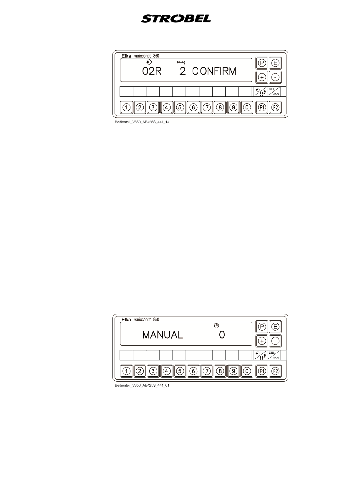
4.17.2
Working w ith operating contr ol (V850) (Fig. 2 0 )
Activation of control panels by code.
For activation you need a two part code, available from your Strobel agent.
Procedure of activation:
- Press and hold button “P” and switch on the machine by “S1”
- Open the supplier level by code “3112” and confirm with “E”
- Select parameter “F-798” and confirm with “E”, for code-A
- Enter the 5-digit code-A and confirm with “E”
- Select parameter “F-799” and confirm with “E”, for code-B
- Enter the 5-digit code-B
- Save data by pressing “P” two times
Fig. 20
Example:
Example:
33 MA_441-1-2_A1_180830_en

1. Display "Standard"
1 Program number
2 Sector
3 Reduction differential transport
- Additional display of the current sector by arrow symbols
- The letter behind the program number (L/R) indicates whether it is a
left or right shoe.
- If no program is saved at the current program number, then this will be
indicated by "No Prog".
34 MA_441-1-2_A1_180830_en
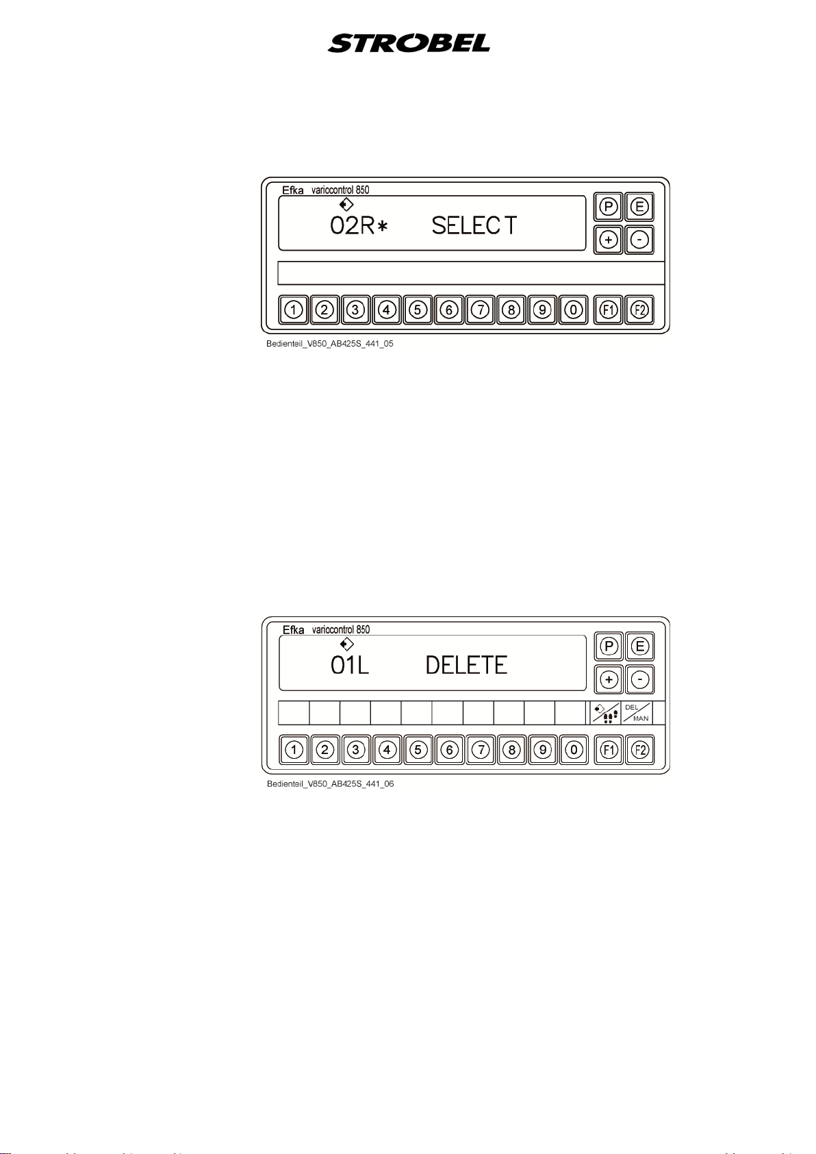
2. Display "Program selection"
- Press the "F1" button in the "Standard" display.
- Enter the program number using the keypad or "+/–" buttons.
- Confirm the entry with the "E" button.
- Corresponding program is loaded.
- Return to the standard display
- If no corresponding program is saved, this is indicated by the "*" icon.
- Use the "P" button to switch into the "Standard" display without
selecting a program.
3. Display "Delete program"
- Press the "F2" button in the "Standard" display.
- Enter the program number using the keypad or "+/–" buttons.
- Confirm the entry with the "E" button.
- If no corresponding program is saved, this is indicated by the "*" icon.
- Otherwise a confirmation is expected once more to delete the
program definitely.
35 MA_441-1-2_A1_180830_en

- Confirm the deletion process with the "E" button.
- The two programs that belong together are always deleted (e.g.
00R+01L, 02R+03L…)
- Return to the standard display ("No Prog")
- Use the "P" button to switch into the "Standard" display without
deleting a program.
4. Display "Programming mode"
● Add new program
- Press the "P" button in the "Standard" display invoke the programming
mode.
- Enter the program number using the keypad or "+/–" buttons.
- Confirm with the "E" button or exit with the "P" button.
36 MA_441-1-2_A1_180830_en
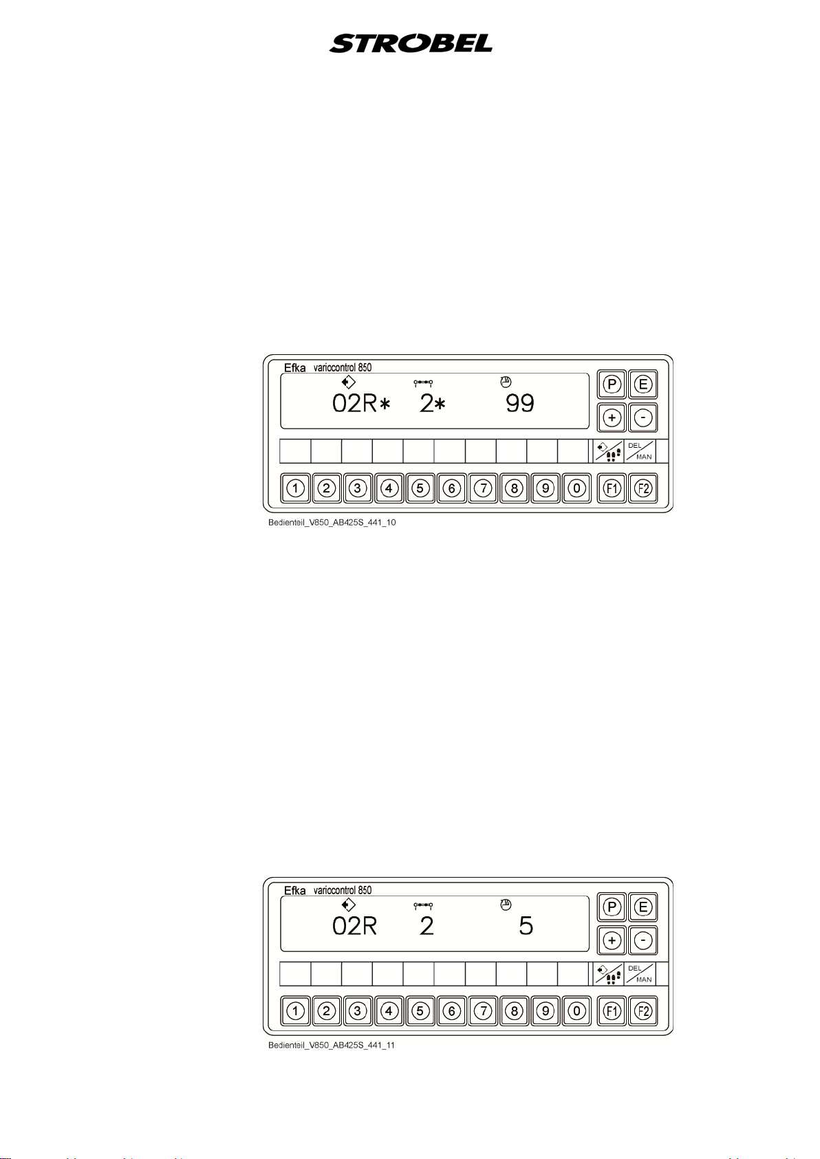
- It starts with the value of the differential transport of sector 1.
- The value "99" indicates that no differential transport has been set for
the current sector.
- Reduction differential transport begins to flash.
- The "*" icon behind the values of the program and sector numbers
indicate that this program number or this sector has not yet been
occupied (if the "*" icon cannot be seen in this display, then this
program number or the sector is already occupied).
- The corresponding value for differential transport can be set using the
"+/–" buttons.
- The sector is increased with the "E" button or the knee switch and the
next value for the differential transport can be entered.
- Once the desired sectors are programmed, the program is saved by
pressing the "P" button.
- During saving, the second associated program is created
automatically (e.g. 00R+01L, 02R+03L, 04R+05L…)
- Return to the standard display
● Process existing program
Add sector to the end
- Activate programming mode.
- Select and confirm program number.
- Press the "F1" button to display last sector.
37 MA_441-1-2_A1_180830_en

- Add a new sector with the "E" button or knee switch.
- Set the differential transport and save with "P" button.
- During saving, the second associated program is adapted
automatically (e.g. 00R+01L, 02R+03L, 04R+05L…)
- Return to the display "Standard".
Delete last sector
- Activate programming mode.
- Select and confirm program number.
- Press the "F1" button to display last sector.
- Press the "F2" button to delete the last sector ("Delete" is displayed).
- Press the "E" button to confirm the entry.
- The "P" button cancels the deletion process.
- If cancelling, return to display "Programming mode".
38 MA_441-1-2_A1_180830_en
- To make sure, the deletion needs to be confirmed by pressing the "E"
button again.
- Save and return to the display "Standard" by pressing the "P" button.
- The deletion process is also transferred to the second associated
program (e.g. 00R+01L, 02R+03L, 04R+05L…)
Process sector
- Activate programming mode.
- Select and confirm program number.
- If the program number is invalid, "No Prog" is displayed.
- Page through to the corresponding sector with the "E" button or knee
switch.
- Set the value of the differential transport.
- Save with the "P" button
- The processing process is automatically transferred to the second
associated program (e.g. 00R+01L, 02R+03L, 04R+05L…)
- Return to the display "Standard".
5. Display "Manual mode"
- The switching of the display into manual mode is done by a
parameter.
39 MA_441-1-2_A1_180830_en

4.17.3
Parameter und Functions F-714 (Class 441-2)
Parameter 714 defines the 1st sector for the start of sewing. Two options are
available.
The mirroring is done automatically in the right order for the right or left shoe.
The examples are based on an insole with 8 sectors.
The starting point for sewing is always at sector 1
Fig. 21
Parameter 714 = 0
40 MA_441-1-2_A1_180830_en

Parameter 714 = 1
41 MA_441-1-2_A1_180830_en

F-715 = 0
In this mode, e.g. the sewing program 02 for a right shoe
F-715 = 1
In this mode, e.g. the sewing program 02 for a right shoe
4.17.4 Parameter and Functions F-715 ( Clas s 441-2)
Function Parameter
Selection of processing via parameter F-715 F-715
With the Parameter F-715 you can decide if you want to use a sewing program
for pairwise shoe processing or single shoe processing.
and the sewing program 03 for a left shoe is repeated in
continuous sequence.
is repeated until you manually switch to the next sewing
program 03 for a left shoe.
4.17.5 Parameter and Func t ions F-760 (Class 441-2)
Function Parameter
Setting synchronized differential feed F-760
With this parameter, the synchronisation of the differential transport can be
finely adjusted if the material pairings have different friction values.
The factory setting is set to value "6".
In the factory setting "6" our off-sewing material is transported synchronously
between feed- and front cup.
If the materials have different values of friction, we have the option of fine
adjustment of the differential feed to ensure always synchronized operation.
Value 0 – 5 = More transport by the front cup
Value 6 = factory setting
Value 7 – 10 = Less transport by the front cup
After entering the code number "3112" for the supplier level:
- Select parameter F-760
- Press the "E" key
- Enter the value or correct the value up or down
- Press the "P" key
42 MA_441-1-2_A1_180830_en

Procedure to save the change
- Select parameter F-401
- change value to "1"
- Save the data by pressing the "P" key twice and exit the supplier level.
- Switch the control box off and on again so that the change is saved.
4.17.6
Copy sewing programs to a not he r machines (Class 441-2)
Here is a description, how to copy the sewing programs from a control box to a
USB stick and then transfer them to another control box.
Procedure with control panel V850
1.
Copy the sewing program from the controller
- Insert the USB stick into the control box
- Press the "P" key and switch the control box on at the same time
- Enter code 3112 and confirm with key "E"
- Select parameter F-514 and confirm with "E"
- Press the "F2" key
- Press the "E" key twice
- Then the file with the sewing programs is copied to the USB stick
- Press the "P" key and switch off the controller
- Now you can remove the USB stick from the control box
The file name, which is copied to the USB stick, is titled by the controller
"0300DATA.pay". This file can be renamed up to 8 characters, but the
extension always must be ".pay".
Example:
0300DATA.pay =>> shoe-1.pay
2.
Copy the sewing program to a control box
- Insert the USB stick into the control box
- Press the "P" key and switch the control box on at the same time
- Enter code 3112 and confirm with key "E"
- Select parameter F-515 and confirm with "E"
- Press the "F2" key
- Select the sewing program (for example, shoe -1.pay) using the
+/- buttons on the control panel
- Press the "E" key twice
- File with the sewing program is up-loaded in the control box
- Press the "P" key and switch off the controller
- Now you can remove the USB stick from the control box
43 MA_441-1-2_A1_180830_en

4.17.7 Brief instruction (Class 441-2)
44 MA_441-1-2_A1_180830_en

4.18
4.19
Servicing the mac hine
The individual oiling points of the machine are supplied fully automatically; the
machine needs no maintenance in this regard.
An oil change should be done about twice a year, depending on the amount of
dust and hours of operation. It is recommended to use 0.5 litres of oil for that;
an oil with the viscosity of 46 cSt.
(Recommended oil: Shell Voltol 46)
Also clean the plastic lever and the boreholes.
General notes
Further details such a sewing instructions and the like can be found in the
operating instructions, on the homepage.
45 MA_441-1-2_A1_180830_en

5
5.1
5.2
Notes on repair and adjustments
Feed cup assembly
In addition to the transport and front cups attached to the normal version,
optional transport and front cups are offered according to the various materials
to be processed and requirements with suitable gearing and edge heights; they
can be freely combined with each other.
Replacing the feed cup
If the feed cup in the machine should be exchanged with other geared feed
cups, then proceed first as follows:
1. Remove material guide (1) - 2x screw (2). (Fig. 22)
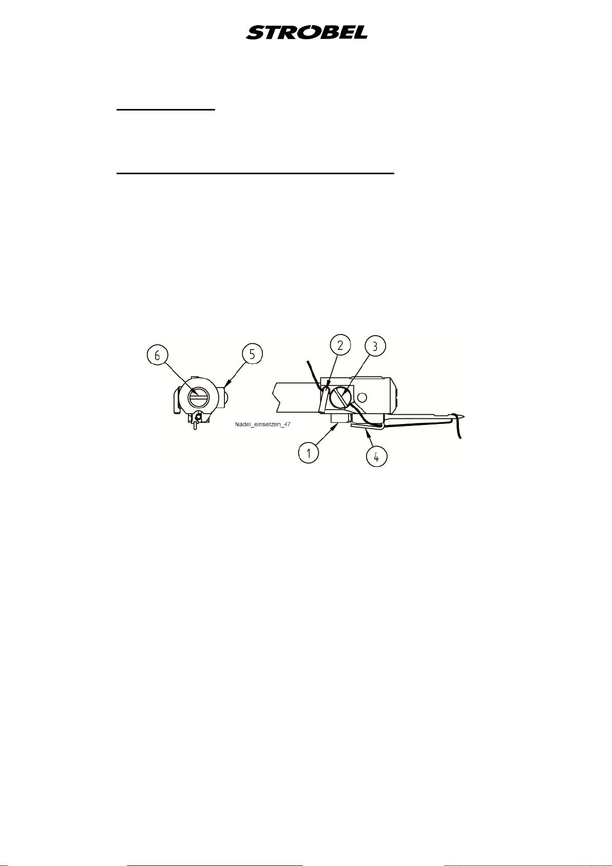
2. Pull out needle (1), cylinder head screw (2), needle clamping plate (3),
pressure spring (4) and needle setting plate (5). (Fig. 23)
3. Screw out the flat-head screws (6) of the feed cup attachment; take feed
cup off upwards. (Fig. 14)
4. The assembly of the exchanged feed cup is done in reverse order.
Fig. 22
46 MA_441-1-2_A1_180830_en

Fig. 23
5.2.1.1
Chain tension
The chain for the feed cup drive can be tensioned from above by loosening the
threaded pin (3) (
Fig. 22) the chain tensioner (5) (Fig. 4).
47 MA_441-1-2_A1_180830_en

5.3
Setting and installation instr uc t ion for the Strobel gather ing device
(See also operating instructions point "4.1.1.1 Processing with gathering
device")
The gathering device EV (1) (Fig. 24) is attached to the machine housing with
two screws (9). There are two threads made in the housing for that.
When mounting the EV, make sure that after swivelling down the guide (2)
between the feed cups it comes to a stop about 1 mm under the plate edge and
about 5 – 6 mm to the right of the needle.
For a subsequent mounting of the EV, a ∅24 borehole needs to be made in the
tabletop for the rods (3) (see tabletop drawing in the operating instructions).
Fig. 24
48 MA_441-1-2_A1_180830_en

258.10.27
Elekrischer Schaltplan AB425S Kl. 441-2 ab Ausf. 1
Electrical wiring diagram AB425S Cl. 441-2 as of version 1
Schrittmotor (SM)
Step motor (SM)
(B)
ge - ye
(A)
SM
(A)
rt - rd
rt/ws - rd/wh
sw - bk
sw/ws - bk/wh
ge/ws - ye/wh
gn/ws - gn/wh
gn - gn
(B)
B5
1
2
3
4
5
6
Schrittmotor (SM)
Step motor (SM)
Nähantriebsteuerung
Sewing drive control
195.0063

258.10.28
Elekrischer Schaltplan AB425S Kl. 441-2 ab Ausf. 1
Electrical wiring diagram AB425S Cl. 441-2 as of version 1
0V
+5V
Analog1
X10
1
5
7
br - bn
ws - wh
0V
Knietaster
X11
knee switch
2
3
br - bn
ws - wh
+24V
Impuls FA
1
X12
impulse FA
2
EV
br - bn
ws - wh
ws - wh
1V1
br - bn
br - bn
br - bn
ST2
2
+5V
ws - wh
gn - gn gn - gn
3
4
0V
br - bn
11
br - bn
18
+24V
ws - wh
26
27
+24V
Analog1
Knietaster
knee switch
Impuls FA
impulse FA
Nähantriebsteuerung
Sewing drive control
1V1 Magnetventil "Lüftung" (LÜ) solenoid valve "lifting" (LÜ)
EV Einhaltevorrichtung gathering device
ST2 Stecker Steuerkasten (Nähantrieb) plug control box (sewing drive)
X10 9-poliger Stecker "Sollwertgeber" 9-pin plug "setpoint device"
X11 RJ12 Buchse "Knietaster" RJ12 bush "knee switch"
X12 2-poliger Stecker "Fadenabschneider" 2-pin plug "thread trimmer"
ws - wh
29
gathering device (EV)
Einhaltevorrichtung (EV)
195.0064

258.30.28
Montageplan AB425S Kl. 441-2 ab Ausf. 1
Assembly plan AB425S cl. 441-2 as of version 1
298.0069
Knietaster
knee switch
Sollwertgeber
298.0688
setpoint device
298.0718
thread trimmer
Fadenabschneider
gathering device
Einhaltevorrichtung
296.0830
step motor
Schrittmotor
398.0717
(head)
(Oberteil)
296.0817
M
B6
Steuerung Nähantrieb
control box sewing drive
B41
DC15..
M
B5
stepper motor 2
EB...
B80
M
B776
stepper motor 1
V8 ..
ST21
Adapter 1113229
LSM+ HSM ; LSM +IPG
ST20
M
B2
DC15..
ST2
B18
IPG...
HSM...
LSM...
Efka
(998.0560)
Bedienteil
+ -
P E
F2
F1
M
298.0663
operating control
variocontrol 850
Efka
298.0560
Sollwertgeber
Motor Nähantrieb
motor sewing drive
setpoint device
Efka
296.0562
1 2 3 4 5 6 7 8 9 0
195.0065

259.00.67
Pneumatischer Schaltplan Kl. 441-2 ab Ausf. 1
Pneumatic circuit diagram cl. 441-2 as of version 1
1 A 1
1 V 1
B
B
P R
A
A
10bar max
0 Z 1 Wartungseinheit service unit
1 V 1 4/2-Magnetventil "Einhaltevorrichtung" (P-EV) 4/2-solenoid-way valve "gathering device" (P-EV)
1 A 1 Zylinder "Einhaltevorrichtung" (P-EV) cylinder "gathering device" (P-EV)
FA Fadenabschneider thread trimmer
0 Z 1
6bar
FA
195.0553

259.10.67
Pneumatischer Bauschaltplan Kl. 441-2 ab Ausf. 1
Pneumatic construction circuit diagram cl. 441-2 as of version
Einhaltevorrichtung / Gathering device (EV)
178.0009 2 Spanplattenschraube Ø5x30 chipboard screw Ø5x30
193.0896 1 Tragschiene mounting rail
293.0469 1 Schalldämpfer R 1/8 silencer R 1/8
293.0772 2 Verschlußschraube R 1/8 lock screw R 1/8
293.0837 2 L-Einschraubanschluss R 1/8-4 L-threaded connection R 1/8-4
293.0850 1 L-Einschraubanschluss R 1/8-6 L-threaded connection R 1/8-6
293.0853 2 L-Einschraubanschluss M5-4 L-threaded connection M5-4
293.0975 1 Wartungseinheit service unit
297.0170 1 Schnellverschlusskupplung Ø8 coupling Ø8
298.0362 1 Miniatur-Zylinder miniature cylinder
298.0510 1 4/2-Wege Magnetventil 4/2-solenoid-way valve
298.0511 1 Eingangsmodul G1/8 links input module G1/8 left
298.0512 1 Eingangsmodul G1/8 rechts input modul G1/8 right
gathering device
Einhaltevorrichtung
293.0853
298.0362
196.0716 Ø4
196.0716 Ø4
293.0837
298.0512
Magnetventil
solenoid valve
298.0510
293.0469
298.0511
193.0772
293.0850
193.0473 Ø6
Fadenabschneider / Thread trimmer (FA)
293.0849 1 T-Einschraubanschluß R1/8x6 T-threaded connection
293.0975 1 Wartungseinheit service unit
297.0170 1 Schnellverschlusskupplung Ø8 coupling Ø8
298.0718 1 Fadenabschneider thread trimmer
298.0718
thread trimmer
Fadenabschneider
193.0478 Ø8
195.0554
293.0849
(293.0850)
service unit
Wartungseinheit
293.0975
(293.0841)
193.0478Ø8 3000 lg
297.0170
service unit
Wartungseinheit
293.0975
(293.0841)
193.0478Ø8 3000 lg
297.0170

56
Softstart ON/OFF
1
Not assigned
1
Thread trimmer ON/O FF
1
Output M3 ON/OFF
1
Button ">>" Seg6
0
Button "-" Seg7
Automatic lifting in the seam
0
1
Button "-" Seg8
Automatic lifting at the seam end
0
1
Strobel-Switchable Functions - DC1200-AB611A
Explanation:
0 = Off
1 = On
Machine class
F-290 Mode
Button "E" Seg1
Button "E" Seg2
Button "+" Seg3
Button "+" Seg4
Button ">>" Seg5
"Control"
Stand: 23.07.2018 - PT_AB611A _441-1_180723
Basic position "needle position 1"
Basic position "needle position 2"
00
0
0
0
0
0
1
1
Setting range
Preset at mode 56
56 56 56
0 0 0
0 0 0
0 0 0
0 0 0
0 1 1
1 0 0
0 0 0
1 1 1
441-1
441-1F

1
10
56
0
2
Thread trimmer
OFF/ON
0
1
OFF/ON
1
Lifting with
pedal position "-1"
0
4
EB401
4
000
254
390
Maximum speed n2-
(setting range)
n2_
9900
0070
1500
setting range
n2-
Softstart
OFF/ON
0
1
machine standstill
50
0
1
000
359
990
0
1
Strobel-Parameter list - DC1200-AB611A
Machine class
F-467 Motor selection
F-290 Mode
F-365 Machine classes selction
F-013
F-014
F-019
F-026
F-100 Stitch number softstart
F-110 Positioning speed n1
F-111
Characteristic of the pedal
Output 3
00
0
0
070
Setting range
Unit
min-1 200 200 200
min-1 2200 1800 1800
Preset at mode 56
3 3 3
56 5 5
0 0 0
0 0 1
0 1 1
3 3 3
4 4 4
002 002 002
441-1
441-1F
F-115 Softstart speed n6
F-121
F-134
F-153
F-161 Direction of rotation of the motor
F-180 Number of turn-back s t eps
F-181 Switch delay for turn back
F-182 Turn backOFF/ON
Lower limit of the n-max
Holding force during
0200
00
000
min-1 0500 0500 0500
min-1 0200 0200 0200
0 0 0
05 05 05
0 0 0
Grad 040 175 175
ms 200 010 010
0 0 0

Strobel-Parameter list - DC1200-AB611A
Braking effec t when changing
transmission ratio 1:1)
Braking effec t when changing
transmission ratio 1:1)
00
55
Accelerating power of the drive
transmission ratio 1:1)
0
1
47
0
6
0150
9999
Thread trimmer (M1)
5000
On-time
Thread trimmer (M1)
0000
5000
Output M3
5000
On-time
Output M3
0000
5000
0000
5000
Machine class
F-207
F-208
F-219 Positioning force when stopping the dr ive
F-220
F-234 Restarting after activated run inhibition
F-240 Selecting the input function I n. 1
F-270 Selection o9f the position sensors
F-272 Transmission motor shaft to machine shaf t
the set-point <= 4 steps
(indicated valus only with
the set-point >= 5 steps
(indicated valus only with
(indicated valus only with
00
55
00
55
00
55
00
Setting range
Unit
Preset at mode 56
15 15 15
20 20 20
04 04 04
20 20 20
1 0 1
00 00 00
0 6 6
1000 1000 1000
441-1
441-1F
F-280
F-281
F-284
F-285
F-288 Delay time till lifting On
Stand: 23.07.2018 - PT_AB611A _441-1_180723
Delay time
Delay time
0000
0000
ms 0100 0000 0000
ms 0180 0100 0100
ms 0000 0200 0200
ms 0300 0100 0100
ms 0200 0380 0380

56
Softstart ON/OFF
1
Not assigned
1
Thread trimmer ON/O FF
1
Output M3 ON/OFF
1
Button ">>" Seg6
0
Button "-" Seg7
Automatic lifting in the seam
0
1
Button "-" Seg8
Automatic lifting at the seam end
0
1
Strobel-Switchable Functions - DC1500-AB425S
Machine class
Explanation:
0 = Off
1 = On
F-290 Mode
Button "E" Seg1
Button "E" Seg2
Button "+" Seg3
Button "+" Seg4
Button ">>" Seg5
"Control"
Stand: 24.07.2018 - PT_AB425S _441-2_180724
Basic position "needle position 1"
Basic position "needle position 2"
00
0
0
0
0
0
1
1
Setting range
Preset at mode 56
56 56 56
0 0 0
0 0 0
0 0 0
0 0 0
0 1 1
1 0 0
0 0 0
1 1 1
441-2
441-2F

1
10
56
2
OFF/ON
1
Output 3
OFF/ON
0
1
Lifting with
pedal position "-1"
0
4
Characteristic of the pedal
EB401
0
4
000
254
070
390
Maximum speed n2-
(setting range)
n2_
9900
1500
Lower limit of the n-max
setting range
0200
n2-
Softstart
OFF/ON
0
1
Holding force during
machine standstill
00
50
0
1
359
000
990
0
1
Strobel-Parameter list - DC1500-AB425S
Machine class
F-467 Motor selection
F-290 Mode
F-365 Machine classes selction
F-013
F-014
F-019
F-026
F-100 Stitch number softstar t
F-110 Positioning speed n1
F-111
Thread trimmer
00
0
0
Setting range
Unit
min-1 200 200 200
min-1 2200 1800 1800
Preset at mode 56
3 1 1
56 5 5
0 1 1
0 0 1
0 1 1
3 3 3
4 4 4
002 002 002
441-2
441-2F
F-115 Softstart speed n6
F-121
F-134
F-153
F-161 Direction of rotation of t he m otor
F-180 Number of turn- back steps
F-181 Switch delay for turn back
F-182 Turn backOFF/ON
0070
000
min-1 0500 0500 0500
min-1 0200 0200 0200
0 0 0
05 05 05
0 0 0
Grad 040 040 040
ms 200 200 200
0 0 0

Strobel-Parameter list - DC1500-AB425S
Braking effec t when changing
transmission ratio 1:1)
Braking effec t when changing
transmission ratio 1:1)
00
55
Accelerating power of the drive
transmission ratio 1:1)
0
1
47
0
6
0150
9999
Thread trimmer (M1)
5000
On-time
Thread trimmer (M1)
0000
5000
Output M3
5000
On-time
Output M3
0000
5000
0000
5000
Machine class
F-207
F-208
F-219 Positioning force when stopping the drive
F-220
F-234 Restarting after activated run inhibition
F-240 Selecting the input function In.1
F-270 Selection o9f the position sensors
F-272 Transmission motor shaf t t o machine shaft
the set-point <= 4 steps
(indicated valus only with
the set-point >= 5 steps
(indicated valus only with
(indicated valus only with
00
55
00
55
00
55
00
Setting range
Unit
Preset at mode 56
15 15 15
20 20 20
04 04 04
20 35 35
1 0 1
00 00 00
0 0 0
1000 1000 1000
441-2
441-2F
F-280
F-281
F-284
F-285
F-288 Delay time till lift ing On
Stand: 24.07.2018 - PT_AB425S _441-2_180724
Delay time
Delay time
0000
0000
ms 0100 0000 1000
ms 0180 0180 0180
ms 0000 0200 0200
ms 0300 0300 0300
ms 0200 0200 0200


Und wir können noch mehr für Sie tun!
Unser Lieferprogramm bietet für jede Branche und
jegliche Anforderung genau die richtige Problemlösung.
And we can do a lot more for you!
Our range offers the correct problem solution for
every branch and for all requirements.
Für die Bekleidungsindustrie:
Ein- und ZweifadenHochleistungs-Saummaschinen
DoppelblindstichSaummaschinen
Zweifaden-BlindstichStafermaschinen
Roll- und Flachpikiermaschinen
Pikier-Automat
und
weitere Spezial-Nähmaschinen
For the clothing
industry:
Single and two thread high
performance hemming
machines
Bluff edge hemming machines
Two thread blind stitch felling
machines
Roll and at padding machines
Automatic lapel padding
machine
Für die Schuhverarbeitung:
Einfaden-Überwendlichmaschinen mit und ohne
Differentialtransport
For the shoe industry:
Single-thread overseaming machines with and without differential feed
Für Kürschnereien
und Pelzkonfektion:
Pelzschnellnäher
For the fur industry:
High-speed fur sewing machines
Für Heimtextilien:
Ein- und ZweifadenBlindstichmaschinen
For the home textiles
industry:
Single and two thread
blind stitch machines
Für die Polsterverarbeitung:
Ein- und ZweifadenÜberwendlichmaschinen
Ein- und ZweifadenBlindstichmaschinen
For the upholstery
industry:
Single and two thread
overseaming machines
Single and two thread
blind stitch machines
Für die Konfektion
technischer Textilien:
Ein- und ZweifadenÜberwendlichmaschinen
For the processing
of technical textiles:
Single and two thread
overseaming machines
and other special sewing
machines

Noch Fragen?
Dann rufen Sie uns an, schreiben Sie uns oder
kommen Sie einfach bei uns vorbei.
Sie können jederzeit weitere Informationen über
unsere Produkte anfodern oder die StrobelNähmaschinen in unserem Ausstellungsraum live
erleben. Wir freuen uns auf Sie!
Any further questions?
Then phone, write or simply come and see us. You
can have further information about our products at
any time, or experience the Strobel machines live in
our show room. We’re looking forward to meeting you!
Sp ez i al ma s ch in e n Gm bH
Postfach 1242
82168 Puchheim
Siemensstraße 3
82178 Puchheim
DEUTSCHLAND
www.strobel.biz
Telefon: +49 89 80096-0
Telefax: +49 89 80096-190
 Loading...