


For the professional user
Mechanic‘s Instructions
Für den professionellen Anwender
Mechanikeranleitung
Class:
Klasse:
Model:
Ausführung:
Dated:
Stand:
560-11, -21
4
Spezialmaschinen GmbH

The sign of quality
ou nd the Strobel trademark on every Strobel
Y
machine leaving our works. And with good reason.
This symbol is a guarantee of the high quality of
our products. Quality which creates trust – trust
in our technology, our service and, not least of all,
in our good name.
Im Zeichen der Qualität
ie nden die Strobel-Schutzmarke auf jeder
S
Strobel-Maschine, die unser Werk verlässt.
Und das aus gutem Grund. Denn dieses Zeichen
garantiert Ihnen die hohe Qualität unserer
Produkte. Qualität, die Vertrauen schafft – in unsere
Technik, unseren Service und nicht zuletzt in unseren
guten Namen.

A decision with future
trobel clients know that they can expect a particularly
S
high standard of performance from our company and our
machines. Now you have settled for one of our products.
For us this is a source of encouragement and of obligation
to Justify your trust.
If you wish to prot from the performance and efciency of
your Strobel machine as long as possible, exact handling
and thorough care is necessary. For this reason we kindly
request that you read the operating instructions closely.
It provides all the information you need for trouble free
operation.
And if you do happen to need a spare part the enclosed
spare parts list gives a complete overview. It is clearly
classied according to components so that you can nd the
required part quickly and easily. In order to avoid errors we
request you to quote machine class, machine number and
part number completely on your spare part order.
We wish you lots of success in your work with your new
Strobel machine.
Spezialmaschinen GmbH


Mechanic’s instructions
STROBEL series 560
Contents
1 General notes on safety ............................................................................................ 5
2 General ..................................................................................................................... 7
2.1 Operating instructions ..................................................................................... 7
2.2 Class identification, serial number and orientation of the machine ................. 7
2.3 Range of application and intended use .......................................................... 7
2.4 Technical Data ................................................................................................ 8
2.5 Summary of setting instructions ..................................................................... 8
3 Instructions for repair and settings ............................................................................ 9
3.1 Mounting the needle plate .............................................................................. 9
3.1.1 Removing the needle plate (Fig. 1) .................................................... 9
3.1.2 Remounting the needle plate ............................................................. 9
3.1.3 Setting the needle plate (Fig. 1 and Fig. 2) ...................................... 10
3.1.4 Setting the needle (Fig. 1) ................................................................ 11
3.1.5 Changing the needle glide plate (Fig. 1) .......................................... 11
3.1.6 Thread holder ................................................................................... 11
3.1.7 Setting the thread holder (Fig. 1) ..................................................... 11
3.2 Setting the needle lever ................................................................................ 12
3.2.1 Lateral setting of needle lever (Fig. 3 and Fig. 4) ............................. 12
3.2.2 Setting of the needle lever in relation to the thread take-up (Fig. 5) 13
3.2.3 Setting the stitch width (Fig. 6) ......................................................... 14
3.3 Loop stroke ................................................................................................... 14
3.3.1 Setting the loop stroke (Fig. 5) ......................................................... 14
3.4 Looper .......................................................................................................... 15
3.4.1 Removing and remounting the looper (Fig. 7) .................................. 15
3.4.2 Setting the looper ............................................................................. 15
3.4.3 Tension of V-belt for looper drive (Fig.9) .......................................... 15
3.5 Thread take-up ............................................................................................. 16
3.5.1 Thread take-up movement (Fig. 8) ................................................... 16
3.5.2 Upper thread tension (Fig. 9) ........................................................... 17
3.5.3 Lower thread tension (Fig. 9) ........................................................... 17
3.5.4 Setting the thread wiper (Fig. 10) ..................................................... 18
1 MA_560_A4_180619_en

3.6 Plunger ......................................................................................................... 19
3.6.1 Removing and remounting the plunger (Fig. 11 and Fig. 12) ........... 19
3.6.2 Mounting and setting the plunger drive
(Fig. 11, Fig. 13, Fig. 14 and Fig. 15) ............................................... 21
3.6.3 Mounting and setting of the plunger drive
(Fig. 12, Fig. 16, Fig. 17 and Fig. 18) ............................................... 24
3.6.4 Setting the digital stitch depth display (Fig. 14 and Fig. 19) ............. 27
3.7 Plunger plate ................................................................................................ 28
3.7.1 Setting the plunger plate (Fig. 11 and F ig. 17) ................................. 28
3.8 Distance looper point to knife point (Fig. 20) ................................................ 28
2 MA_560_A4_180619_en

Appendix
Circuit diagrams
Connecting the sewing ma chine:
258.21.72 Electrical connection diagram cl. 560-11 from version 4
258.21.73 Electrical connection diagram cl. 560-21 from version 4
259.00.57 Pneumatic circuit diagram cl. 560 from version 4
259.10.57 Pnaumatic construction circuit diagram cl. 560 from version 4
Connecting digital display:
258.21.24 Electric connection diagram Kl. 170, 560, ZM
Subject to change without prior notice
3 MA_560_A4_180619_en

4 MA_560_A4_180619_en

1
General notes on safety
Every person in charge of setting up, operating, servicing and repairing the
machine must first read and understand the operating instructions and
particularly the safety instructions before starting up the machine.
Failure to comply with the following safety instructions can lead to bodily
injury or damage to the machine.
1. The machine must only be operated by persons familiar with the relevant
operating instructions and who have been instructed accordingly.
2. Before commissioning also read the notes on safety and the operating
instructions of the sewing drive manufacturer.
3. Only use the machine in the intended manner and never without the
provided guards. Always observe the pertinent safety regulations.
4. Switch off the main switch or pull the power plug for threading, changing
the reels, exchanging sewing tools such as needle, gripper, needle plate,
transport devices, possibly cutter and cutting block, for cleaning and when
leaving the workplace as well as for maintenance.
5. General maintenance tasks may be carried out only by properly trained
persons in accordance with the operating instructions.
6. Repair work, retrofitting and maintenance may be carried out only by
technicians or specially trained personnel.
7. When servicing or repairing pneumatic equipment, the machine must be
disconnected from the pneumatic supply. Exceptions are only allowed for
adjustment work and tests of functionality performed by specially trained
technicians.
8. Only specially qualified technicians may work on the electrical equipment.
9. It is forbidden to work on electrically live components! Exemptions are
covered by the EN50110 (DIN VDE0105) regulations.
10. Any retrofitting or alterations to the machine may only be performed under
strict compliance with all pertinent safety regulations.
11. Only use our approved spare parts when servicing and/or repairing the
machine.
12. It is forbidden to operate the sewing head until it is determined that the
entire sewing unit complies with EU provisions.
13. It is essential that you observe and follow these instructions as well as the
generally valid safety regulations.
5 MA_560_A4_180619_en

14. Warning instructions given in the operating instructions that pertain to
especially dangerous parts of the machine must be indicated at these
positions using a safety symbol.
Warning instructions given in the operating instructions that pertain to
special injury hazards for operating personnel or technicians must be
indicated at these positions using a safety symbol.
6 MA_560_A4_180619_en

2
2.1
2.2
2.3
General
Operating instructions
Any person involved in the installation, operation, maintenance and repair of
the machine must have read and understood the operating instructions and
mainly the safety instructions before starting the machine.
Class identification, serial number and ori e nt a t ion of the machine
The operating side of the machine is the basis for descriptions referring to
sides. The class identification (type) as well as serial and model number (after
the dash) are located on the right hand side of the housing.
Range of applicati on a nd intended use
Class 560-11, -21
Automatic single thread blind stitch spot tacking machine for attaching woven
labels, as well as for attaching linings, hems, trouser turn-ups and seams.
All machines are equipped with fully automatic control of the sewing process,
preselection of 1 to 20 (max. 255) spot tacking stitches, thread trimmer and
pneumatic lifting.
7 MA_560_A4_180619_en

2.4
Technical Data
Recommended rated speed 1600 min-1
Motor power 400 W
Number of tack stitches 6, 8, 10, 12, 14
Toothed belt pulley/machine Z = 38
Toothed belt profile HDT 5M-9
Kind of stitch Single thread blindstitch spot tacking
Stitch type 101
Needle system GROZ-BECKERT 1717 VRUE
Needle size 90
Thread polyester continuous filament
Thread size 120/2
Air pressure 6 bar
Average air consumption
Cl. 560-11 290 l/h
Cl. 560-21 380 l/h
2.5
Required space (m) 0.6 x 1.06
Noise:
medium noise level at a speed of
n = 1200 min-1 LpAm 72 dB (A)
Noise test according to DIN 45635-48-1 KL3
Summary of setting instruct ions
Theoretic needle radius 43.6 mm
Needle glide plate 43.59 -0.04 mm
Needle plate radius 43.67 +0.03 mm
Stitch width 0.7 – 2.0 mm
factory setting 1.2 mm
Loop stroke (left hand needle penetration) 2.5 mm
Needle stroke, Needle eye to looper point 1 ±0.2 mm
(left hand needle penetration)
Distance between looper point and needle 0.1 mm
Plunger lifts needle in its highest position 0.1 - 0.2 mm
Distance between looper and knife:
in basic position 2 mm
in trimming position 1 - 1.5 mm
8 MA_560_A4_180619_en

3
3.1
3.1.1
Instructions for repair and set t ings
ATTENTION, danger!
Observe safety and operating instructions before realizing
any maintenance and repair works.
Failure to do so may result in heavy bodily injuries.
Mounting the needle plate
ATTENTION!
Switch off machine electrically!
Removing the needle pla t e (Fig. 1)
3.1.2
1. Switch off machine electrically, plunger is lifted
2. Remove the needle
3. Remove set collar (1)
4. Loosen screws (2)
5. Remove needle plate carefully
Remounting the needle plate
Remount needle plate in reserved sequence, but make sure that after mounting
the set collar the movable knife moves over the counterknife easily and does
not jam.
9 MA_560_A4_180619_en

Fig. 1
3.1.3
Setting the needle plate (Fig. 1 and Fig. 2)
The theoretic needle radius of 43.6 mm should be by 0.01 - 0.04 mm smaller at
the needle glide plate; i.e. a checked needle is lifted by
0.01 - 0.04 mm. Control by means of a dial gauge.
If this setting is correct, there should be a distance of 0.03 - 0.06 mm between
needle and needle plate radius.
By loosening threaded pins (3) on the left and right hand side of the head and
by loosening fastening screws (2) the needle plate can be pushed carefully
upwards or downwards towards the needle.
Attention! Make sure that the needle plate is in horizontal position when
tightening the screws.
Fig. 2
10 MA_560_A4_180619_en

3.1.4
3.1.5
3.1.6
3.1.7
Setting the needle ( Fig. 1)
In lateral direction a needle No. 90 is set in a way that at the left hand needle
penetration there is a distance of 0.15 - 0.2 mm between the left hand needle
side and the needle plate groove. For resetting, loosen screw (4) and displace
part (5).
Changing the needle glide plate (Fig. 1 )
The needle glide plate is mounted to the lower side of the needle plate. Loosen
screws (6) to remove the needle glide plate.
Thread holder
The thread holder is mounted between needle plate an knife and prevents the
spot tack to come off. It holds the trimmed while the other thread end is pulled
out of the material by means of the thread wiper.
Setting the threa d holder (Fig. 1)
The air gap between spring and thread holder should be 0.03 mm for the
recommended thread (continuous polyester 120/2), so that the thread is hold
but not jammed.
Remove the Thread holder, take out the spring from the front groove and bend
it slightly to the front to enlarge the air gap or bend it backwards to reduce the
air gap.
11 MA_560_A4_180619_en

3.2
3.2.1
Setting the needle lever
ATTENTION!
Switch off machine electrically!
Lateral setting of needle lever (Fig. 3 and Fig. 4)
Control cam (1) is set in a way that the needle lever being in its lowest position
(lower dead point) the radius corresponding to the needle penetration (right
hand needle penetration small radius, left hand needle penetration large
radius), stands exactly under roll (2). Only at the largest stitch width the roll
touches the cam at the right hand needle penetration.
Attention: cam (1) is bored to gearwheel (3) (Fig. 5).
Fig. 3
Fig. 4
12 MA_560_A4_180619_en

3.2.2
Setting of the needle lever in relation to the thread take-up (Fig. 5)
By turning eccentric disc (1) on shaft (2) the movement of the needle lever is
set in a way that needle lever and thread take up move downwards
simultaneously.
Then drill first borehole in sense of rotation, screw in threaded pin and check
loop stroke (see point “3.3 Loop stroke“).
Fig. 5
13 MA_560_A4_180619_en

3.2.3
Setting the stitch width (Fig. 6)
Stitch width is the distance between left and right hand needle penetration
(needle oscillation).
Standard stitch width setting is 1.2 mm. By moving the adjusting ring (1) on the
bolt (2) stitch width is adjusted.
Move to left → stitch width is small
Move to the right → stitch width is greater
Fig. 6
3.3
3.3.1
Loop stroke
Loop stroke is the needle course from its lowest position to the point where the
looper point stands above the needle centre.
Setting the loop stroke (Fig. 5)
ATTENTION!
Switch off machine electrically!
In the factory a loop stroke of 2.5 mm at the left hand needle penetration is set,
i.e. the distance from the looper point to the end of the thread eye is
1 ±0.2 mm.
If materials or threads are sure where - due to their structure – the loop is too
small or too large, reset the loop stroke as follows:
1. Loosen both screws in gearwheel (4)
2. Turn endless screw (5) at the back side of the head to the right or to the
left until the required loop stroke is obtained
3. Retighten both screws and make sure that the shaft has no axial play
4. Turn machine manually and check the new settings
14 MA_560_A4_180619_en
3.4
3.4.1
Looper
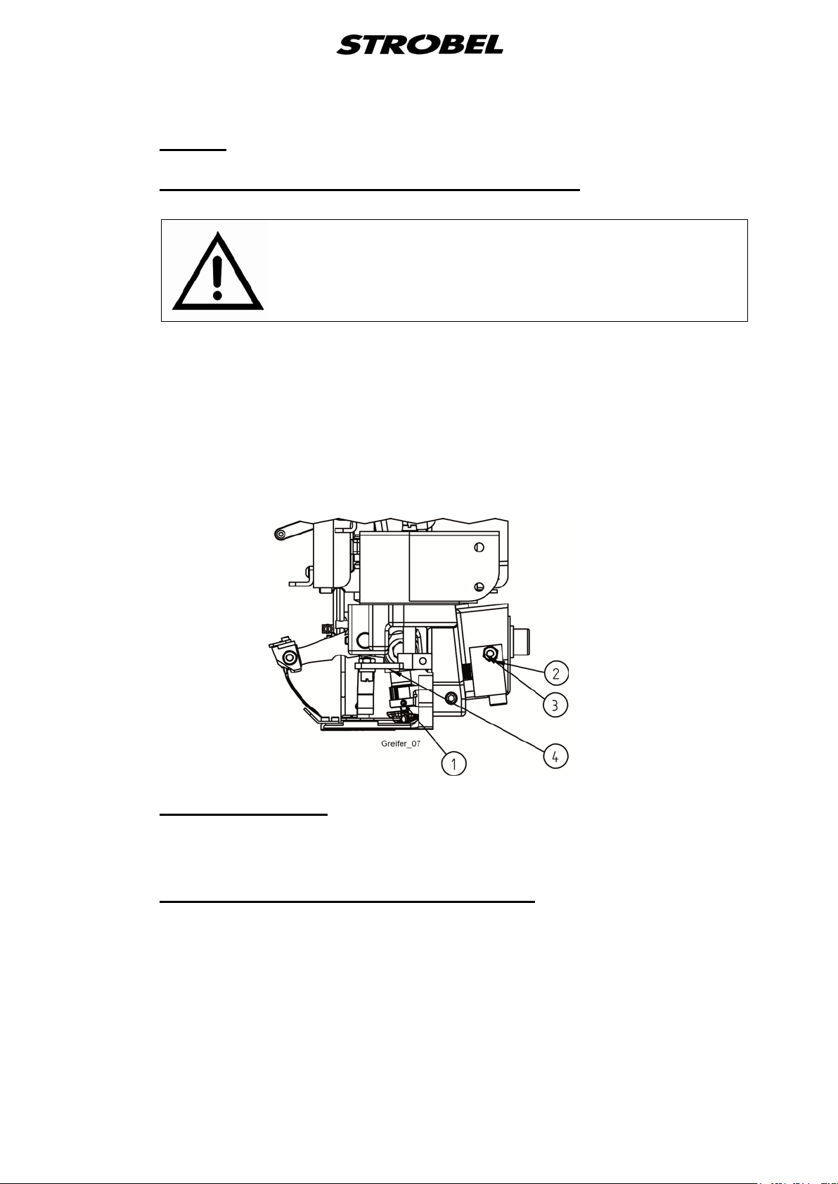
Removing and remounting the looper (Fig. 7)
ATTENTION!
Switch off machine electrically!
Remove the needle plate, loosen threaded pin (1) in the looper shaft and
remove the looper downwards.
When remounting the looper make sure that the threaded pin presses against
the surface of the looper’s shaft nose which fixes the looper in correct position.
Nevertheless it is recommended to recheck the loop stroke.
Fig. 7
3.4.2
3.4.3
15 MA_560_A4_180619_en
Setting the looper
When setting the looper height there should be a distance of 0.1 mm between
looper point and needle.
Tension of V-belt for looper drive (Fig.9)
By loosening nut (2) and screwing in of the screw (3) the distance between
looper shaft and V-belt bearing is enlarged and thus the V-belt is tensed.
Then refix the screw by means of the hexagon nut.
3.5
3.5.1
Thread take-up
During the upwards movement the thread take-up pulls the thread and tightens
the loop coming off the looper back. At the same time it feeds a new piece of
thread.
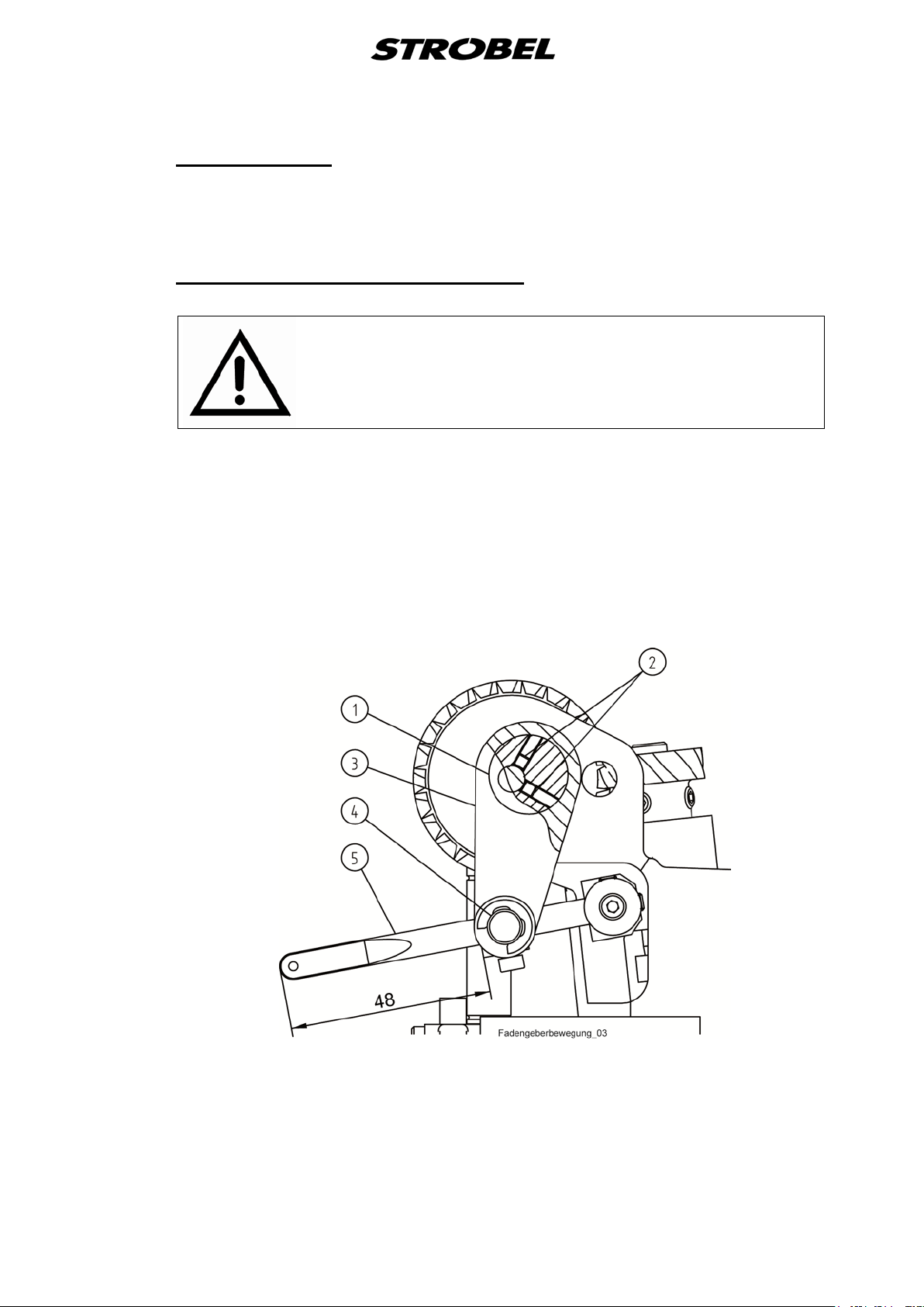
Thread take-up movement (Fig. 8)
ATTENTION!
Switch off machine electrically!
Thread take-up and needle lever should start their downwards movement
simultaneously.
By adjusting the eccentric (1) by loosening the screws (2) ((3) in the connecting
rod) of the date of the take-up lever movement can be adjusted.
By moving the cross bearing (4) on the take-up lever (5) whose rash can be
changed (factory setting 48 mm).
These two measures , the machine can be adapted to the diverse threads .
Fig. 8
16 MA_560_A4_180619_en
3.5.2
3.5.3
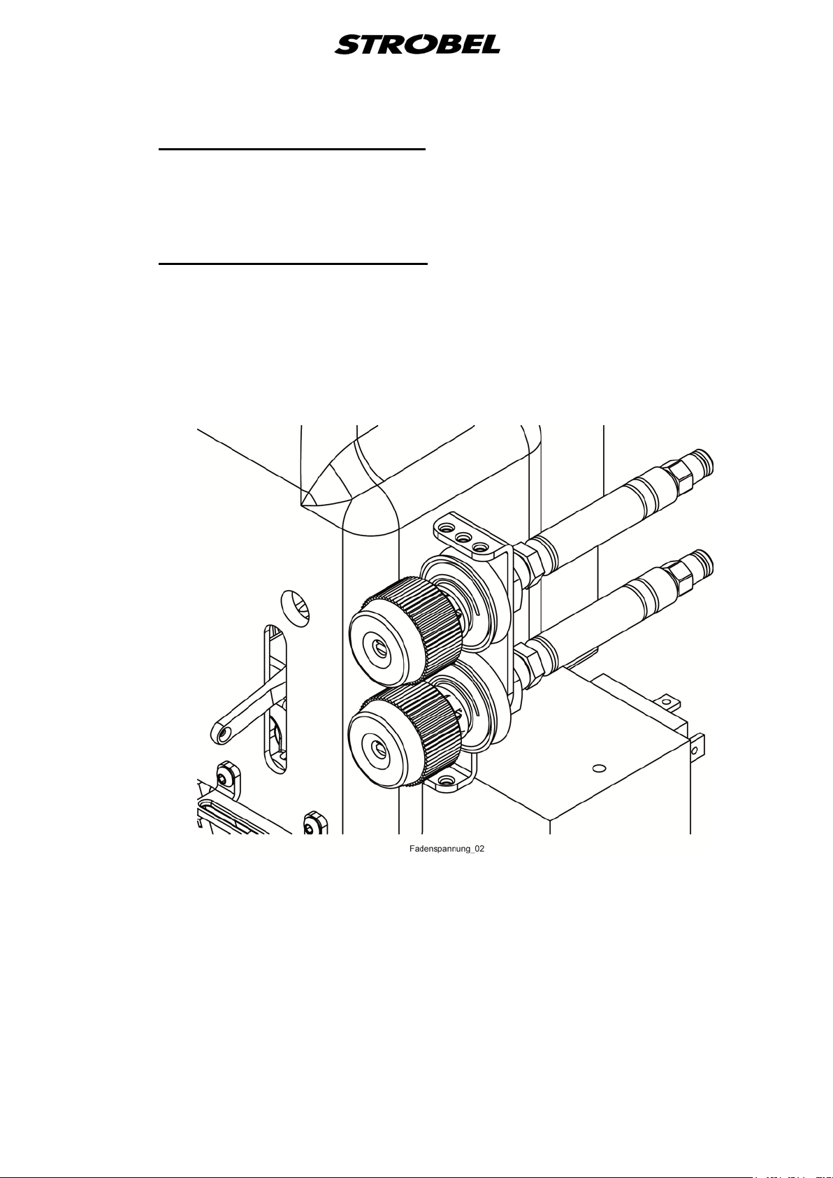
Upper thread tensi on (Fig. 9)
The upper thread tension mainly regulates the seam appearance.
Depending on the material these value have to be modified to obtain an
optimum seam appearance.
Lower thread tension (Fig. 9 )
The lower thread tension regulates the length of the initial thread.
Turning clockwise → shorter thread
Turning counterclockwise → thread gets longer
Depending on the material these value have to be modified to obtain an
optimum seam appearance.
Fig. 9
17 MA_560_A4_180619_en
3.5.4
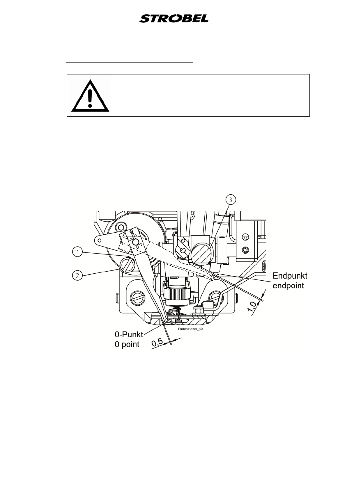
Setting the threa d wiper (Fig. 10)
ATTENTION!
Switch off machine electrically!
In the lower Stop position the distance between needle plate and thread wiper
should be 0.5 mm.
The upper end is by loosening the nut (1) and turn the eccentric bolt (2) set.
Adjust the eccentric bolt so that the left needle entry of the thread puller has 1
mm from the needle lever (3).
Fig. 10
18 MA_560_A4_180619_en

3.6
3.6.1
Plunger
The plunger presses the material upwards into the needle plate opening to
enable the needle to penetrate the material.
At plunger zero-point (plunger value “0” / plunger is at its top-most position) the
needle is lifted 0.1 – 0.2 mm from the plunger.
For the setting refer to:
Cl. 560-11: Point 3.6.2 Mounting and setting the plunger drive
Cl. 560-21: Point 3.6.3 Mounting and setting the plunger drive
Removing and remounting the plunger (Fig. 11 and Fig. 12)
ATTENTION!
Switch off machine electrically!
Lift the machine and loosen threaded pin (1) in plunger sleeve (2) and remove
then the plunger upwards.
Remounting in reserved sequence. Please make sure that when tightening the
threaded pin it presses onto the surface of the plunger shank.
19 MA_560_A4_180619_en
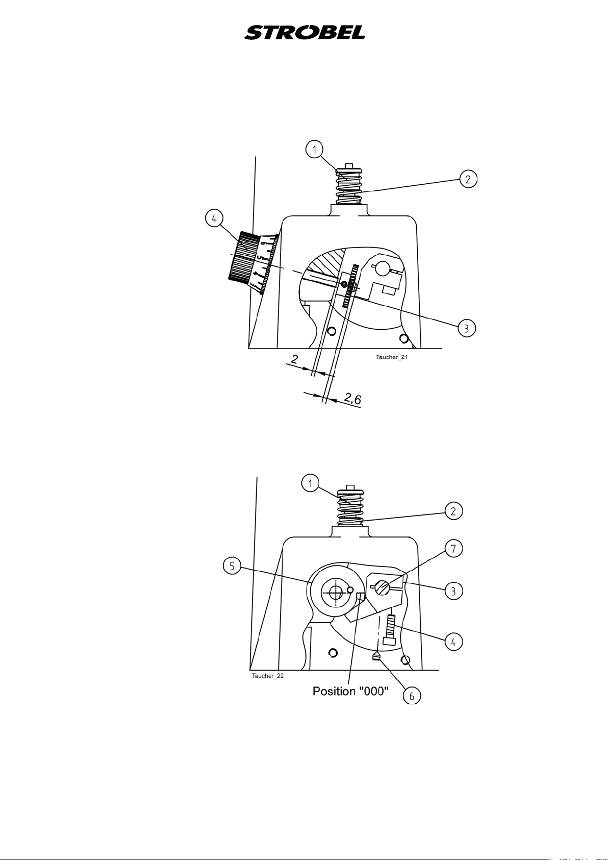
Fig. 11
560-11
Fig. 12
560-21
20 MA_560_A4_180619_en

3.6.2
Mounting and sett ing the plunger drive (Fig. 11, Fig. 13 , Fig. 14 and Fig. 1 5 )
Class 560-11 only
ATTENTION!
Switch off machine electrically!
With repair or replacement, e.g. of the swivel drive, the plunger drive must be
newly mounted and set. Please heed the following instructions:
1. Swivel drive (1) must be aligned in its secured state so that the shaft of
the swivel drive, looking from the back, is turned to the limit in the
clockwise direction.
2. Insert and screw in the connection flange (2) to the limit so that the first
threaded hole is over the groove and fix with the threaded pin with journal
(3) and secure with nut (4). (Fig. 13)
3. Mount shaft (5) and secure to the surface with the 2 threaded pins (6).
Then tighten the last threaded pin (7) and secure the rest of the nuts (4).
(Fig. 13)
4. Setting lever (4) on shaft (5) (Fig. 14):
a. Lightly clamp the lever on the shaft.
b. Turn the regulating bolt (1) in the thread on the lower arm. Push on
gearwheel (2) and regulating knob (3) and secure provisionally; pay
attention to the surface of the regulating bolt (1). (Fig. 14)
c. Set the gearwheel (3) to the dimension 2.6 mm. (Fig. 11)
d. Turn the regulating bolt (1) back using the regulating knob (3) until
gearwheel (2) rests against the cast eye. (Fig. 14)
e. Bring the swivel drive to the limit, press lever (4) to the crest of the
regulating bolt (1), tighten the lever (4) and bore with shaft 130.0460
(5). (Fig. 14)
5. Screwing regulating bolt (1) until by means of lever (4) it has moved the
magnet approx. 0.2 mm back from its limit stop. (Fig. 14)
6. Loosen the gear (2), push it back to the limit Stop on the boss and tighten
it well. (Fig. 14)
7. Screwin the regulating bolt further 2 ¾ turns (distance from gear and boss
approx. 2 mm), press regulating knob (4) to the limit Stop (lower arm) and
tighten it well. The plunger adjustment is limited by the limit stops of gear
and regulating bolt at the lower arm. (Fig. 11)
21 MA_560_A4_180619_en

8. Loosen screw (1) slightly in lever (2) and beat the lever upwards until the
plunger lifts the needle by 0.1 - 0.2 mm; tighten well screw (1). (Fig. 15)
ATTENTION!
Make sure that lever (2) is in axial position. (Fig. 15)
9. Finally fix set collar (3) to lever (2). This set collar serves as axial limit stop
and facilitates further plunger settings. (Fig. 15)
Fig. 13
Fig. 14
22 MA_560_A4_180619_en

Fig. 15
23 MA_560_A4_180619_en

3.6.3
Mounting and sett ing of the plunger dri ve (Fig. 12, Fig. 1 6 , Fig. 17 and Fig. 1 8 )
Class 560-21 only
ATTENTION!
Switch the machine's electric power off and pull the power
plug.
After e.g. changing the pivot drive, the plunger drive must be remounted and
reset. Please observe the following instructions:
1. Swivel drive (1) must be aligned in its secured state so that the shaft of
the swivel drive, looking from the back, is turned to the limit in the
clockwise direction. (Fig. 16)
2. Insert and screw in the connection flange (2) to the limit so that the first
threaded hole is over the groove and fix with the threaded pin with journal
(3) and secure with nut (4). (Fig. 16)
3. Mount shaft (5) and secure to the surface with the 2 threaded pins (6).
Then tighten the last threaded pin (7) and secure the rest of the nuts (4).
(Fig. 16)
4. Setting of the lever (8) on shaft (5) (Fig. 16):
a. Turn the swivel drive in the clockwise direction, as seen from behind,
to the limit
b. Set lever (1) so that between setting ring (2) and bearing bushing (3)
there is a distance in the lower arm of approximately 2.5 – 3.0 mm.
Tighten lever (1) with cylinder head screw (4). (Fig. 17)
c. Turn the swivel drive in the anti-clockwise direction, as seen from
behind, until the plunger lifts the needle 0.1 – 0.2 mm.
d. Turn cam (5) and lever (3) to one another until the nose rests against
the lever. (Fig. 12)
e. Turn cam (5) approx. 2 mm back and tighten lever (3) with cylinder
head screw (4). (Fig. 12)
f. Bore lever (3) with shaft (7), screw in threaded pin (6) and tighten.
(Fig. 12)
4. Screw machine upper part to the tabletop.
5. Plug in power plug and switch machine on by the main switch.
6. Set the plunger value “0” in the first backtack of the stitch program. (Refer
for this to the operating instructions of the respective sewing drive.)
7. Switch the machine off by the main switch and switch it on again. (A
reference run is made and the first backtack is approached with the
plunger value “0”.)
24 MA_560_A4_180619_en

8. Switch the machine off again by the main switch and pull the power plug.
9. Push the plunger up by hand (until stop by cam).
10. Loosen screw (1) slightly in lever (2) beat the lever upwards until the
plunger lifts the needle by 0.1 - 0.2 mm; tighten well screw (1). (Fig. 18)
ATTENTION!
Make sure that lever (2) is in axial position. (Fig. 18)
11. Finally fix set collar (3) to lever (2). This set collar serves as axial limit stop
and facilitates further plunger settings. (Fig. 18)
Fig. 16
Fig. 17
25 MA_560_A4_180619_en

Fig. 18
26 MA_560_A4_180619_en

3.6.4
Setting the digit a l stitch depth dis play (Fig. 14 and Fig. 19)
Class 560-11 only
ATTENTION!
Switch off machine electrically!
The digital stitch depth display is available as optional extra and can also be
mounted to machines already in use.
The LCD display is attached to the cover (2) with the mounting parts (2).
(Fig. 19)
Fig. 19
Mount the additional parts at the stitch depth knob as shown in Fig. 14 and set
as follows:
Turn the regulating knob (3) backwards until gear (2) touches the boss of the
lower arm. Then screw the second gear (6) to the shaft of the potentiometer
that the digital display shows a value between 003 and 006 and the distance of
the two gears is approx. 1.35 ±0.2 mm.
Electrical connections please see the connecting diagram.
27 MA_560_A4_180619_en
3.7
3.7.1
3.8
Plunger plate
The lifting closed being the spring-loaded plunger plate presses the material to
the needle plate around the area of needle penetration.
Setting the plunger plate (Fig. 11 and Fig. 17)
ATTENTION!
Switch off machine electrically!
The plunger being in its basic position set collar (2) should be fixed approx.
2 - 3 mm. ABOVE THE LOWER ARM: When thicker fabrics are sewn the set
collar is released.
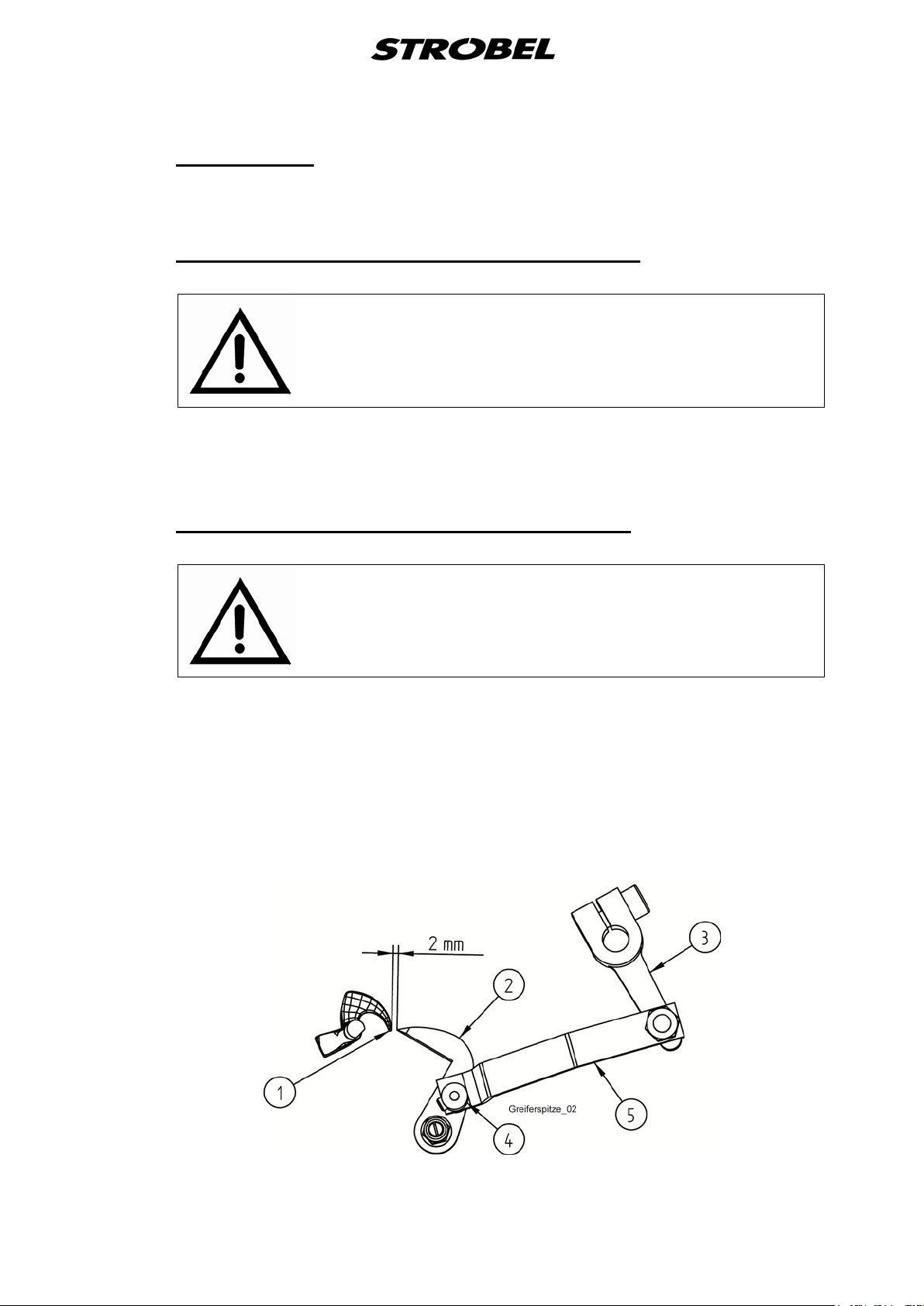
Distance looper point to knife point (Fi g. 20)
ATTENTION!
Switch off machine electrically!
In stillstand position the distance between looper point (1) and knife (2) should
be 2 mm. Regulation by means of lever (3) on the magnet shaft.
Set collar (4) prefig.nts part (5) from moving upwards. Mount set collar (4) in a
way that (5) and knife (2) can do the cutting movement without jamming (play
0.2 mm).
Check this setting when changing the knife.
Fig. 20
28 MA_560_A4_180619_en
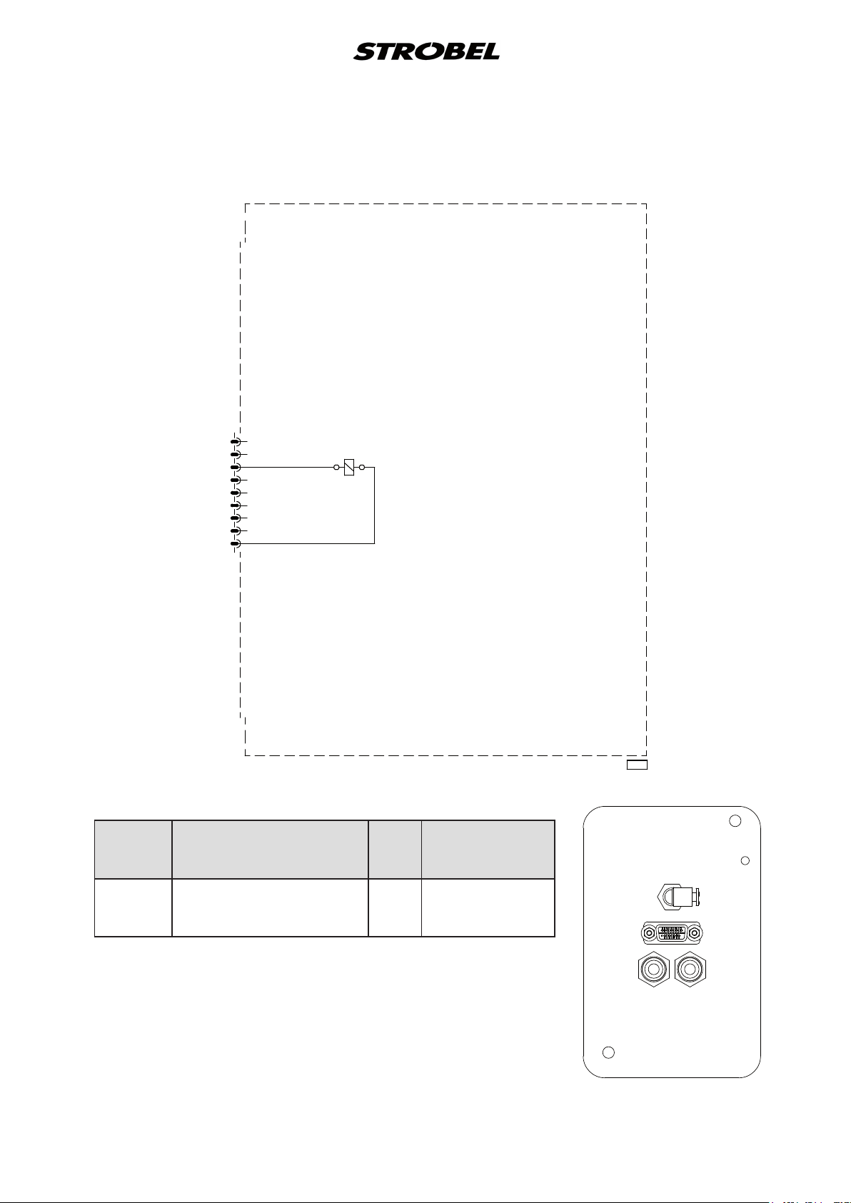
258.21.72en
(1) Nominal voltage 24V =, no-load voltage max. 30V =
Desccription
manual
PIN
Color code
solenoid
Electrical connection diagram Cl. 560-11 as of version 4
Head - Sewing machine
STM2
1
2
bu
3
4
5
6
7
8
bn
9
bn
bu
thread trimmer (FA)
Plug
STM2
Electro-
Strobel-instruction
Sub-D
Thread trimmer (FA) 3
connecting line
9
blue
brown
head - sewing machine
195.0038
Machine cover
4
STM2
A B
Front side
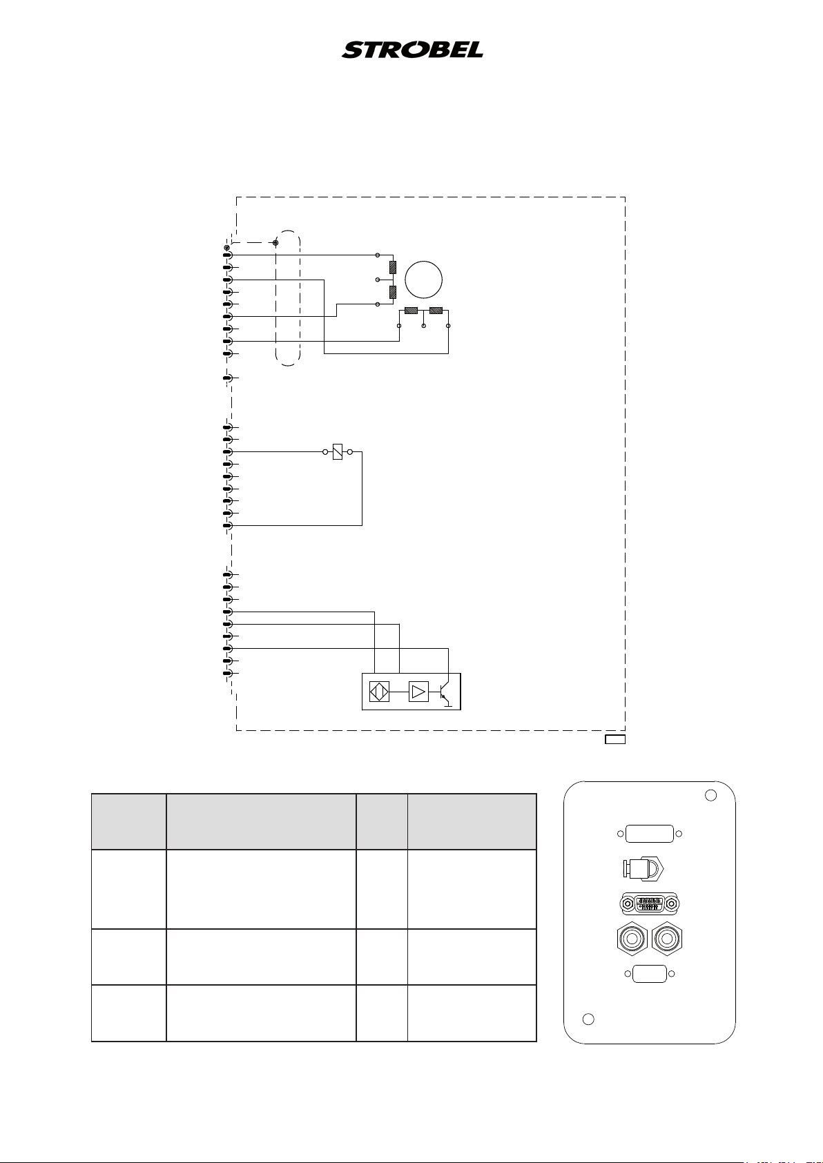
258.21.73en
(1) Nominal voltage 24V =, no-load voltage max. 30V =
Desccription
manual
PIN
Color code
STM5
Spool 2R (B/red)
1
green
STM2
solenoid
3
blue
Electrical connection diagram Cl. 560-21 from version 4
Head - Sewing machine
STM5
STM2
STM1
1
gn
2
wh
3
4
5
ye
6
7
bn
8
9
15
1
2
bu
3
4
5
6
7
8
bn
9
1
2
3
rd
4
wh
5
6
bk
7
8
9
bu bn
B
rd
wh
SM
ye
A
B"
bn
bk
thread trimmer (FA)
0V+5V
OUT
step motor (SM)
A"
og
head - sewing machine
Plug
Strobel-instruction
motor
Step
Spool 1R (A"/orange)
Spool 2L (B"/yellow)
Spool 1L (A/brown)
Thread trimmer (FA)
Electro-
STM1
Hall
sensor
Supply voltage +5V
Supply voltage 0V
Output
Sub-D
3
6
8
9
4
5
7
hall sensor
connecting line
white
yellow
brown
brown
red
white
black
195.0038
Machine cover
STM5
4
STM2
A B
STM1
Front side
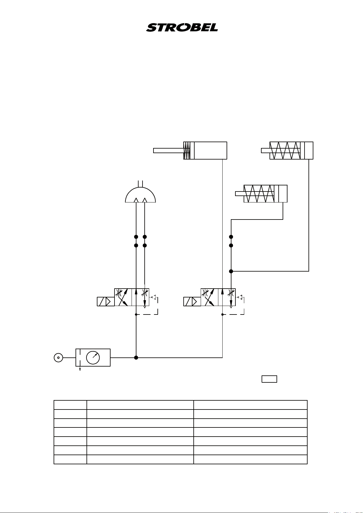
259.00.57
Pneumatischer Schaltplan Kl. 560 ab Ausf. 4
Pneumatic circuit diagram cl. 560 as of version 4
Am Maschinendeckel
(Buchse und Schläuche
kennzeichnen)
on the machine cover
(mark bush and tubes)
1 V 1
1 M 1
A
B
B A
B
A
P R
1 V 2
1 A 3
B
P R
1 A 2
1 A 1
4
A
10bar max
0 Z 1 Wartungseinheit service unit
1 V 1 4/2-Magnetventil "Lüftung" 4/2-solenoid-way valve "lifting"
1 V 2 4/2-Magnetventil "Fadenzieher" 4/2-solenoid-way valve "thread wiper"
1 A 1 Zylinder "Fadenzieher" cylinder "thread wiper"
1 A 2 Zylinder "Fadenspannung" cylinder "thread tension"
1 A 3 Zylinder "Zusatz-Fadenspannung" cylinder "optional thread tension"
1 M 1 Schwenkantrieb "Lüftung" swivel drive "lifting"
0 Z 1
6bar
195.0535
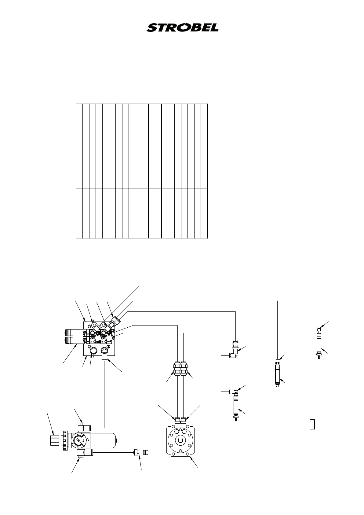
259.10.57en
Pneumatic construction circuit diagram cl. 560 from version 4
193.0473 2600 PA hose Ø6
193.0478 3000 PA hose Ø8
196.0716 3200 PA hose Ø4
293.0469 1 silencer R1/8
293.0772 2 lock screw R1/8
293.0837 2 L-threaded connection R1/8-4
293.0838 1 Y-plug connection 4
293.0850 3 L-threaded connection R1/8-6
293.0852 2 threaded connection R1/8-6
293.0853 1 L-threaded connection M5-4
293.0857 2 threaded connection M5-4
293.0975 1 service unit
293.0976 2 bulkhead union 6
293.0980 1 L-bulkhead union 4
297.0170 1 coupling Ø8
298.0211 3 miniature cylinder Ø8x12,5
298.0510 2 4/2-solenoid-way valve R1/8
298.0511 1 input module G1/8 left
298.0512 1 input module G1/8 right
298.0678 1 swivel drive
196.0716 Ø4
293.0838
293.08372x
293.07722x
298.0512
r
solenoid valve
p
3
1V2
A
B
1V1
r
p
1
3
193.0473 Ø6
193.0473 Ø6
B
298.0510 2x
298.0511
293.0469
293.08503x
293.0976
293.0975
(293.0850)
193.0473 Ø6
293.0852
193.0473 Ø6 150 lg
193.0473 Ø6 150 lg
196.0716 Ø4
196.0716 Ø4
293.0857
4
293.0980
293.0857
A
298.0211
supplementary thread tension
196.0716 Ø4 430 lg
293.0976
293.0852
thread tension
293.0853
298.0211
thread wiper
298.0211
195.0536
lifting
service unit
(293.0841)
193.0478Ø8 3000 lg
298.0678
297.0170
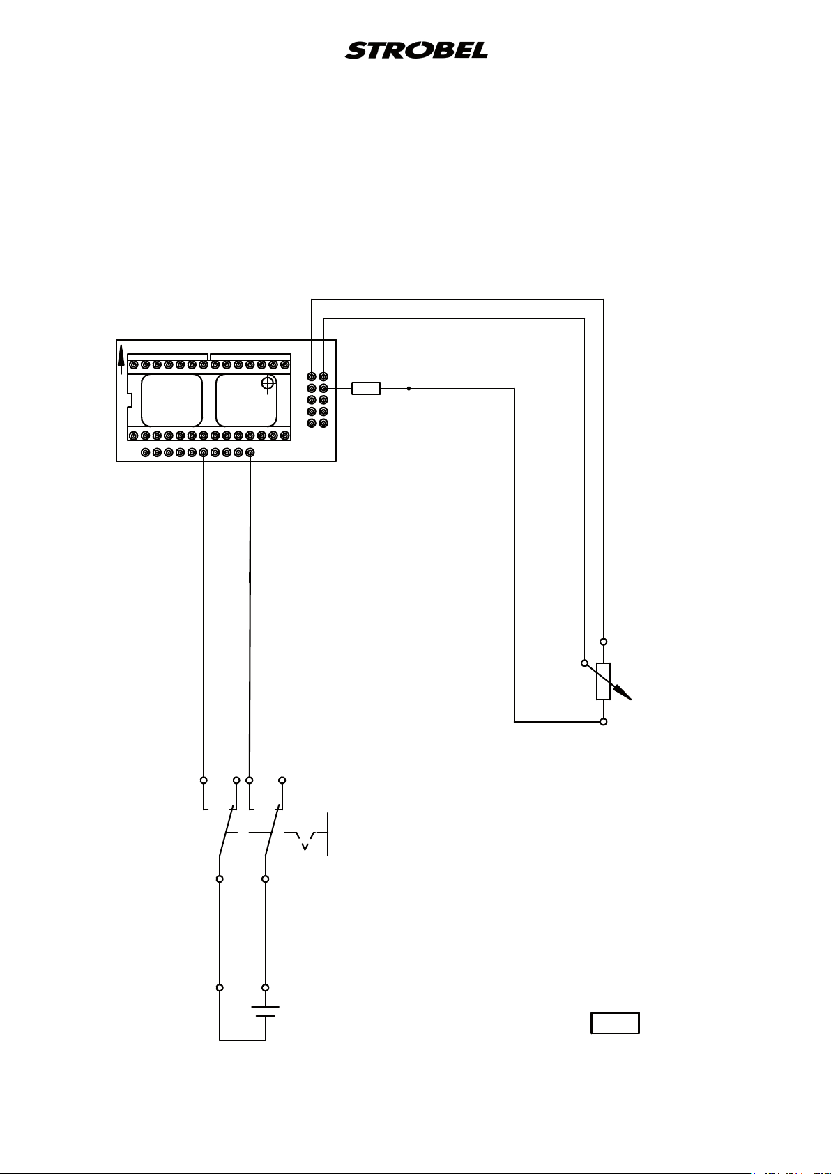
258.21.24
Elektrischer Anschlussplan Kl. 170, 560, ZM
Digitalanzeige
Electric connection diagram cl. 170, 560, ZM
Digital display
Steck-Adapter EA 9044
socket adapter EA 9044
10
VSS
- +
ws / wh
1A
VDD
d
r
/
t
r
1
9 10
B
R2
137kΩ
Widerstand
resistor
ws / wh
gn / gn
br / bn
a
2
R1
5kΩ lin.
b
Drehpotentiometer
rotary potentiometer
1346
Kippschalter
flip switch
k
b
/
w
s
d
r
/
t
r
+
9V
Batterie
battery
198.0466


Und wir können noch mehr für Sie tun!
Unser Lieferprogramm bietet für jede Branche und
jegliche Anforderung genau die richtige Problemlösung.
And we can do a lot more for you!
Our range offers the correct problem solution for
every branch and for all requirements.
Für die Bekleidungsindustrie:
Ein- und ZweifadenHochleistungs-Saummaschinen
DoppelblindstichSaummaschinen
Zweifaden-BlindstichStafermaschinen
Roll- und Flachpikiermaschinen
Pikier-Automat
und
weitere Spezial-Nähmaschinen
For the clothing
industry:
Single and two thread high
performance hemming
machines
Bluff edge hemming machines
Two thread blind stitch felling
machines
Roll and at padding machines
Automatic lapel padding
machine
Für die Schuhverarbeitung:
Einfaden-Überwendlichmaschinen mit und ohne
Differentialtransport
For the shoe industry:
Single-thread overseaming machines with and without differential feed
Für Kürschnereien
und Pelzkonfektion:
Pelzschnellnäher
For the fur industry:
High-speed fur sewing machines
Für Heimtextilien:
Ein- und ZweifadenBlindstichmaschinen
For the home textiles
industry:
Single and two thread
blind stitch machines
Für die Polsterverarbeitung:
Ein- und ZweifadenÜberwendlichmaschinen
Ein- und ZweifadenBlindstichmaschinen
For the upholstery
industry:
Single and two thread
overseaming machines
Single and two thread
blind stitch machines
Für die Konfektion
technischer Textilien:
Ein- und ZweifadenÜberwendlichmaschinen
For the processing
of technical textiles:
Single and two thread
overseaming machines
and other special sewing
machines

Noch Fragen?
Dann rufen Sie uns an, schreiben Sie uns oder
kommen Sie einfach bei uns vorbei.
Sie können jederzeit weitere Informationen über
unsere Produkte anfodern oder die StrobelNähmaschinen in unserem Ausstellungsraum live
erleben. Wir freuen uns auf Sie!
Any further questions?
Then phone, write or simply come and see us. You
can have further information about our products at
any time, or experience the Strobel machines live in
our show room. We’re looking forward to meeting you!
Sp ez i al ma s ch in e n Gm b H
Postfach 1242
82168 Puchheim
Siemensstraße 3
82178 Puchheim
DEUTSCHLAND
www.strobel.biz
Telefon: +49 89 80096-0
Telefax: +49 89 80096-190
 Loading...