


For the professional user
Für den professionellen Anwender
Betriebsanleitung
Class:
Klasse:
Model:
Ausführung:
Machine number:
Maschinen-Nr.:
Dated:
Stand:
3200D
1
Operating Instructions
S p e z i a l m a s c h i n e n G m b H

Im Zeichen der Qualität
ou nd the Strobel trademark on every Strobel
machine leaving our works. And with good reason.
This symbol is a guaranteen of the high quality of
our products. Quality which creates trust – trust
in our technology, our service and, not least of all,
in our good name.
ie nden die Strobel-Schutzmarke auf jeder
Strobel-Maschine, die unser Werk verlässt.
Und das aus gutem Grund. Denn dieses Zeichen
garantiert Ihnen die hohe Qualität unserer
Produkte. Qualität, die Vertrauen schafft – in unsere
Technik, unseren Service und nicht zuletzt in unseren
guten Namen.
S
Y
The sign of quality

trobel clients know that they can expect a particularly high standard of performance from our company
and our machines. Now you have settled for one of
our products. For us this is a source of encouragement
and of obligation to Justify your trust.
If you wish to prot from the performance and
efciency of your Strobel machine as long as possible,
exact handling and thorough care is necessary. For this
reason we kindly request that you read the operating
instructions closely. It provides all the information you
need for trouble free operation.
And if you do happen to need a spare part the enclosed
spare parts list gives a complete overview. It is clearly
classied according to components so that you can nd
the required part quickly and easily. In order to avoid
errors we request you to quote machine class, machine
number and part number completely on your spare part
order.
We wish you lots of success in your work with your
new Strobel machine.
S
A decision with future
S p e z i a l m a s c h i n e n G m b H
1 BA_3200D_A1_140203_en

2 BA_3200D_A1_140203_en

3 BA_3200D_A1_140203_en
Operating Instructions
STROBEL Class 3200D
Contents
1 General notes on safety ............................................................................................ 5
2 General ..................................................................................................................... 7
2.1 Operating instructions ..................................................................................... 7
2.2 Class description, machine number and reference position left/right ............. 7
2.3 Machine applications ...................................................................................... 7
2.4 Technical data ................................................................................................ 8
3 Set-up and commissioning ........................................................................................ 9
3.1 Unpacking of the machine .............................................................................. 9
3.2 Setting up the machine (Fig. 1) ...................................................................... 9
3.3 Sense of rotation (Fig. 3) .............................................................................. 12
3.3.1 Tension of the toothed belt (Fig. 4) .................................................. 12
3.3.2 Positions of the machine .................................................................. 13
3.4 Intermediate venting (Fig. 5) ......................................................................... 14
4 Notes on usage ....................................................................................................... 15
4.1 Needles and threads .................................................................................... 15
4.2 Inserting the needle (Fig. 6) .......................................................................... 15
4.3 Threading and thread run (Fig. 7) ................................................................. 16
4.3.1 Threading the reel thread (Fig. 8) .................................................... 17
4.4 Thread tensioning (Fig. 6) ............................................................................ 18
4.4.1 Thread tightening spring – needle thread (Fig. 9) ............................ 18
4.4.2 Thread tensioning – reel thread (Fig. 10) ......................................... 18
4.5 Winding up the thread (Fig. 11) .................................................................... 19
4.6 Adjusting the stitch length (Fig. 11 and Fi g. 12) ........................................... 20
4.6.1 Adjusting the upper feed path (Fig. 6) .............................................. 20
4.7 Stitch depth ................................................................................................... 21
4.7.1 Adjusting the stitch depth (Fig. 2 and Fig. 6) .................................... 21
4.7.2 Digital stitch depth display (Fig. 13) ................................................. 21
4.7.3 Changing the battery (fig. 13) ........................................................... 22
4.8 Plunger stop ................................................................................................. 23
4.8.1 Adjusting the plunger stop (Fig. 14) ................................................. 23
4.9 Interval gear .................................................................................................. 24
4.10 Sewing drive ................................................................................................. 24

4 BA_3200D_A1_140203_en
5 Operating the sewing machine ................................................................................ 25
5.1 Switch-on ...................................................................................................... 25
5.2 Inserting and removing the sewing material – work sequence ..................... 26
5.3 Sewing .......................................................................................................... 27
5.3.1 Hemming with blind stitch ................................................................ 28
5.4 Problems during sewing and troubleshooting ............................................... 29
5.5 Incorrect stitches (Fig. 17) ............................................................................ 32
6 Machine maintenance ............................................................................................. 33
6.1 Lubricants ..................................................................................................... 33
Subject to change without prior notice

5 BA_3200D_A1_140203_en
1
The non-compliance with the foll owing notes on safety can lead to bodily
injuries or to damages of the machine.
General notes on safety
1. The machine must only be operated by persons familiar with the relevant
operating instructions and who have been instructed accordingly.
2. Before commissioning also read the notes on safety and the operating
instructions of the sewing drive manufacturer.
3. The machine must only be operated according to its designation and not
without the appropriate guards; all explicit safety regulations must also be
observed.
4. For threading, for changing the reels, for exchanging sewing tools such as
needles, hooks, stitch plate, transport devices, if necessary cutter and
cutting block, for cleaning, when leaving the workplace and for
maintenance work, switch off main switch or pull mains plug. With a
mechanically operated coupling motor without activation lock, wait until the
motor has stopped.
5. General maintenance work must only be carried out by appropriately
instructed persons in accordance with the operating instructions.
6. Repair, modification and maintenance work must only be carried out by
qualified staff or by appropriately instructed persons.
7. During maintenance and repair work at pneumatic devices, the machine
must be disconnected from the pneumatic supply network. Exceptions are
only admissible during adjusting work and function test by appropriately
instructed qualified staff.
8. Work at the electrical equipment must only be carried out by qualified
staff.
9. Work at parts and devices under voltage is not allowed. Exceptions are
regulated by the regulation EN50110 (DIN VDE0105).
10. Modification or alteration at the machine must only be undertaken under
consideration of all explicit safety regulations.
11. Only spare parts released by us for use are to be used during repairs.
12. The commissioning of the upper part is prohibited until it has been
determined that the entire sewing unit complies with the regulations of the
EC guidelines.

6 BA_3200D_A1_140203_en
13. Warning notes in the operating instructions of the machine, which point
out special points of danger, are marked at the appropriate positions with
the safety symbol.
Warning notes in the operating instructions of the machine which point out
special dangers of injury for operating or qualified staff, are marked at the
appropriate positions with the symbol
It is essential that you observe and follow these notes as well as the
generally valid safety regulations.

7 BA_3200D_A1_140203_en
2
2.1
General
Any person involved in the installation, operation, maintenance and repair of
the machine must have read and understood the operating instructions and
mainly the safety instructions before starting the machine.
Operating instructions
2.2
For side-referenced descriptions (right, left), the operating side of the machine
is the starting base.
The class identification (type) is in front, the machine and model number (after
the dash) is on the upper right under the cover on the housing.
These data are also noted on the machine number on the front of the cover
page of the operating instructions.
Class description, machine number a nd reference position
left/right
2.3
Kl. 3200D
Machine appli c a t ions
Two thread blind stitch double lock stitch machine provides a high-quality
processing of edges in the field of women's clothing. The special procedure
using the world's unique machine class 3200D the edge may be piping, without
showing a visible seam. This is located 2 mm below the edge piping. Between
the fabric and tape.
The 2-thread lockstitch blind stitched seam guarantees both. The safety as well
as the required elasticity.
Two spring loaded plungers enable passing the cross seams without any
markings on the outside.
The machine has been designed specifically for fine and finest fabrics of
women's clothing.

8 BA_3200D_A1_140203_en
2.4
Speed:
Technical data
Max. mechanically admissible 1200 min-1
Recommanded rated speed 1200 min-1
Min. motor power 0.37 KW
Compact drive:
Toothed belt pulley/machine z = 38
Toothed belt profile HTD 5M-9
Stitch length-upper feed 2 - 6 mm
Kind of stitch: two thread blind stitch lock stitch
Stitch type 313
Needle system STROBEL 1828 E
Needle size 70, 80, 90
Recommended thread twisted polyester filament
Recommended thread size 120/2, 200/2
Air pressure 6 bar
Average air consumption 0.31 l per work stroke
Foot print 0.6 m x 1.1 m
Noise:
Average noise level at a speed of
n = 1200 min-1: LpAm 74.9 dB(A)
Noise test according to DIN 45635-48-1 KL3

9 BA_3200D_A1_140203_en
3
3.1
Set-up and commissioning
Strobel machines are supplied either complete as upper part with motor or as
upper part only.
Unpacking of the machine
With complete delivery the machines are subdivided in smaller packing units
due to the great weight and to prevent transport damages.
The upper part is unscrewed form the frame. The cotton stands, rod system, oil
and further machine accessories are located in the frame packing.
Prior to disposing of the packing material it must be carefully checked whether
all accessories parts have been unpacked.
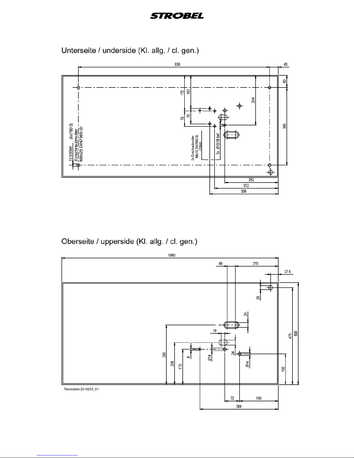
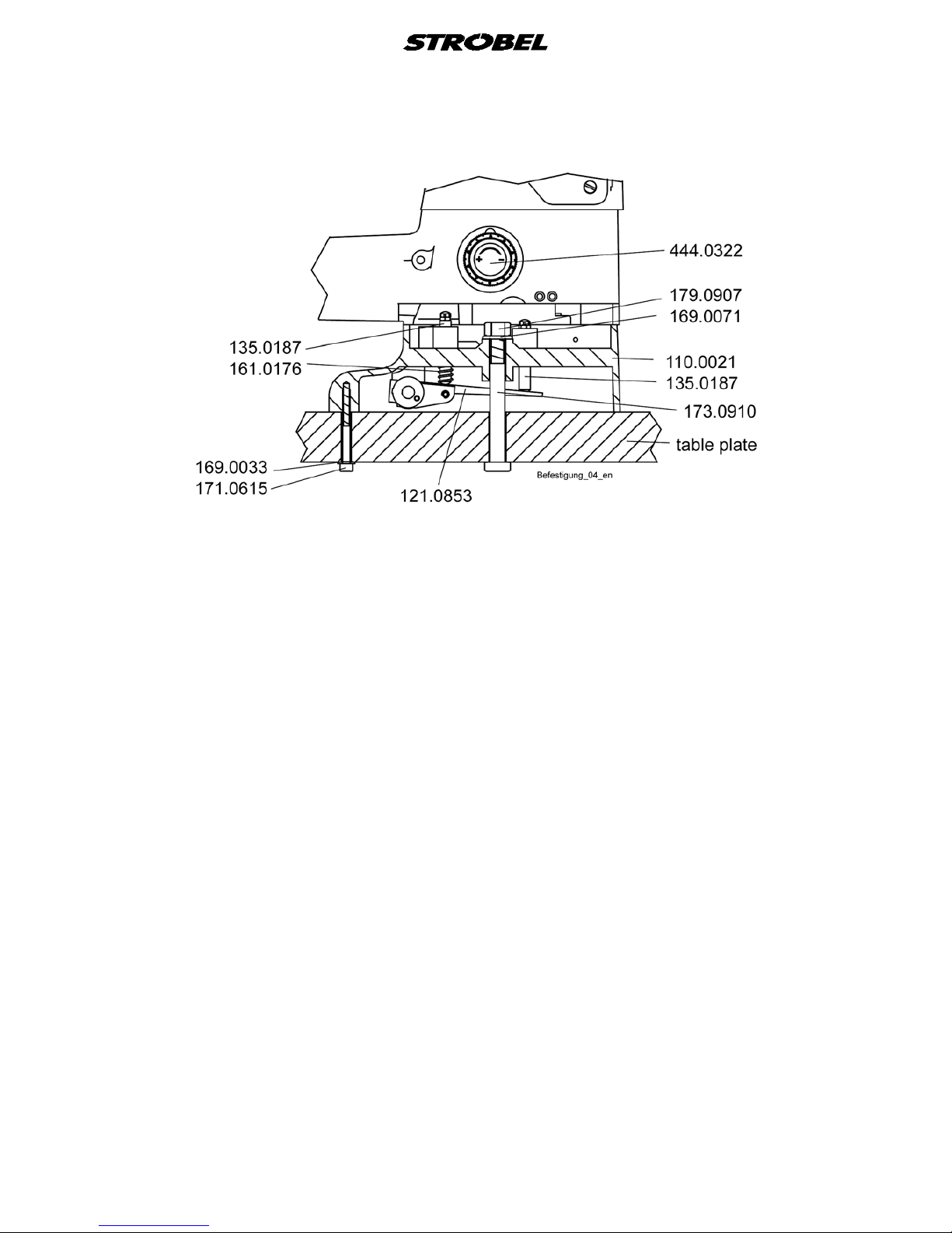
3.2
Setting up the machine ( Fig. 1)
CAUTION! Danger of injury!
Due to pulling in of parts of clothing or hair as well as
danger of crushing of fingers!
The machine must not be operated without a guard for the
belt for the upper part and for the motor.
Screw the upper part to the table plate. (Fig. 2)
The bolts 135.0187 and the pressure spring 161.0176 are enclosed with the
machine accessories and must be fitted as shown in Fig. 2.
The pedal rod system must be suspended according to Fig. 1
.
Push on the knee lever and secure with knurled screw. (not necessary with
pneumatic venting, see also point “3.5 Intermediate venting (Fig. 5)”)
The cotton stand is mounted at the back on the right on the table plate after
assembly of the individual parts.
Check all screws at the frame for tight fit and retighten if necessary.
ATTENTION!
Prior to commissioning the machine it must be checked
whether the electric connection data on the type plate of the
motor, especially the network voltage and the frequency,
are according to the data of your current network.
All rust prevention agents, such as Vaseline or similar, must be carefully
removed from the sewing tools prior to commissioning the machine.

10 BA_3200D_A1_140203_en
Fig. 1
Class 3200D
11 BA_3200D_A1_140203_en
Fig. 2

12 BA_3200D_A1_140203_en
3.3
The correct sense of rotation of the hand wheel is clockwise when looking at it
from the front.
Sense of rotation (Fig. 3)
Fig. 3
3.3.1
Tension of the toothed bel t (Fig. 4)
CAUTION! Danger of injury!
To check the tension of the toothed belt, switch off the
machine electrically, pull the mains plug and ensure the
machine has actually stopped by pressing the motor pedal.
The machine must not be operated without a belt guard for
the motor.
The tension of the toothed belt should not be too great. Slight thumb pressure
should be able to push the belt through by approx. 10 mm.
A too little or too great toothed belt tension can deteriorate the positioning of the
machine and therefore impair the function sequence.
Tensioning the toothed belt (Fig. 4):
- Release upper and lower retaining screw (1), (2) at the machine upper
part.
- Pull out the motor slightly and tighten the lower retaining screw (2) slightly.
- Tension the toothed belt by swivelling the motor.
- Retighten the upper and lower retaining screw (1), (2).

13 BA_3200D_A1_140203_en
Fig. 4
3.3.2
Positions of the mac hine
CAUTION! Danger of injury!
Danger of pulling in parts of clothing and of hair and danger
of crushing fingers and stitching fingers with needles!
When checking positions with switched-on machine keep
fingers and hands away from moving parts.
Machine with or without pneumatic:
The machine requires a needle position and depending on the sewing drive,
possibly also a reference position.
Reference position (if necessary, i.e. sewing drive DC1500-ST220A):
The reference position must be set in such a way, that the point of the
needle in direction of the insertion stitch closes with the (inner) edge of the
needle slide plate.
Needle position (with stop in and outside the seam:
The needle position needs to be set in such a way that when the machine
is at standstill and the lifting is open the tip of the needle points in the
direction of the stitch and the plunger, transporter, and presser plate are at
one level (the position is located at about 8 mm after the upper needle
turning point).
Notes for sewing drives which have two needle positions:
The needle position mentioned above is position 2 at the sewing drive.
The position 1 at the sewing drive should be set in such a way that when
the machine is at standstill the tip of the needle stands about 3 mm in the
direction of the stitch after the lower needle turning point.

14 BA_3200D_A1_140203_en
3.4
If an intermediate venting with the knee lever should become necessary with
attached pneumatic venting, it can be mounted on the screw 130.0041 in its
usual position.
Intermediate venting (Fig. 5)
Fig. 5
15 BA_3200D_A1_140203_en
4
4.1
Notes on usage
By selecting the most suitable needles and threads for the relevant sewing
material one can influence the sewing quality decisively.
Only tested STROBEL needle system 1828 E should be used.
The machine is supplied with needles of thickness 90.
Needle thicknesses 70 and 80 are also available.
Needles and threads
Note: An intact needle is of decisive importance for a good initial stitch.
Bent needle points, which can in part only be visible under a
magnifying glass, impair the sewing result.
Therefore, exchange your needles in good time!
We recommend endless twined polyester threads with a thickness of 120/2 or
200/2. They are to be preferred to a spun thread, due to their high strength and
good sliding ability at low thread volume.
Guaranteed remark!
This machine has been set and sewn off with genuine
Strobel needles.
No guarantee can be granted if the settings are modified
for using different needle types.
4.2
Inserting the needle (Fig. 6)
CAUTION! Danger of injury!
Switch off the machine before changing the needle and
ensure the machine is off by pressing the pedal for
switching the motor. Otherwise there is a danger of injury
through crushing and needle stitches.
Due to the bent shape of the needle the position in the needle lever is given.
Care must only be taken that the needle piston is pushed in the slot of the
needle lever up to the stop and that the needle clamping plate 485.0009 is
tightened with the screw 170.0438.

16 BA_3200D_A1_140203_en
Fig. 6
4.3
Threading and thread r un ( Fig. 7)
CAUTION! Danger of injury!
Switch off the machine prior to threading and ensure the
machine is off by pressing the pedal for switching the
motor.
Fig. 7 shows the correct threading by using the thread sensor.

17 BA_3200D_A1_140203_en
Fig. 7
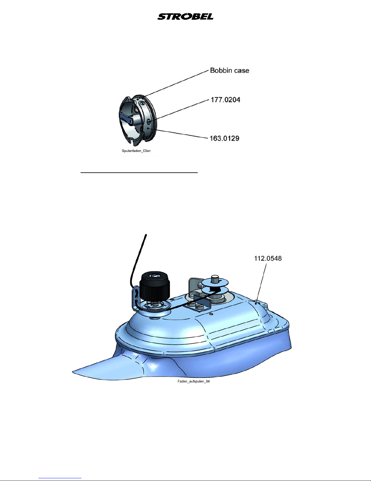
4.3.1
By turning the needle lever to its highest position with the hand wheel, the reel
187.0013 can be taken out and reinserted. Fold the reel holder flap away from
the reel capsule with a short jerk, the reel then jumps by spring pressure out of
the reel capsule so that it can be easily removed.
Threading the reel t hread (Fig. 8)
When inserting the reel take care that the reel thread unwinds from the
underside of the reel. Then guide the start of the reel thread through the slot at
the right hand side of the reel capsule and hold it lightly at the stitch plate.
Then turn the hand wheel of the machine a full rotation and at the same time
hold the needle thread lightly tensioned after take up by the hook point. This
pulls the reel thread correctly under the leaf spring.
It is best to then lightly twist together the needle thread and the reel thread and
pull them together to the back through the stitch plate hole.

18 BA_3200D_A1_140203_en
Fig. 8
4.4
Dependent on grade, characteristic and thickness of the thread as well as the
sewing material, the thread tensioning is adjusted to the required seam diagram
with the tensioning nut 279.0624.
Thread tensioning (Fig. 6)
4.4.1
The tension of the rotary spring 163.0008 can be modified after releasing the
grub screw 176.0406 and by turning at the headed bolt 136.0010. It starts to
tension the thread when the thread loop is approx. 15° in front of the upper
point of the hook, that is, before it can fall off to the right of the hook.
Thread tightening spr ing – needle thread (Fig. 9)
Fig. 9
4.4.2
The leaf spring 163.0021 regulates the reel thread tension.
By turning the flat head screw with the catch 177.0204, the leaf spring must be
able to be adjusted in such a way that when the reel is inserted and the thread
is pulled underneath the leaf spring correctly and then the reel capsule is
released, the reel capsule together with the reel falls slowly down, or by slight
pulling at the thread.
Thread tensioning – ree l thr ead (Fig. 10)
19 BA_3200D_A1_140203_en
Fig. 10
4.5
The course of the thread during winding up is shown in
Winding up the thread (Fig. 11)
Fig. 11.
Care must be taken that not too much of the thread is wound onto the reel and
that the reel walls are not pushed apart, faulty reels must immediately be
replaced with new ones.
Fig. 11

20 BA_3200D_A1_140203_en
4.6
Adjusting the stitch length (Fig. 11 and Fig. 12)
CAUTION! Danger of injury!
Switch off the machine and ensure it is switched off by
pressing the pedal for switching the motor.
Otherwise there is a danger of injury through crushing and
needle stitches.
The stitch length can be adjusted after lifting the cover 112.0548 (Fig. 11).
First release grub screw 176.0413, then turn cheese-head screw 170.0507 to
the left, the stitch length becomes larger, or to the right, the stitch length
becomes smaller (Fig. 12).
After adjusting the required stitch lengths, retighten the grub screw 176.0413.
Fig. 12
4.6.1
By activating the right pedal the upper feed path is enlarged, that is, multi-width
can be worked in.
By turning the knurled screw 177.0634 to the left, multi-width can be worked in
continuously.
Adjusting the upper feed pat h ( Fig. 6)

21 BA_3200D_A1_140203_en
4.7
By stitch depth one understand the distance of the highest plunger position to
the outside radius of the needle, the plunger presses the sewing material from
underneath in the stitch plate opening, so that the needle stitches into the fabric
layers at the required depth.
Stitch depth
Low stitch depth: the needle penetrates less deep into the fabric layers
of the sewing material.
Large stitch depth: the needle penetrates deeper into the fabric layers of
the sewing material.
With too low or too large a stitch depth, omissions or through-stitches can
occur.
4.7.1
With the aid of the stitch depth regulating button 444.0322 (
Adjusting the stitch depth (Fig. 2 and Fig. 6)
Fig. 1) on the lower
arm on the right, the plunger can be lifted or lowered dependant on the
thickness of the fabric. Above this regulation button is a plate which shows how
the button must be turned so that the plunger is lowered or lifted.
Turning the button to the right – plunger goes upward, needle penetrates
deeper.
Turning the button to the left – plunger goes downward, needle
penetrates less deep
See also “4.7.2 Digital stitch depth display (Fig. 13)”.
The stitch depth for the side plunger is adjusted with the knurled screw
177.0418 (Fig. 6) on the left above the stitch plate.
Turning to the front (clockwise) – needle penetrates deeper
Turning to the back (anti-clockwise) – needle penetrates less deep.
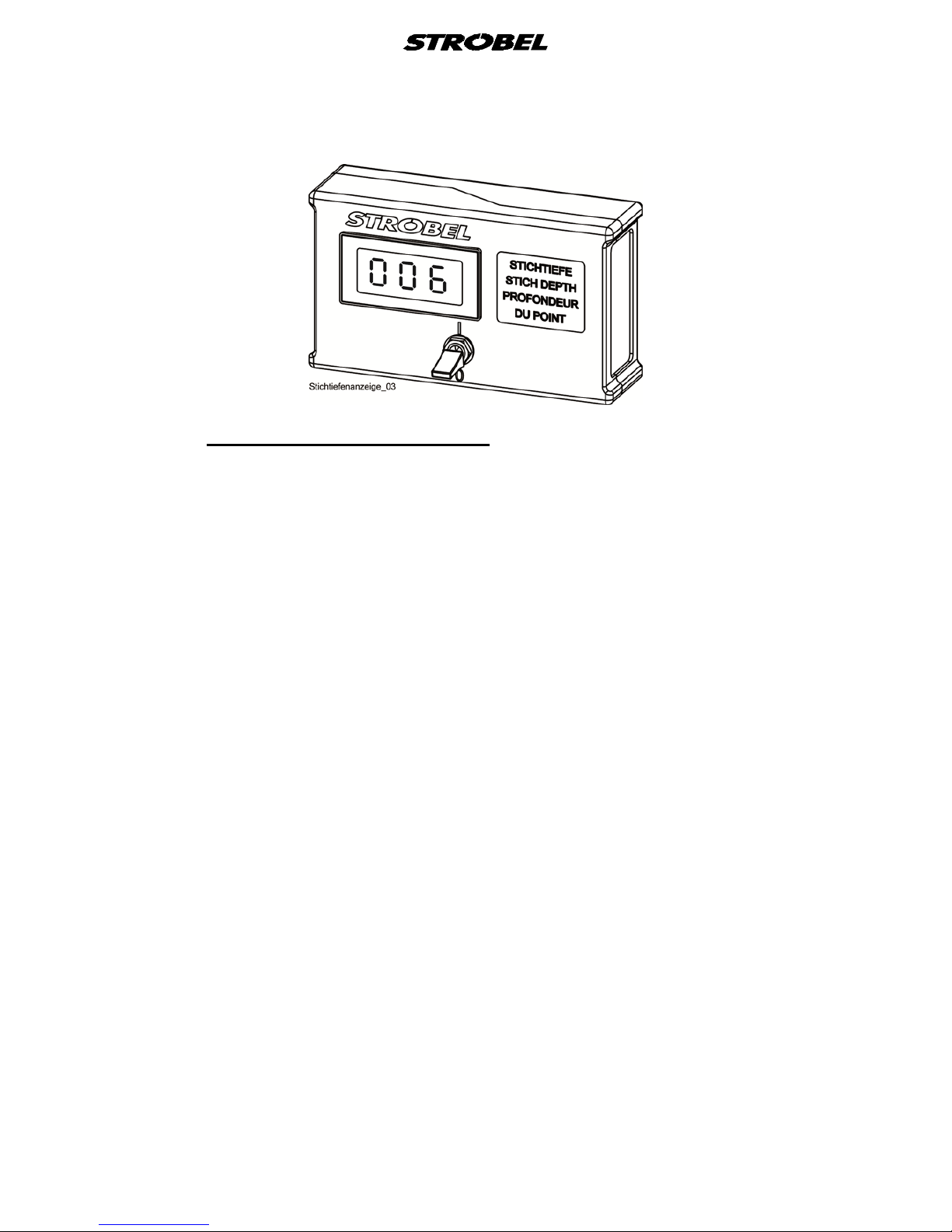
4.7.2
The plunger height can be read off digitally from the stitch depth display. This
makes finding earlier adjustments substantially easier by frequently changing
sewing material thickness.
Digital stit c h de pt h display (Fig. 13)
The current supply is via a 9 V battery in the housing. To prevent premature
discharging of the battery, the display should be switched off with the toggle
switch at the housing during longer work breaks and when finishing work.
The unit shows a hundredth of a mm, the hundred position a full rotation of the
regulating button.
Always valid: Small number - thin sewing material
Large number - thick sewing material
The adjustment of the stitch depth by one digit (= 1 point of the display unit) is
equal to a plunger height modification of 0.01 mm.
When turning the regulating button to the right to the stop a value between 003
and 006 appears on the display.
22 BA_3200D_A1_140203_en
Fig. 13
4.7.3
a) Switch the toggle switch to position 0
Changing the battery (fig. 13)
b) Release 4 cheese-head screws with cross-slot at the back of the housing
c) Remove front part of the housing
d) Change battery. CAUTION! Take note of polarity.
e) Reassemble in reverse order.

23 BA_3200D_A1_140203_en
4.8
Frequently it is necessary when trimming fabric to sew over different fabric
thicknesses at the same work piece, whereby the penetration depth of the
needle, viewed from the upper side of the sewing material, must always remain
the same.
Plunger stop
The plunger built- into our machines carries out this work automatically in
cooperation with an adjustable plunger stop mounted on the stitch plate.
4.8.1
Adjusting the plunger stop (Fig. 14)
CAUTION! Danger of injury!
When adjusting in the area of the stitch plate there is
danger of injury, especially a danger of crushing fingers due
to accidental activation of the pedals!
First set the plunger with the stitch depth regulation button so high that the
required thickness of the sewing material, in most cases the outside fabric, is
stitched blind satisfactory.
Then the plunger stop supported on the stitch plate is adjusted with the knurled
screw (partly also hexagon nut) in such a way, that the sewing material is
pressed from above onto the plunger.
Now the plunger, under pressure from a spring, can rise above several layers of
fabric, cross seams, thickenings etc lying above each other only to such a
height, that the upper fabric layers and not the outside fabric is stitched.
The above adjustment requires some technical knowledge and experience.
Care must be taken that the pressure spring 161.0157 is only adjusted as much
as is necessary for the correct effect of the plunger stop. This keeps the
pressure of the plunger onto the plunger stop as low as possible and less stress
is put on stitch plate and machine.
With adjustment of the plunger pressure at the works, the screw for the plunger
regulation 177.0609 is flush with the plunger guide 253.0048.
By turning the plunger adjusting screw 177.0303, including the screw for the
plunger regulation 177.0609, to the right it increases, to the left it decreases.

24 BA_3200D_A1_140203_en
Fig. 14
4.9
The interval 1:2 guarantees an elastic seam almost free of marking with
extremely difficult to work fabric qualities.
Interval gear
The principle of the interval is based on the repeat of a different plunger height,
which always remains the same with the individual penetrations of the needle.
We use it with two different machine types:
a) Needle lever with radial movement.
The needle stitches the outside or hemming of edge piping with each
second (1:2) rotation of the machine. With the other rotations the
penetration is carried out only in the upper fabric layers.
b) Needle lever with radial movement – for straight stitch-machine.
The interval 1:2 enables the needle in each case to make in the upper
fabric and in the inside lining penetration
The difference of the plunger height between the individual stitches is partly
fixed set or stepless adjustable from 0 to + (=maximum approx. 0.2 mm).
4.10
The machine is as a rule equipped with the sewing drive selected by you.
Sewing dr ive
Please note the separately enclosed operating instructions for the sewing drive.
There you find notes and the instructions for programming the control including
the motor speed adjustments.

25 BA_3200D_A1_140203_en
5
Operating the sewing machine
CAUTION! Danger of injury!
Take sufficient care during sewing and observe the sewing
area!
Otherwise there is a danger of injury through crushing and
needle through-stitches.
The number of stitches depends on the setting of the pedal to the motor
control.
With machines with two pedals the upper transport length is lengthened when
pressing the right pedal (multi-width work-in).
The motor control is taken over by the left pedal in this setting.
To vent the machine, a pneumatic venting can be supplied instead of the knee
lever.
By back-pedalling the pedal for control of the motor the machine travels to its
position and vents pneumatically.
Due to the pressure of the pedal towards the front, the venting closes and the
machine starts to sew.
Normal setting of the pedal:
1. after venting: venting open
2. after sewing: venting closed
5.1
Switch on the main switch on the right underneath the table plate, control lamp
lights up.
Switch-on
With pneumatic venting, connect the maintenance device to the compressed air
network (10 bar) or connect the compressor and regulate to 5 – 6 bar.
The venting is now opened and the sewing machine is ready for operation.

26 BA_3200D_A1_140203_en
5.2
When during standstill of the machine the needle is approx. 15 mm after its
upper dead point in front of the penetration, the presser plate and the plunger
can be moved downwards by activating the knee lever. At the same time the
needle thread tension is vented.
Inserting and rem ovi ng t he s e wing mater ial – work sequence
For pneumatic venting also see point “5 Operating the sewing machine”.
Now the sewing material can be inserted into the machine between stitch plate
and presser plate.
The sewing material cannot be removed until the last stitch has been
completely carried out, the needle thread loop has dropped from the hook, the
needle is again in the position mentioned above and the knee lever is activated.
When using a sewing drive with needle height position, the positioning is
carried out automatically.
CAUTION IMPORTANT!
Do not let the machine run if there is no fabric between stitch plate and
transporter.
27 BA_3200D_A1_140203_en
5.3
The piped edge will be inserted into the left side of the stitch plate in vertical
position.
Sewing
The garment is at the right side of the needle.
Fig. 15
Fig. 16

28 BA_3200D_A1_140203_en
5.3.1
If there are no experience values available, the best thing to do is to carry out
the following settings in sequence:
Hemming with blind stitch
1. Adjust required stitch length
2. Adjust stitch depth
3. Check plunger stop and if necessary adjust
4. Adjust material guide (if available)
5. Check presser plate lift. (Mechanic's instructions)
6. Check stitch length.
7. Adjust thread tension, the seam should lie loose on the hem as a rule.
8 If necessary switch on interval and, dependant on the thickness of the
sewing material, adjust interval stroke.
9. Correct the seam diagram.
Insert the sewing material and take care that the start of the hem can be
taken up by the transporter after the first stitch.
Check the sewing result achieved and possibly modify the adjustments
carried out above.
With through stitches or omissions at the outside fabric (right hand initial
stitch) or the hem edge or the lining (left hand initial stitch), adjust the
stitch depth settings.
„Markings“ caused by the penetration of the needle in the outside fabric
(shift of fibres) sometimes cannot be avoided with extremely thin und hard
sewing material.
When sewing take care that the hem edge always runs along the material
guide (if available). Jerky activation of the pedal should be avoided, as
changes in speed during the sewing process can under certain
circumstances have a negative effect on the initial stitch.
NOTE: To avoid having a build-up with thick fabrics it is recommend to
cut off the corners at the cross seams prior to hemming.

29 BA_3200D_A1_140203_en
5.4
Problems during s ewing and troubleshooting
CAUTION! Danger of injury!
Switch off the machine and ensure it is switched off by
pressing the pedal for switching the motor.
Otherwise there is a danger of injury through crushing and
needle stitches.
• Thread tearing
Possible causes:
- Sharp edges or grooves in the needle guide, thread sensor, hook or
needle eye after long use of the machine
- The thread between hook and reel capsule breaks or it is pinched
off.
- Too much oil has got into the hook path
- The reel runs to tight, or the reel walls are pushed apart by too tightly
wound thread
- The reel capsule venting or hook bridge are not adjusted correctly
- The hook to the needle or the loop lift has not been adjusted
correctly or it has slipped and therefore the thread loop is not always
taken up.
- The thread tension is too slack or too tight adjusted.
Remedy:
- Replacing or repolishing of the damaged parts.
- Dismount hook, remove reel capsule and polish inlet edges of the
reel capsule and the hook path.
- Sew out on a fabric rest with an absorbent thread (cotton thread,
wrapping cotton).
- Insert new reel
- Turn the machine through slowly manually and check whether the
loop slides over the hook unimpaired, if not, readjust reel capsule
venting or hook bridge.
- Correct hook position or loop stroke
- Correct thread tension, check thread run
Please observe: thread course, thread, needle plate with presser and
cloth retainer, needle and thread tension should always
be set and chosen according to the material to be
sewn.

30 BA_3200D_A1_140203_en
• Inaccurate initial stitch
Possible causes:
- Frequently worn or damaged needle
- Stitch plate or needle slide plate incorrect adjusted in height
- Unsuitable needle thickness
Remedy:
- replace damaged needle, check settings, if necessary correct,
correct needle thickness
• Missing loops
Most frequent causes:
- Incorrect adjusted or displaced hook
- Loop stroke too small
Remedy:
- turn machine trough manually, check hook movement
Usually the cause can be observed.
- Maybe also correct thread tension or thread tension spring
- Correct loop stroke
• Loops stop (hook knits)
Most frequent causes:
- Thread tension too slack
Remedy:
- Check thread tension or thread tightening spring
• Machine does not start
Possible causes:
- Error in the control
- Mechanical damage
Remedy:
- Switch machine off and on
- Eliminate mechanical error
- Check programming. If necessary call service.

31 BA_3200D_A1_140203_en
• The sewing result is not according to your expectations
Possible causes:
- Damaged sewing tools or wear due to improper use or natural wear
after longer use of the machine.
- Machine has displaced itself mechanically
- Unsuitable needle thickness (see point “4.1 Needles and threads”)
- Unsuitable sewing thread (see point “4.1 Needles and threads”)
Remedy:
- Exchange damaged parts, service
- With mechanic; see also mechanic’s instructions; maybe call service
- Exchange needle, check also needle point as to damage
• Marking or damage to the sewing material
Possible causes:
- Unsuitable transporter – gear
- Incorrect setting of the sewing tools
- Damaged sewing tools
- Unsuitable needle thickness or thread thickness
Remedy:
- Check settings
- Check transporter (gear), if necessary exchange transporter
- Select correct needle and thread for sewing material
• Difficulties when transporting the sewing material (stitch length)
Possible causes:
- Transporter is incorrectly set
- Unsuitable transporter – gear
- Incorrect presser plate lift
- A sewing material build-up in the stitch plate, especially with cross
seams
Remedy:
- Check settings, if necessary change transporter
- Check stitch plate underside, transport tools and sewing tools for
damages, if necessary replace or repolish

32 BA_3200D_A1_140203_en
5.5
The correct two-thread blind stitch is shown in
Incorrect stitches (Fig. 17)
Fig. 17.
Incorrect stitches can occur if the needle does not take up the sewing material
or does not carry out initial stitch or the hook does not take up the thread loop.
Fig. 17

33 BA_3200D_A1_140203_en
6
Machine maintenance
CAUTION! Danger of injury!
Disconnect the machine from the mains and ensure that it
is off by pressing the pedal for switching the motor.
Otherwise there is a danger of injury through crushing and
needle stitches.
The machine must be oiled daily at the points marked red (oil bottle is included
with the machine accessories). For this remove the housing cover on the right
top, the under arm cover bottom left and the head hood.
Fabric fibres and dirt which collect at the movable parts of the machine must be
removed, as they could cause errors and impair the operating safety.
The hook path should also be oiled from time to time with a drop of oil, there is
a bore for this in the hook cover.
6.1
For oiling the machine only oil with a viscosity of 46 cSt must be used and can
be purchased with the following part number:
Lubricants
291.0107 oil with can 0.5 litre


Und wir können noch mehr für Sie tun!
And we can do a lot more for you!
Unser Lieferprogramm bietet für jede Branche und
jegliche Anforderung genau die richtige Problemlösung.
Our range offers the correct problem solution for
every branch and for all requirements.
Für die Bekleidungsindustrie:
Für die Schuhverarbeitung:
Für die Polsterverarbeitung:
Ein- und ZweifadenHochleistungs-Saummaschinen
DoppelblindstichSaummaschinen
Zweifaden-Blindstich-
Stafermaschinen
Roll- und Flachpikiermaschinen
Pikier-Automat
und
weitere Spezial-Nähmaschinen
Einfaden-Überwendlichmaschinen mit und ohne
Differentialtransport
Ein- und ZweifadenÜberwendlichmaschinen
Ein- und ZweifadenBlindstichmaschinen
For the clothing
industry:
Single an two thread high
performance hemming
machines
Bluff edge hemming machines
Two thread blind stitch felling
machines
Roll and at padding machines
Automatic lapel padding
machine
and other special sewing
machines
For the shoe industry:
Single-thread overseaming
machines with and without
differential feed
Für Kürschnereien
und Pelzkonfektion:
Pelzschnellnäher
Pelzpikiermaschine
Futterstafermaschine
For the fur industry:
Rapid fur sewing machines
Fur padding machine
Lining felling machine
Für Heimtextilien:
Ein- und ZweifadenBlindstichmaschinen
For the home textiles
industry:
Single and two thread
blind stitch machines
For the upholstery
industry:
Single and two thread
overseaming machines
Single and two thread
blind stitch machines
Für die Konfektion
technischer Textilien:
Ein- und ZweifadenÜberwendlichmaschinen
For the processing
of technical textiles:
Single and two thread
overseaming machines

Noch Fragen?
Any further questions?
Dann rufen Sie uns an, schreiben Sie uns oder
kommen Sie einfach bei uns vorbei.
Sie können jederzeit weitere Informationen über
unsere Produkte anfodern oder die StrobelNähmaschinen in unserem Ausstellungsraum live
erleben. Wir freuen uns auf Sie!
Then phone, write or simply come and see us. You
can have further information about our products at
any time, or experience the Strobel machines live in
our show room. We’re looking forward to meeting you!
S pe z ia l ma s ch i ne n G m bH
Postfach 1242
82168 Puchheim
Siemensstraße 3
82178 Puchheim
DEUTSCHLAND
www.strobel.biz
Telefon: +49 89 80096-0
Telefax: +49 89 80096-190
 Loading...