


For the professional user
Operating Instructions
Für den professionellen Anwender
Betriebsanleitung
Class:
Klasse:
Dated:
Stand:
310D-R Ausf. 16
3100D-R Ausf. 3
Spezialmaschinen GmbH

The sign of quality
ou nd the Strobel trademark on every Strobel
Y
machine leaving our works. And with good reason.
This symbol is a guarantee of the high quality of
our products. Quality which creates trust – trust
in our technology, our service and, not least of all,
in our good name.
Im Zeichen der Qualität
ie nden die Strobel-Schutzmarke auf jeder
S
Strobel-Maschine, die unser Werk verlässt.
Und das aus gutem Grund. Denn dieses Zeichen
garantiert Ihnen die hohe Qualität unserer
Produkte. Qualität, die Vertrauen schafft – in unsere
Technik, unseren Service und nicht zuletzt in unseren
guten Namen.

A decision with future
trobel clients know that they can expect a particularly
S
high standard of performance from our company and our
machines. Now you have settled for one of our products.
For us this is a source of encouragement and of obligation
to Justify your trust.
If you wish to prot from the performance and efciency of
your Strobel machine as long as possible, exact handling
and thorough care is necessary. For this reason we kindly
request that you read the operating instructions closely.
It provides all the information you need for trouble free
operation.
And if you do happen to need a spare part the enclosed
spare parts list gives a complete overview. It is clearly
classied according to components so that you can nd the
required part quickly and easily. In order to avoid errors we
request you to quote machine class, machine number and
part number completely on your spare part order.
We wish you lots of success in your work with your new
Strobel machine.
Spezialmaschinen GmbH
1 BA_310D-R_3100D-R_A16-3_180117_en

2 BA_310D-R_3100D-R_A16-3_180117_en

Operating Instructions
STROBEL Classes 310D-R and 3100D-R
Contents
1 General notes on safety ............................................................................................ 5
2 General ..................................................................................................................... 7
2.1 Operating instructions ..................................................................................... 7
2.2 Class description, machine number and reference position left/right ............. 7
2.3 Machine applications ...................................................................................... 7
2.4 Technical data ................................................................................................ 8
3 Set-up and commissioning ........................................................................................ 9
3.1 Unpacking of the machine .............................................................................. 9
3.2 Setting up the machine (Fig. 1 and Fig. 2) ...................................................... 9
3.3 Sense of rotation (Fig. 3) .............................................................................. 13
3.4 Motor drive via toothed belt .......................................................................... 13
3.4.1 Tension of the toothed belt (Fig. 4) .................................................. 13
3.4.2 Positions of the machine .................................................................. 14
3.5 Intermediate venting (Fig. 5) ......................................................................... 15
4 Notes on usage ....................................................................................................... 16
4.1 Needles and threads .................................................................................... 16
4.2 Inserting the needle (Fig. 6) .......................................................................... 16
4.3 Threading and thread run (Fig. 7) ................................................................. 17
4.4 Winding up the thread (Fig. 8) ...................................................................... 19
4.4.1 Installing the bobbin and threading the bobbin thread (Fig. 9) ......... 19
4.5 Thread tensioning (Fig. 6) ............................................................................ 20
4.5.1 Thread tightening spring – needle thread (Fig. 10) .......................... 20
4.5.2 Thread tensioning – reel thread (Fig. 11) ......................................... 21
4.6 Adjusting the stitch length (Fig. 8 and Fig. 12) ............................................. 21
4.6.1 Adjusting the upper feed path (Fig. 6) .............................................. 22
4.7 Stitch depth................................................................................................... 23
4.7.1 Adjusting the stitch depth (Fig. 2 and Fig. 6) .................................... 23
4.7.2 Digital stitch depth display (Fig. 13) ................................................. 24
4.7.3 Changing the battery (Fig. 13) ......................................................... 24
4.8 Plunger stop ................................................................................................. 25
4.8.1 Adjusting the plunger stop (Fig. 14) ................................................. 25
4.9 Interval gear .................................................................................................. 26
4.10 Seam lock ..................................................................................................... 27
4.10.1 General ............................................................................................ 27
4.11 Sewing drive ................................................................................................. 27
3 BA_310D-R_3100D-R_A16-3_180117_en

5 Operating the sewing machine ................................................................................ 28
5.1 Switch-on ...................................................................................................... 28
5.2 Inserting and removing the sewing material ................................................. 29
5.3 Sewing .......................................................................................................... 29
5.3.1 Hemming with blind stitc h ................................................................ 30
5.4 Problems during sewing and troubleshooting ............................................... 31
5.5 Incorrect stitches (Fig. 16) ............................................................................ 34
6 Machine maintenance ............................................................................................. 35
7 Variable sewing tools .............................................................................................. 36
8 Optional Extras ........................................................................................................ 41
8.1 Plunger ......................................................................................................... 41
8.2 Additional parts for hemming half lined jackets ............................................ 41
Subject to change without prior notice
4 BA_310D-R_3100D-R_A16-3_180117_en

1 General notes on safety
Every person in charge of setting up, operating, servicing and repairing the
machine must first read and understand the operating instructions and
particularly the safety instructions before starting up the machine.
Failure to comply with the following safety instructions can lead to bodily
injury or damage to the machine.
1. The machine must only be operated by persons familiar with the relevant
operating instructions and who have been instructed accordingly.
2. Before commissioning also read the notes on safety and the operating
instructions of the sewing drive manufacturer.
3. Only use the machine in the intended manner and never without the
provided guards. Always observe the pertinent safety regulations.
4. Switch off the main switch or pull the power plug for threading, changing
the reels, exchanging sewing tools such as needle, gripper, needle plate,
transport devices, possibly cutter and cutting block, for cleaning and when
leaving the workplace as well as for maintenance.
5. General maintenance tasks may be carried out only by properly trained
persons in accordance with the operating instructions.
6. Repair work, retrofitting and maintenance may be carried out only by
technicians or specially trained personnel.
7. When servicing or repairing pneumatic equipment, the machine must be
disconnected from the pneumatic supply. Exceptions are only allowed for
adjustment work and tests of functionality performed by specially trained
technicians.
8. Only specially qualified technicians may work on the electrical equipment.
9. It is forbidden to work on electrically live components! Exemptions are
covered by the EN50110 (DIN VDE0105) regulations.
10. Any retrofitting or alterations to the machine may only be performed under
strict compliance with all pertinent safety regulations.
11. Only use our approved spare parts when servicing and/or repairing the
machine.
12. It is forbidden to operate the sewing head until it is determined that the
entire sewing unit complies with EU provisions.
13. It is essential that you observe and follow these instructions as well as the
generally valid safety regulations.
5 BA_310D-R_3100D-R_A16-3_180117_en

14. Warning instructions given in the operating instructions that pertain to
especially dangerous parts of the machine must be indicated at these
positions using a safety symbol.
Warning instructions given in the operating instructions that pertain to
special injury hazards for operating personnel or technicians must be
indicated at these positions using a safety symbol.
6 BA_310D-R_3100D-R_A16-3_180117_en

2 General
2.1 Operating instructions
Any person involved in the installation, operation, maintenance and repair of
the machine must have read and understood the operating instructions and
mainly the safety instructions before starting the machine.
2.2 Class descript ion, machine number a nd reference position left/right
For side-referenced descriptions, the operating side of the machine is the
starting base.
The class descriptions (type) are at the front, the machine and model number
(towards the hyphen) is located below the cover on the right side on the
housing.
2.3 Machine applications
Cl. 310D-R
Two thread blind stitch lock stitch machine for trimming the inside lining up to 8
mm under the lining fold in the jacket hem.
Cl. 3100D-R
Two thread blind stitch lock stitch machine with extended upper and lower arm
for trimming the fabric hem 6 mm (selectable 4 or 8 mm) underneath the hem
edge of jackets.
The enclosed accessories parts enable selectable the execution of both work
sequences for the machines.
Variable sewing tools you will find under point 7.
7 BA_310D-R_3100D-R_A16-3_180117_en

2.4 Technical data
Speed:
Max. mechanically admissible 1300 min-1
Recommanded rated speed 1300 min-1
Motor power 550 W
Toothed belt pulley/machine Z = 38
Toothed belt profile HTD 5M-9
Stitch length-upper feed 3 - 6 mm
(depend on fabric)
Kind of stitch: two thread blindstitch lockstitch
Stitch type 313
Needle system GROZ-BECKERT 1828 E
Needle size 80
Thread polyester continuous filament
Thread size 120/2
Air pressure 6 bar
Average air consumption
Cl.310D-R 25 l/h
Cl.3100D-R 20 l/h
Foot print 0.5 m x 1.1 m
Noise:
Average noise level at a speed of
n = 1300 min-1: LpAm 75 dB(A)
Noise test according to DIN 45635-48-1 KL3
8 BA_310D-R_3100D-R_A16-3_180117_en

3 Set-up and commissioni ng
3.1 Unpacking of the machi ne
Strobel machines are supplied either complete as upper part only.
The cotton stand and another machine accessories are located in the
packaging.
Prior to disposing of the packing material it must be carefully checked whether
all accessories parts have been unpacked.
3.2 Setting up the machi ne ( Fig. 1 and Fig. 2)
CAUTION! Danger of injury!
Due to pulling in of parts of clothing or hair as well as
danger of crushing of fingers!
The machine must not be operated without a guard for the
belt for the upper part and for the motor.
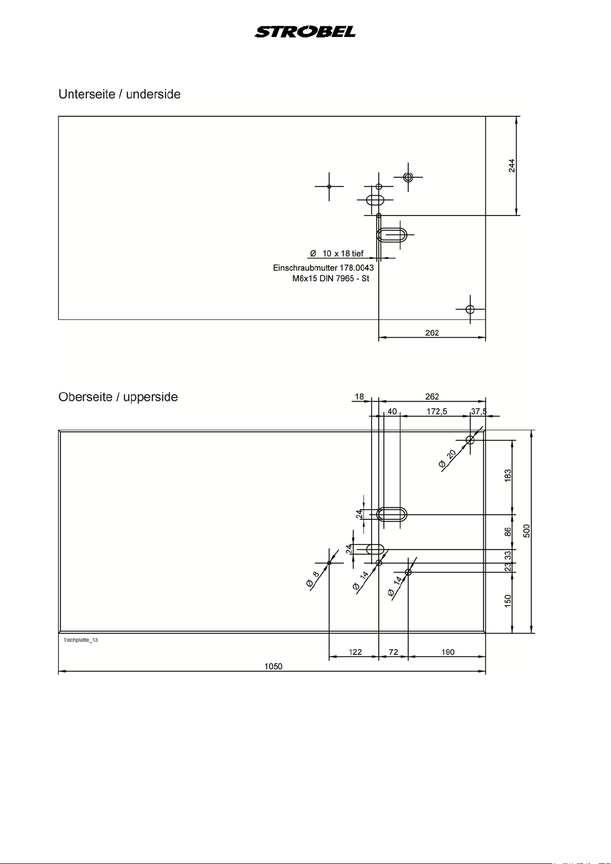
The upper part of the table plate must be provided with bores according to the
drawing.
Frame and pedals as well as electrical connections must be mounted according
to the printed circuit.
Screw on the motor. The electric connection must be carried out according to
the printed circuit in the enclosed operating instructions for the motor.
Screw the upper part to the table plate. (Fig. 2)
The bolts (1) and the pressure spring (2) are enclosed with the machine
accessories and must be fitted as shown in Fig. 2.
The pedal rod system must be suspended according to Fig. 1.
Push on the knee lever and secure with knurled screw.
(Not necessary with pneumatic venting)
9 BA_310D-R_3100D-R_A16-3_180117_en
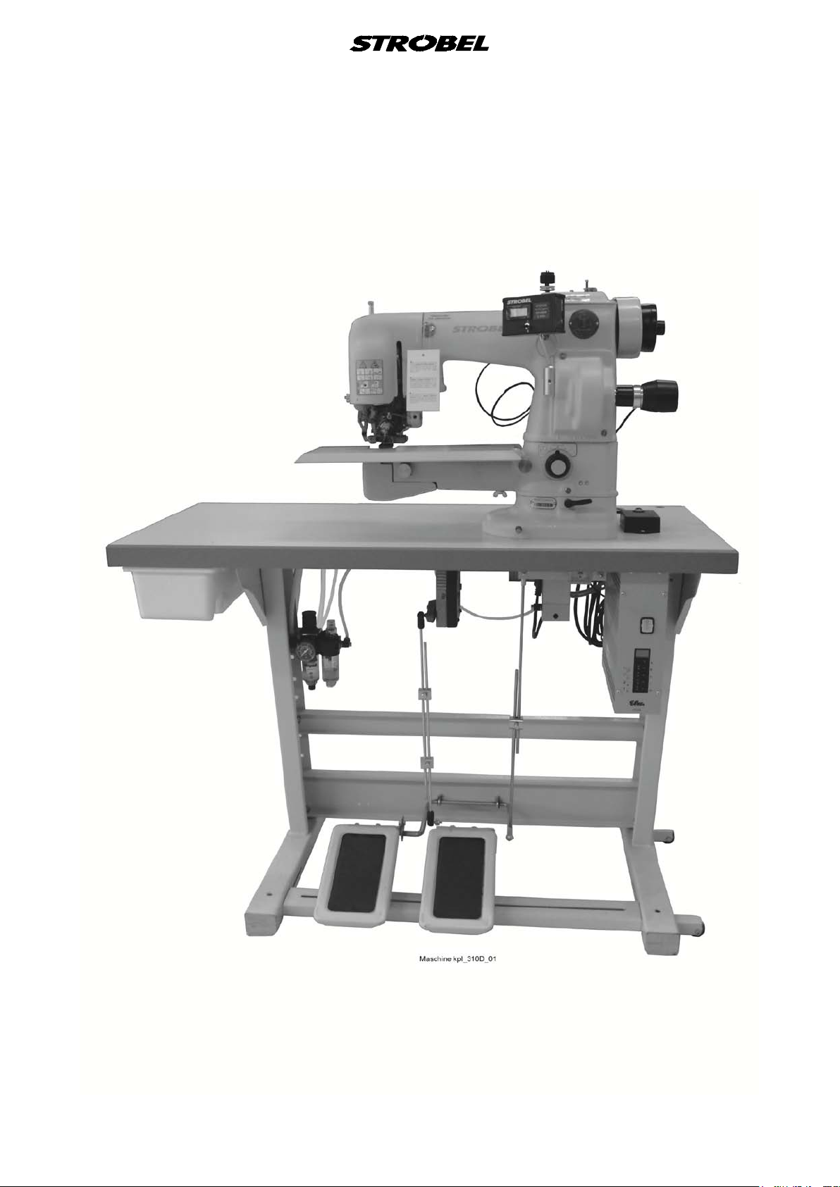
Fig. 1
Class 310D-R
10 BA_310D-R_3100D-R_A16-3_180117_en

Class 3100D-R
11 BA_310D-R_3100D-R_A16-3_180117_en

The cotton stand is mounted at the back on the right on the table plate after
assembly of the individual parts. (Fig. 1)
Check all screws at the frame for tight fit and retighten if necessary.
Mount the position transmitter and adjust corresponding to point “3.4.2
Positions of the machine“.
ATTENTION!
Prior to commissioning the machine it must be checked
whether the electric connection data on the type plate of the
motor, especially the network voltage and the frequency,
are according to the data of your current network.
All rust prevention agents, such as Vaseline or similar, must be carefully
removed from the sewing tools prior to commissioning the machine.
Fig. 2
12 BA_310D-R_3100D-R_A16-3_180117_en

3.3 Sense of rotation (Fig. 3)
The correct sense of rotation of the hand wheel is clockwise when looking at it
from the front.
Fig. 3
3.4 Motor drive via t oot he d be lt
3.4.1 Tension of the toothed bel t ( Fig. 4)
CAUTION! Danger of injury!
To check the tension of the toothed belt, switch off the
machine electrically, pull the mains plug and ensure the
machine has actually stopped by pressing the motor pedal.
The machine must not be operated without a belt guard for
the motor.
The tension of the toothed belt should not be too great. Slight thumb pressure
should be able to push the belt through by approx. 5 mm.
A too little or too great toothed belt tension can deteriorate the positioning of the
machine and therefore impair the function sequence.
Tensioning the toothed belt (Fig. 4):
a) Release upper and lower retaining screw (1), (2) at the machine upper
part.
b) Pull out the motor slightly and tighten the lower retaining screw (2) slightly.
c) Tension the toothed belt by swivelling the motor.
d) Retighten the upper and lower retaining screw (1), (2).
13 BA_310D-R_3100D-R_A16-3_180117_en

Fig. 4
3.4.2 Positions of the ma c hine
CAUTION! Danger of injury!
Danger of pulling in parts of clothing and of hair and danger
of crushing fingers and stitching fingers with needles!
When checking positions with switched-on machine keep
fingers and hands away from moving parts.
Machine with or without pneumatic:
The machine requires a needle position and depending on the sewing drive,
possibly also a reference position.
Reference position:
The reference position must be set in such a way, that the point of the
needle in direction of the insertion stitch closes with the right (inner) edge
of the needle slide plate.
Needle position (with stop in and outside the seam:
The needle position needs to be set in such a way that when the machine
is at standstill and the lifting is open the tip of the needle points in the
direction of the right stitch and the plunger, feed dog, and presser plate
are at one level (the position is located at about 8 mm after the upper
needle turning point).
Notes for sewing drives which have two needle positions:
The needle position mentioned above is position 2 at the sewing drive.
The position 1 at the sewing drive should be set in such a way that when
the machine is at standstill the tip of the needle stands about
3 mm in the direction of the left stitch after the lower needle turning point.
14 BA_310D-R_3100D-R_A16-3_180117_en

3.5 Intermediat e venting (Fig. 5)
If an intermediate venting with the knee lever should become necessary with
attached pneumatic venting, it can be mounted on the screw (1) in its usual
position.
Fig. 5
15 BA_310D-R_3100D-R_A16-3_180117_en

4 Notes on usage
for using different needle types.
4.1 Needles and threads
By selecting the most suitable needles and threads for the relevant sewing
material one can influence the sewing quality decisively.
Only tested GROZ-BECKERT needle system 1828 E should be used.
The machine is supplied with needles of thickness 80.
Note: An intact needle is of decisive importance for a good initial stitch.
Bent needle points, which can in part only be visible under a
magnifying glass, impair the sewing result.
Therefore, exchange your needles in good time!
We recommend endless twined polyester threads with a thickness of 120/2.
They are to be preferred to a spun thread, due to their high strength and good
sliding ability at low thread volume.
Guaranteed remark!
This machine has been set and sewn off with genuine
GROZ-BECKERT needles.
No guarantee can be granted if the settings are modified
4.2 Inserting the nee dle (Fig. 6)
CAUTION! Danger of Injury!
Switch off the machine before changing the needle and
ensure the machine is off by pressing the pedal for
switching the motor. Otherwise there is a danger of injury
Due to the bent shape of the needle the position in the needle lever is given.
Care must only be taken that the needle piston is pushed in the slot of the
needle lever up to the stop and that the needle clamping plate (6) is tightened
with the screw (5).
through crushing and needle stitches.
16 BA_310D-R_3100D-R_A16-3_180117_en
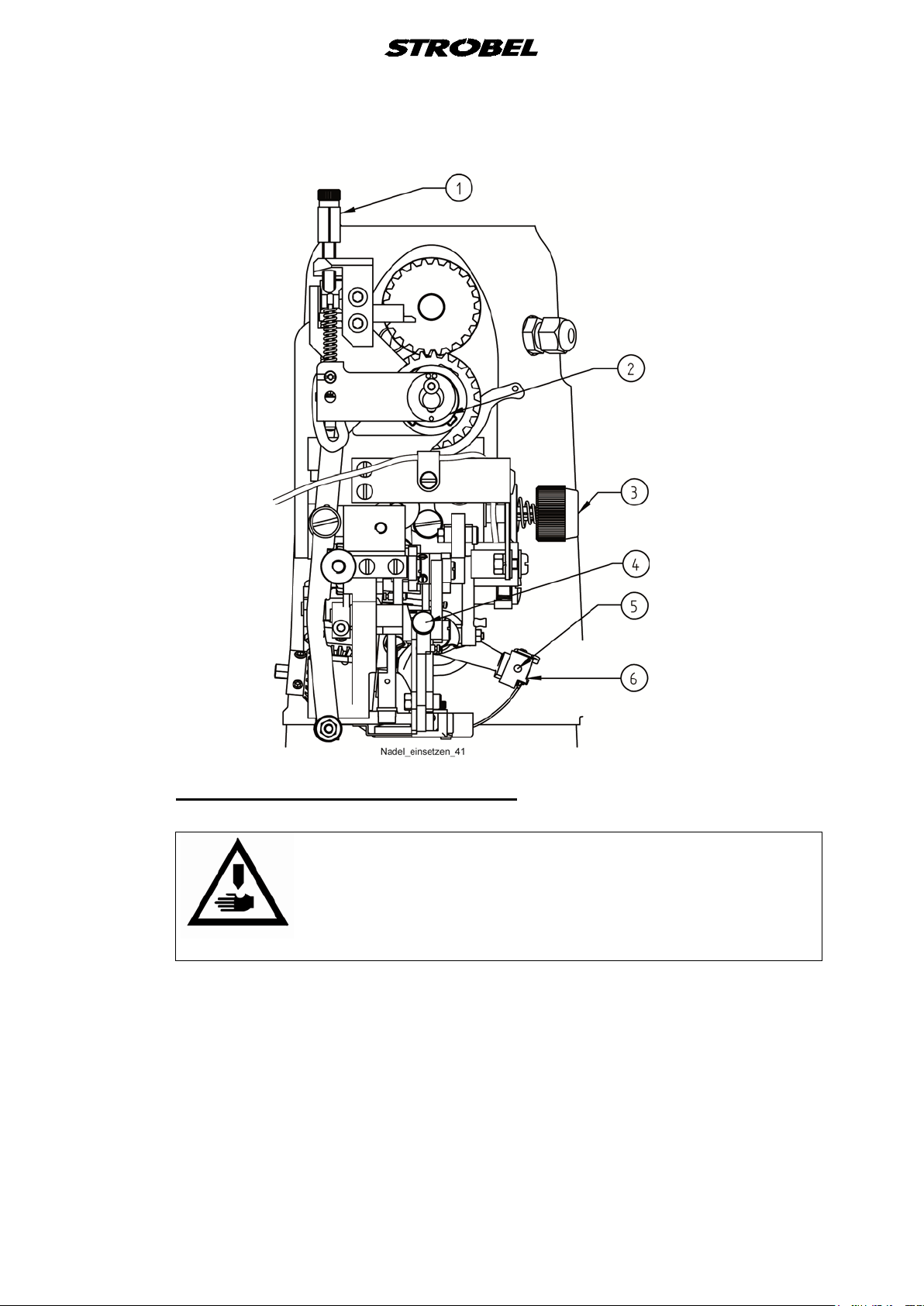
Fig. 6
4.3 Threading and thread run (Fig. 7)
CAUTION! Danger of injury!
Switch off the machine prior to threading and ensure the
machine is off by pressing the pedal for switching the
motor.
Fig. 7 shows the correct threading by using the thread sensor.
17 BA_310D-R_3100D-R_A16-3_180117_en

Fig. 7
18 BA_310D-R_3100D-R_A16-3_180117_en

4.4 Winding up the thread (Fig. 8)
The course of the thread during winding up is shown in Fig. 8.
Care must be taken that not too much of the thread is wound onto the reel and
that the reel walls are not pushed apart, faulty reels must immediately be
replaced with new ones.
Fig. 8
4.4.1 Installing the bobbin and threading the bobbin thread (Fig. 9)
By turning the needle lever to its highest position with the hand wheel, the
bobbin (1) can be taken out and reinserted. Fold the bobbin holder flap away
from the bobbin capsule with a short jerk, the bobbin then jumps by spring
pressure out of the bobbin capsule so that it can be easily removed.
When inserting the bobbin take care that the bobbin thread unwinds from the
underside of the bobbin. Then guide the start of the bobbin thread through the
slot at the right hand side of the bobbin capsule and hold it lightly at the stitch
plate.
Then turn the hand wheel of the machine a full rotation and at the same time
hold the needle thread lightly tensioned after take up by the hook point. This
pulls the bobbin thread correctly under the leaf spring.
It is best to then lightly twist together the needle thread and the bobbin thread
and pull them together to the back through the stitch plate hole.
19 BA_310D-R_3100D-R_A16-3_180117_en

Fig. 9
4.5 Thread tensioning (Fig. 6)
Dependent on grade, characteristic and thickness of the thread as well as the
sewing material, the thread tensioning is adjusted to the required seam diagram
with the tensioning nut (3).
4.5.1 Thread tightening spring – needle thread (Fig. 10)
The tension of the rotary spring (1) can be modified after releasing the grub
screw (2) and by turning at the headed bolt (3). It starts to tension the thread
when the thread loop is approx. 15° in front of the upper point of the hook, that
is, before it can fall off to the right of the hook.
Fig. 10
20 BA_310D-R_3100D-R_A16-3_180117_en

4.5.2 Thread tensioning – r eel thread (Fig. 11)
The leaf spring (2) regulates the bobbin thread tension. By turning the flat-head
screw with catch (1), the leaf spring must be adjusted in such a way that when
the bobbin is inserted, and the thread is correctly pulled under the leaf spring
and the bobbin case is released, the latter, together with the bobbin drops
slowly down. A slight pull on the thread might be necessary.
Fig. 11
4.6 Adjusting the stitch length ( Fig. 8 and Fig. 12)
CAUTION! Danger of Injury!
Switch off the machine and ensure it is switched off by
pressing the pedal for switching the motor.
Otherwise there is a danger of injury through crushing and
The stitch length can be adjusted after lifting the cover (1) (Fig. 8).
First release grub screw (1) (Fig. 12), then turn cheese-head screw (2) (Fig. 12)
to the left, the stitch length becomes larger, or to the right, the stitch length
becomes smaller.
After adjusting the required stitch lengths, retighten the grub screw (1) (Fig. 12).
needle stitches.
21 BA_310D-R_3100D-R_A16-3_180117_en

Fig. 12
4.6.1 Adjusting the upper feed path (Fig. 6)
By activating the right pedal the upper feed path is enlarged, that is, multi-width
can be worked in.
By turning the knurled screw (1) to the left, multi-width can be worked in
continuously.
Depending on whether you work with short or long stitch length, the position on
eccentric bush (2) = 2-5 mm stitch length or
position = 4 - 7 mm stitch length can be adjusted.
22 BA_310D-R_3100D-R_A16-3_180117_en

4.7 Stitch depth
By stitch depth one understand the distance of the highest plunger position to
the outside radius of the needle, the plunger presses the sewing material from
underneath in the stitch plate opening, so that the needle stitches into the fabric
layers at the required depth.
Low stitch depth: the needle penetrates less deep into the fabric layers
of the sewing material.
Large stitch depth: the needle penetrates deeper into the fabric layers of
the sewing material.
With too low or too large a stitch depth, omissions or through-stitches can
occur.
4.7.1 Adjusting the stitch depth (Fig. 2 and Fig. 6)
With the aid of the stitch depth regulating button (3) (Fig. 2) on the lower arm on
the right, the plunger can be lifted or lowered dependant on the thickness of the
fabric. Above this regulation button is a plate which shows how the button must
be turned so that the plunger is lowered or lifted.
Turning the button to the right – plunger goes upward,
needle penetrates deeper.
Turning the button to the left – plunger goes downward,
needle penetrates less deep
See also “4.7.2 Digital stitch depth display (Fig. 13)”.
The stitch depth for the side plunger is adjusted with the knurled screw (4)
(Fig. 6) on the left above the stitch plate.
Turning to the front (clockwise) – needle penetrates deeper
Turning to the back (anti-clockwise) – needle penetrates less deep.
23 BA_310D-R_3100D-R_A16-3_180117_en

4.7.2 Digital stit c h de pt h display (Fig. 13)
The plunger height can be read off digitally from the stitch depth display. This
makes finding earlier adjustments substantially easier by frequently changing
sewing material thickness.
The current supply is via a 9 V battery in the housing. To prevent premature
discharging of the battery, the display should be switched off with the toggle
switch at the housing during longer work breaks and when finishing work.
Always valid: Small number - thin sewing material
Large number - thick sewing material
The adjustment of the stitch depth by one digit (= 1 point of the display unit) is
equal to a plunger height modification of 0.01 mm.
When turning the regulating button to the right to the stop a value between 003
and 006 appears on the display.
Fig. 13
4.7.3 Changing the battery (Fig. 13)
a) Bring the switch to 0 position.
b) Open cover on the backside of the housing
c) Change the battery - ATTENTION! Observe the polarity!
d) Close cover.
24 BA_310D-R_3100D-R_A16-3_180117_en

4.8 Plunger stop
danger of injury, especially a danger of crushing fingers due
Frequently it is necessary when trimming fabric to sew over different fabric
thicknesses at the same work piece, whereby the penetration depth of the
needle, viewed from the upper side of the sewing material, must always remain
the same.
The plunger built- into our machines carries out this work automatically in
cooperation with an adjustable plunger stop mounted on the stitch plate.
(This is not true for all machines or stitch plates.)
4.8.1 Adjusting the plunger stop (Fig. 14)
CAUTION! Danger of Injury!
When adjusting in the area of the stitch plate there is
to accidental activation of the pedals!
First set the plunger with the stitch depth regulation button so high that the
required thickness of the sewing material, in most cases the outside fabric, is
stitched blind satisfactory.
Then the plunger stop supported on the stitch plate is adjusted with the knurled
screw (partly also hexagon nut) in such a way, that the sewing material is
pressed from above onto the plunger.
Now the plunger, under pressure from a spring, can rise above several layers of
fabric, cross seams, thickenings etc lying above each other only to such a
height, that the upper fabric layers and not the outside fabric is stitched.
The above adjustment requires some technical knowledge and experience.
Care must be taken that the pressure spring (1) is only adjusted as much as is
necessary for the correct effect of the plunger stop. This keeps the pressure of
the plunger onto the plunger stop as low as possible and less stress is put on
stitch plate and machine.
With adjustment of the plunger pressure at the works, the screw for the plunger
regulation (2) is flush with the plunger guide (4).
By turning the plunger adjusting screw (3), including the screw for the plunger
regulation (2), to the right it increases, to the left it decreases.
25 BA_310D-R_3100D-R_A16-3_180117_en

Fig. 14
4.9 Interval gear
The interval 1:2 or 1:3 guarantees an elastic seam almost free of marking with
extremely difficult to work fabric qualities.
The principle of the interval is based on the repeat of a different plunger height,
which always remains the same with the individual penetrations of the needle.
We use it with two different machine types:
a) Needle lever with radial movement.
The needle stitches the outside or upper fabric with each second (1:2) or
third (1:3) rotation of the machine. With the other rotations the penetration
is carried out only in the upper fabric layers.
b) Needle lever with radial and pendulum movement.
The interval 1:2 enables the needle in each case to make a right (in the
upper fabric) and a left (in the inside lining) penetration
The difference of the plunger height between the individual stitches is partly
fixed set or stepless adjustable from 0 to + (=maximum approx. 0.2 mm).
26 BA_310D-R_3100D-R_A16-3_180117_en

4.10 Seam lock
Attention!
Switch off machine electrically!
Attention!
Danger of finger bruises in the area of pneumatically
operated parts.
4.10.1 General
The sewing cycle begins with the point tack by pressing the pedal forwards.
The sewing speed is independent of the pedal. After completing the point tack,
the machine sews at the speed set by the pedal. When the pedal is released at
the end of the stitch, the seam lock becomes active and the machine lifts off
automatically after finishing the point tack. An intermediate lift thus only
functions using the knee lever.
The point tack function is always switched on by default. The function can be
generally switched off by the software or temporarily by the switch (S2) to the
right of the head.
During seam lock, the lower feed dog and side feed dog are deactivated and an
additional thread tension is active. This thread tension needs to be set
separately. (Fig. 7)
The start and end backtack are active by default. As an alternative, you can use
only the end backtack.
4.11 Sewing drive
The machine is as a rule equipped with the sewing drive selected by you.
Please note the separately enclosed operating instructions for the sewing drive.
There you find notes and the instructions for programming the control including
the motor speed adjustments.
27 BA_310D-R_3100D-R_A16-3_180117_en

5 Operating the sewing machine
CAUTION! Danger of Injury!
Take sufficient care during sewing and observe the sewing
area!
Otherwise there is a danger of injury through crushing and
For machines with 2 pedals: push down the left pedal fully increases the top
feed length (multi-width take-up). With this configuration, motor control is taken
over by the right pedal.
To vent the machine, a pneumatic venting system can be supplied instead of
the knee lever.
When releasing the pedal to switch on the motor, the machine moves to its
position and pneumatic venting takes place.
needle through-stitches.
Pressing the pedal forwards closes the vent and the machine starts to sew.
Fig. 15
5.1 Switch-on
Switch on the main switch on the right underneath the table plate.
With pneumatic lifting, connect the service unit to the compressed air network
(10 bar) or connect the compressor and regulate to 5 – 6 bar.
The lifting is now opened and the sewing machine is ready for operation.
28 BA_310D-R_3100D-R_A16-3_180117_en

5.2 Inserting and re m ovi ng the sewing material
When during standstill of the machine the needle is approx. 15 mm after its
upper dead point in front of the right penetration, the presser plate and the
plunger can be moved downwards by activating the knee lever. At the same
time the needle thread tension is vented.
For pneumatic venting also see point “0 The machine is as a rule equipped with
the sewing drive selected by you.
Please note the separately enclosed operating instructions for the sewing drive.
There you find notes and the instructions for programming the control including
the motor speed adjustments.
Operating the sewing machine”.
Now the sewing material can be inserted into the machine between stitch plate
and presser plate.
The sewing material cannot be removed until the last stitch has been
completely carried out, the needle thread loop has dropped from the hook, the
needle is again in the position mentioned above and the knee lever is activated.
When using a sewing drive with needle height position, the positioning is
carried out automatically.
ATTENTION! Do not let the machine run if there is no fabric between stitch
5.3 Sewing
The lining (with cl. 310D-R) or the fabric hem (with cl. 3100D-R half lined
working) will be inserted in the left stitch plate opening standing up.
In both cases it is advantageous to tack or to peg with hairpins.
Cl. 310D-R short machine arm
When hemming the lining the jacket lies to the left.
Cl. 3100D-R long machine arm
When hemming the fabric the jacket lies to the right.
By exchanging the enclosed accessories the work sequences can be
exchanged.
In connection with this please observe point 7 Variable sewing tools.
plate and feed dog.
29 BA_310D-R_3100D-R_A16-3_180117_en

5.3.1 Hemming w ith blind stitch
If there are no experience values available, the best thing to do is to carry out
the following settings in sequence:
a) Adjust required stitch length
b) Adjust stitch depth
c) Check plunger stop and if necessary adjust
d) Adjust material guide (if available)
e) Check presser plate lift. (Mechanic's instructions)
f) Check stitch length.
g) Adjust thread tension, the seam should lie loose on the hem as a rule.
h) Correct the seam diagram.
Insert the sewing material and take care that the start of the hem can be
taken up by the feed dog after the first stitch.
Check the sewing result achieved and possibly modify the adjustments
carried out above.
With through stitches or omissions at the outside fabric (right hand initial
stitch) or the hem edge or the lining (left hand initial stitch), adjust the
stitch depth settings.
„Markings“ caused by the penetration of the needle in the outside fabric
(shift of fibres) sometimes cannot be avoided with extremely thin und hard
sewing material.
When sewing take care that the hem edge always runs along the material
guide (if available). Jerky activation of the pedal should be avoided, as
changes in speed during the sewing process can under certain
circumstances have a negative effect on the initial stitch.
NOTE: To avoid having a build-up with thick fabrics it is recommend to
cut off the corners at the cross seams prior to hemming.
30 BA_310D-R_3100D-R_A16-3_180117_en

5.4 Problems during s e wing and troubleshooting
CAUTION! Danger of Injury!
Switch off the machine and ensure it is switched off by
pressing the pedal for switching the motor.
Otherwise there is a danger of injury through crushing and
needle stitches.
• Thread breaking
Possible causes:
- sharp edges or grooves in needle guide, take-up lever, shuttle or
needle eye when the machine has been used for a long time.
- The thread between shuttle and bobbin case breaks or is pinched off.
- Too much oil has penetrated the shuttle path
- The bobbin is packed too tight or the bobbin sides are forced apart
because the thread is too tightly wound.
- Bobbin case vent or shuttle bridge are not correctly adjusted.
- The shuttle to needle or needle rise has not been correctly adjusted or
has become displaced, meaning that the thread loop is not always
taken up.
- Thread tension is set too slack or too tight.
Remedy:
- Replace or re-polish the damaged parts
- Dismantle shuttle, remove bobbin case and polish the feed edges of
the bobbin case and shuttle path.
- Using an absorbent thread (cotton thread, core spun thread), sew out
on a remnant.
- Insert new bobbin
- Slowly turn the machine by hand and check whether the loop slides
unimpeded through the shuttle. If not, readjust bobbin case vent or
shuttle bridge.
- Correct shuttle position or loop lift.
- Correct thread tension - check thread line.
ATTENTION! thread course, thread, needle plate with plunger and cloth
retainer, needle and thread tension should always be set
and chosen according to the material to be sewn.
31 BA_310D-R_3100D-R_A16-3_180117_en

• Uneven stitching
Possible causes:
- frequently worn or damaged needles
- height of needle plate or needle slide plate incorrectly adjusted
- unsuitable needle thickness (too thin)
Remedy:
- Replace damaged needle. Check adjustments and correct if
necessary. Use correct needle thickness.
• Missing loops
Possible causes:
- incorrectly adjusted or badly adjusted shuttle
- loop lift too small
Remedy:
- Turn machine by hand and check shuttle motion. The cause can
usually be seen.
- If necessary, also correct thread tension or thread tension spring.
- correct loop lift.
• Loops become stuck
Possible causes:
- thread tension too slack
- needle not tacking
Remedy:
- Check thread tension or thread tension spring
- Check stitch depth (even for skip stitch or plunger lowering)
• Machine does not start
Possible causes:
- Control fault
- Mechanical damage
Remedy:
- Switch machine off and on again
- Rectify mechanical faults
- Check programming. If necessary, call customer service.
32 BA_310D-R_3100D-R_A16-3_180117_en

• The sewing resul t doe s not come up to your expectations
Possible causes:
- Damaged sewing tools or wear caused by improper use or natural
wear following long use of machine.
- The machine has become mechanically misadjusted
- Unsuitable needle thickness (see “4.1 Needles and threads”)
- Unsuitable sewing thread (see “4.1 Needles and threads”).
Remedy:
- Replace damaged parts - customer service
- Work carried out by engineers: see also mechanic’s instructions and if
necessary, call customer service
- Replace needle; also check needle tip for damage.
• Marks on or damage to the sewn item
Possible causes:
- unsuitable feed gearing
- Sewing tools incorrectly set
- Damaged sewing tools
- Unsuitable needle or thread thickness.
Remedy:
- check settings
- check feed (gearing), if necessary, replace feed
- choose needle and thread to suit sewing material.
• Difficulties during feeding the sewn material (stitch length)
Possible causes:
- Feed incorrectly adjusted
- Unsuitable feed gearing
- Incorrect presser plate take-up
- Bunching of the sewn item on the needle plate, particularly when
cross-seaming.
Remedy:
- check settings, if necessary change feed.
- Check lower side of needle plate, feed and sewing tools for damage, if
necessary replace or re-polish.
- The suitable stitch plate must be selected for thick sewn material –
see “7 Variable sewing tools” and “8 Optional Extras”.
33 BA_310D-R_3100D-R_A16-3_180117_en

5.5 Incorrect stitches (Fig. 16)
The correct two-thread blind stitch is shown in Fig. 16.
Incorrect stitches can occur if the needle does not take up the sewing material
or does not carry out initial stitch or the hook does not take up the thread loop.
Fig. 16
34 BA_310D-R_3100D-R_A16-3_180117_en

6 Machine maintenance
CAUTION! Danger of Injury!
Disconnect the machine from the mains and ensure that it
is off by pressing the pedal for switching the motor.
Otherwise there is a danger of injury through crushing and
The machine must be oiled daily at the points marked red (oil bottle is included
with the machine accessories). For this remove the housing cover on the right
top, the under arm cover bottom left and the head hood.
Fabric fibres and dirt which collect at the movable parts of the machine must be
removed, as they could cause errors and impair the operating safety.
The hook path should also be oiled from time to time with a drop of oil, there is
a bore for this in the hook cover.
needle stitches.
35 BA_310D-R_3100D-R_A16-3_180117_en

7 Variable sewing tools
CAUTION! Danger of Injury!
Disconnect the machine from the mains and ensure that it
is off by pressing the pedal for switching the motor.
Otherwise there is a danger of injury through crushing and
needle stitches.
The following table shows the available sewing tools.
36 BA_310D-R_3100D-R_A16-3_180117_en

Cl. 310D-R
Standard
8,0 mm Opening
Optional
7,0 mm Opening
Standard
Optional
250g to 700g
Fabric and lining hems
under 300g
Fabric and lining hems
Standard
Optional
Standard
Optional
Needle plate
Plunger
Pressure spring
280.0265
281.0131
Standard
161.0157
280.0266
281.0125
Fabric qualitiy
Stitch formation
Feed dog
182.0140
182.0318
8 mm
(or 6 mm or 4 mm)
under the hem edge
182.0131
282.0320
37 BA_310D-R_3100D-R_A16-3_180117_en

Cl. 310D-R
Optional
Optional
at 500g
only lining hems
Optional
182.0131
Needle plate
280.0267
10,0 mm Opening
281.0126
Plunger
Pressure spring
Fabric qualitiy
Stitch formation
Optional
161.0047
8 mm
(or 6 mm or 4 mm)
under the hem edge
38 BA_310D-R_3100D-R_A16-3_180117_en
Feed dog
282.0320

Cl. 3100D-R
Standard
8,0 mm Opening
Optional
7,0 mm Opening
Standard
Optional
250g to 700g
Fabric and lining hems
under 300g
Fabric and lining hems
Standard
Optional
Standard
Optional
Needle plate
Plunger
Pressure spring
380.0265
281.0131
Standard
161.0157
380.0266
281.0125
Fabric qualitiy
Stitch formation
Feed dog
182.0140
182.0319
8 mm
(or 6 mm or 4 mm)
under the hem edge
182.0131
282.0320
39 BA_310D-R_3100D-R_A16-3_180117_en

Cl. 3100D-R
Optional
Optional
at 500g
only lining hems
Optional
182.0131
Needle plate
280.0267
10,0 mm Opening
281.0126
Plunger
Pressure spring
Fabric qualitiy
Stitch formation
Optional
161.0047
8 mm
(or 6 mm or 4 mm)
under the hem edge
40 BA_310D-R_3100D-R_A16-3_180117_en
Feed dog
282.0320

8 Optional Extras
The following equipment is additionally available for the machine and can be
ordered from the works with the machine or as attachment:
8.1 Plunger
181.0070 Side plunger, round shape
(for delicate lining)
8.2 Additional parts for hemm ing half lined jack e t s
386.0347 Additional parts for hemming half lined jackets
(for cl. 31OD only - for all needle plates)
incl.
174.0204 Flat head screw
182.0319 Feed dog
183.0136 Presser foot
186.0347 Height adjustment (4 mm under the hem edge)
186.0348 Height adjustment (6 mm under the hem edge)
41 BA_310D-R_3100D-R_A16-3_180117_en


Und wir können noch mehr für Sie tun!
Unser Lieferprogramm bietet für jede Branche und
jegliche Anforderung genau die richtige Problemlösung.
And we can do a lot more for you!
Our range offers the correct problem solution for
every branch and for all requirements.
Für die Bekleidungsindustrie:
Ein- und ZweifadenHochleistungs-Saummaschinen
DoppelblindstichSaummaschinen
Zweifaden-BlindstichStafermaschinen
Roll- und Flachpikiermaschinen
Pikier-Automat
und
weitere Spezial-Nähmaschinen
For the clothing
industry:
Single and two thread high
performance hemming
machines
Bluff edge hemming machines
Two thread blind stitch felling
machines
Roll and at padding machines
Automatic lapel padding
machine
Für die Schuhverarbeitung:
Einfaden-Überwendlichmaschinen mit und ohne
Differentialtransport
For the shoe industry:
Single-thread overseaming machines with and without differential feed
Für Kürschnereien
und Pelzkonfektion:
Pelzschnellnäher
For the fur industry:
High-speed fur sewing machines
Für Heimtextilien:
Ein- und ZweifadenBlindstichmaschinen
For the home textiles
industry:
Single and two thread
blind stitch machines
Für die Polsterverarbeitung:
Ein- und ZweifadenÜberwendlichmaschinen
Ein- und ZweifadenBlindstichmaschinen
For the upholstery
industry:
Single and two thread
overseaming machines
Single and two thread
blind stitch machines
Für die Konfektion
technischer Textilien:
Ein- und ZweifadenÜberwendlichmaschinen
For the processing
of technical textiles:
Single and two thread
overseaming machines
and other special sewing
machines

Noch Fragen?
Dann rufen Sie uns an, schreiben Sie uns oder
kommen Sie einfach bei uns vorbei.
Sie können jederzeit weitere Informationen über
unsere Produkte anfodern oder die StrobelNähmaschinen in unserem Ausstellungsraum live
erleben. Wir freuen uns auf Sie!
Any further questions?
Then phone, write or simply come and see us. You
can have further information about our products at
any time, or experience the Strobel machines live in
our show room. We’re looking forward to meeting you!
Sp ez ia l ma sc hi ne n G mb H
Postfach 1242
82168 Puchheim
Siemensstraße 3
82178 Puchheim
DEUTSCHLAND
www.strobel.biz
Telefon: +49 89 80096-0
Telefax: +49 89 80096-190
 Loading...