


For the professional user
Mechanic‘s Instructions
Für den professionellen Anwender
Mechanikeranleitung
Class:
Klasse:
Model:
Ausführung:
Dated:
Stand:
218D-TP-R
4
Spezialmaschinen GmbH

The sign of quality
ou nd the Strobel trademark on every Strobel
Y
machine leaving our works. And with good reason.
This symbol is a guarantee of the high quality of
our products. Quality which creates trust – trust
in our technology, our service and, not least of all,
in our good name.
Im Zeichen der Qualität
ie nden die Strobel-Schutzmarke auf jeder
S
Strobel-Maschine, die unser Werk verlässt.
Und das aus gutem Grund. Denn dieses Zeichen
garantiert Ihnen die hohe Qualität unserer
Produkte. Qualität, die Vertrauen schafft – in unsere
Technik, unseren Service und nicht zuletzt in unseren
guten Namen.

A decision with future
trobel clients know that they can expect a particularly
S
high standard of performance from our company and our
machines. Now you have settled for one of our products.
For us this is a source of encouragement and of obligation
to Justify your trust.
If you wish to prot from the performance and efciency of
your Strobel machine as long as possible, exact handling
and thorough care is necessary. For this reason we kindly
request that you read the operating instructions closely.
It provides all the information you need for trouble free
operation.
And if you do happen to need a spare part the enclosed
spare parts list gives a complete overview. It is clearly
classied according to components so that you can nd the
required part quickly and easily. In order to avoid errors we
request you to quote machine class, machine number and
part number completely on your spare part order.
We wish you lots of success in your work with your new
Strobel machine.
Spezialmaschinen GmbH


Mechanic's instructions
STROBEL Class 218D-TP-R
Contents
1 General notes on safety ............................................................................................ 5
2 General ..................................................................................................................... 7
2.1 Operating instructions ..................................................................................... 7
2.2 Class description, machine number and reference position left/right ............. 7
2.3 Machine applications ...................................................................................... 7
2.4 Technical data ................................................................................................ 8
2.5 Brief setting instruction ................................................................................... 9
3 Hints for repair and settings .................................................................................... 10
3.1 Mounting the needle plate ............................................................................ 10
3.1.1 Removing the needle plate (Fig. 1) .................................................. 10
3.1.2 Remounting the needle plate ........................................................... 11
3.1.3 Setting the needle plate (Fig. 1) ....................................................... 11
3.1.4 Adjusting the needle ........................................................................ 12
3.1.5 Replacing the needle slide plate (Fig. 2) .......................................... 12
3.2 Needle lever ................................................................................................. 13
3.2.1 Setting the needle lever path (Fig. 1) ............................................... 13
3.2.2 Lateral adjustment of the needle lever (Fig. 1) ................................. 13
3.3 Stroke of loop ............................................................................................... 14
3.3.1 Setting the needle stroke (Fig. 3) ..................................................... 14
3.4 Looper .......................................................................................................... 15
3.4.1 Removing and re-mounting the looper (Fig. 3 + Fig. 4) .................... 15
3.4.2 Setting the shuttle in relation to the needle (Fig. 5) .......................... 16
3.4.3 Removing and fitting the bobbin case (Fig. 5) .................................. 16
3.4.4 Thread tension - bobbin thread (Fig. 7) ............................................ 17
3.4.5 Setting the bobbin case venting (Fig. 4) ........................................... 17
3.5 Feed motion .................................................................................................. 18
3.5.1 Feed (bottom feed) (Fig. 9) .............................................................. 18
3.5.2 Setting the feed motion (Fig. 8) ........................................................ 18
3.6 Presser plate ................................................................................................ 19
3.6.1 Setting the presser plate (Fig. 9) ...................................................... 19
1 MA_218D-TP-R_A4_181015_en

3.7 Plunger ......................................................................................................... 20
3.7.1 Removing the plunger (Fig. 10) ........................................................ 20
3.7.2 Fitting the plunger (Fig. 10) .............................................................. 21
3.7.3 Adjusting plunger motion (Fig. 11) ................................................... 21
3.7.4 Adjusting the digital stitch depth (Fig. 12) ........................................ 22
3.8 Setting the plunger lowering (Fig. 13, Fig. 14, Fig. 15) ................................. 23
3.9 Thread spreader ........................................................................................... 26
3.9.1 Setting the thread spreader (Fig. 16) ............................................... 26
3.10 Seam lock ..................................................................................................... 27
3.10.1 General (Fig. 17) .............................................................................. 27
3.11 Pneumatic venting ........................................................................................ 28
3.11.1 General ............................................................................................ 28
3.11.2 Setting the lifting .............................................................................. 28
3.12 Sewing drive ................................................................................................. 28
2 MA_218D-TP-R_A4_181015_en

Appendix
Circuit diagrams
Electric mains, sewing drive - sewing machine lamp:
258.00.35 Mains connection plan cl. general
(AB611A with/without sewing machine lamp gen.)
Connecting the sewing ma chine:
258.21.66 Electrical connection plan cl. 200, 300
258.10.16 Electrical wiring diagram – Plunger lowering
Cl. 218D-TP as of version 3 and Cl. 325-40D-TP as of version 9
259.00.62 Pneumatic circuit diagram cl. 218D-TP-R
259.10.62 Pneumatic construction circuit diagram cl. 218D-TP-R
Connecting Plunger lowe r ing and spot tack:
258.10.25 Electric circuit diagram cl. 218D-TP-R
Connecting digital display:
258.21.24 Electric connection diagram
Subject to change without prior notice
3 MA_218D-TP-R_A4_181015_en

4 MA_218D-TP-R_A4_181015_en

1
General notes on safety
Every person in charge of setting up, operating, servicing and repairing the
machine must first read and understand the operating instructions and
particularly the safety instructions before starting up the machine.
Failure to comply with the following safety instructions can lead to bodily
injury or damage to the machine.
1. The machine must only be operated by persons familiar with the relevant
operating instructions and who have been instructed accordingly.
2. Before commissioning also read the notes on safety and the operating
instructions of the sewing drive manufacturer.
3. Only use the machine in the intended manner and never without the
provided guards. Always observe the pertinent safety regulations.
4. Switch off the main switch or pull the power plug for threading, changing
the reels, exchanging sewing tools such as needle, gripper, needle plate,
transport devices, possibly cutter and cutting block, for cleaning and when
leaving the workplace as well as for maintenance.
5. General maintenance tasks may be carried out only by properly trained
persons in accordance with the operating instructions.
6. Repair work, retrofitting and maintenance may be carried out only by
technicians or specially trained personnel.
7. When servicing or repairing pneumatic equipment, the machine must be
disconnected from the pneumatic supply. Exceptions are only allowed for
adjustment work and tests of functionality performed by specially trained
technicians.
8. Only specially qualified technicians may work on the electrical equipment.
9. It is forbidden to work on electrically live components! Exemptions are
covered by the EN50110 (DIN VDE0105) regulations.
10. Any retrofitting or alterations to the machine may only be performed under
strict compliance with all pertinent safety regulations.
11. Only use our approved spare parts when servicing and/or repairing the
machine.
12. It is forbidden to operate the sewing head until it is determined that the
entire sewing unit complies with EU provisions.
13. It is essential that you observe and follow these instructions as well as the
generally valid safety regulations.
5 MA_218D-TP-R_A4_181015_en

14. Warning instructions given in the operating instructions that pertain to
especially dangerous parts of the machine must be indicated at these
positions using a safety symbol.
Warning instructions given in the operating instructions that pertain to
special injury hazards for operating personnel or technicians must be
indicated at these positions using a safety symbol.
6 MA_218D-TP-R_A4_181015_en

2
2.1
2.2
2.3
General
Operating instructions
Any person involved in the installation, operation, maintenance and repair of
the machine must have read and understood the operating instructions and
mainly the safety instructions before starting the machine.
Class descript ion, machine number a nd reference posit ion left/right
For side-referenced descriptions (right, left), the operating side of the machine
is the starting base.
The class descriptions (type) are at the front, the machine and model number
(towards the hyphen) is located below the cover on the right side on the
housing.
Machine applications
Two thread felling machine for felling of the under collar at the neckring of
jackets and coats
7 MA_218D-TP-R_A4_181015_en

2.4
Technical data
Recommanded rated speed 1300 min-1
Motor power 550 W
Toothed belt pulley/machine z = 38
Toothed belt profile HTD 5M-9
Stitch length 2 - 6 mm
(depend on fabric)
Kind of stitch: two thread blindstitch lockstitch
Stitch type 314
Needle system GROZ-BECKERT 1717 VRUE
Needle size 90
Thread polyester continuous filament
Thread size 80
Air pressure 6 bar
Average air consumption 40 l/h
Foot print 0.6 m x 1.1 m
Noise:
Average noise level at a speed of
n = 1300 min-1: LpAm 74,5 dB(A)
Noise test according to DIN 45635-48-1 KL3
8 MA_218D-TP-R_A4_181015_en

2.5
Brief setting instruction
Theoretic needle radius 43.6 mm
Theoretic needle glide plate 43.59 -0.03 mm
Stroke of loop 2.8 mm
Distance from looper point to needles eye 1.8 ±0.2 mm
Highest position of plunger 2 mm before plunger center
in relation to needle
Plunger stops in relation to needle 2 m m after plunger center
Start of feed motion in case needle’s eye 5 mm at way back
of 6 mm feed length before plunger center
Length of feed motion 2 - 6 mm adjustable
Feed position, rear 0.3 mm distance to clamp plate
Feed plate lift 4 - 5 mm
Feed plate rises needle point 10 mm before plunger center
Distance of guide block in relation 2.5 ±0.5 mm
to plunger guide plate
Lifting between feed plate and stitch plate 14.5 mm machine must
rotate without difficulty
Number of spot tacks 2 – 4 stitches
9 MA_218D-TP-R_A4_181015_en

3
3.1
3.1.1
Hints for repai r and settings
Attention, danger!
Observe safety and operating instructions before realizing
any maintenance and repair works.
Failure to do so may result in heavy bodily injuries.
Mounting the needle plate
Attention!
Switch off machine electrically!
Needle plates are set at works and can be replaced easily as complete kit.
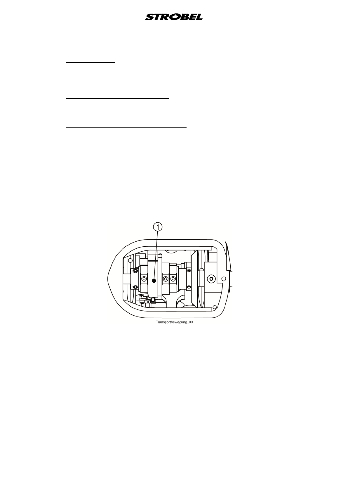
Removing the needle pla t e (Fig. 1)
1. Switch off the machine at the mains
For pneumatic venting: plunger, presser plate and feed are vented.
2. Remove needle.
3. Pull off lower arm cover.
4. Vent plunger, presser plate and feed using knee lever.
5. Push screw driver between lower arm and leaf spring.
6. Slacken bolt (5) and remove needle plate from machine.
10 MA_218D-TP-R_A4_181015_en

Fig. 1
3.1.2
3.1.3
Remounting the needle plate
Remount the needle plate in reversed order.
Setting the needle plate (Fig. 1)
The theoretical needle radius of 43.6 mm should be 0.01 - 0.04 mm smaller at
the needle slide plate; in other words, a checked needle is raised by
0.01 - 0.04 mm.
This is verified with a dial gauge.
If this setting is correct, there should automatically be a space of
0.25 - 0.35 mm between the needle and the needle plate radius (also verify with
a dial gauge).
Deviations from this will considerably detract from the sewing result and may, in
addition, result in damage or premature wear of the sewing tools.
By slackening the threaded pin (4) on the left and right in the head, and
slackening the fixing screws (5), the needle plate may be pushed carefully
upwards or down, towards the needle.
Warning! When tightening the screws, check that the needle plate is
horizontal.
11 MA_218D-TP-R_A4_181015_en

3.1.4
3.1.5
Adjusting the needle
Attention!
Switch off machine electrically!
The needle is adjusted in a lateral direction so that it is situated centrally in
relation to the needle plate (i.e. between the two screw holes).
Replacing the needle slide plate (Fig. 2)
The needle slide plate is attached to the top of the needle plate. It can be
removed by slackening the screw (1).
The channel of the needle of the needle slide plate should be centred on the
needle.
Fig. 2
12 MA_218D-TP-R_A4_181015_en

3.2
3.2.1
3.2.2
Needle lever
Attention!
Switch off machine electrically!
Setting the needle lever path (Fig. 1)
After removing the head cover and the thread tension adjustment button, the
needle lever must be turned down so far, that the eccentric bolt (1) can be
reached with a screw driver through the hole provided in the head. Once the nut
(6) has been slackened, the needle lever path is corrected by turning the bolt
(at the rear).
In this case, the distance between the shuttle point (for normal loop stroke and
position above the centre of the needle) and the end of the needle eye turned
towards it, must be 1.8 ±0.2 mm.
Lateral adjustment of the needle lever (Fig. 1)
The needle lever is set so that the needle is located centrally in relation to the
needle plate.
Adjustment can only be carried out by moving the bearing bushes (3) and (2) in
the head, to the side (by tapping gently).
(See also point “
3.1.4 Adjusting the needle”)
13 MA_218D-TP-R_A4_181015_en

3.3
3.3.1
Stroke of loop
Stroke of loop means the needle race from its lowest position to the spot where
the lower point is placed on top of the center of the needle.
Setting the needle stroke (Fig. 3)
Attention!
Switch off machine electrically!
Normally is a loop stroke of 2.8 mm. If it is necessary to change the loop stroke,
then slacken the two screws in the toothed wheel, (1) at the rear of the head
(Fig. 3). By turning this toothed wheel, the shuttle can be set so that it takes
hold of the thread loop earlier or later. When tightening the two screws, check
for normal play between the bevel wheels. If the loop stroke is altered, then the
needle lever almost always has to be readjusted.
Fig. 3
14 MA_218D-TP-R_A4_181015_en

3.4
3.4.1
Looper
Removing and re-mounting the looper (Fig. 3 + Fig. 4)
Attention!
Switch off machine electrically!
Dismantle the following parts:
Cover (rear of head), needle, needle plate, angle lever (2) (Fig. 4) with bolt (5)
and spring (1) (Fig. 4)and bevel wheel (2) (Fig. 3). The shuttle can now be
removed from the front.
Fitting in reverse order.
Ensure that the teeth of the bevel wheels marked red, (2) (Fig. 3) and (1)
(Fig. 3) and the surface of the shuttle shaft form one line again when
assembled.
Fig. 4
15 MA_218D-TP-R_A4_181015_en

3.4.2
Setting the shuttl e in relation to the nee dle (Fig. 5)
The gap between the shuttle tip and a 90 needle must max. 0.2 mm.
If it is necessary to adjust the shuttle, then this is done by slackening the
cylinder head screw (1) and turning the eccentric bushing (2).
Fig. 5
3.4.3
Removing and fitting the bobbin case (Fig. 5)
If a thread has become jammed between the bobbin case and shuttle, the
bobbin case must be removed, otherwise the machine will be slowed down.
This will entail removing the shuttle - see point “
mounting the looper (Fig. 3 + Fig. 4)”.
Once the screws (1) have been slacked, the shuttle cover (3) can be removed.
The bobbin case on the bobbin retaining flap (2) is then turned to position C
whereupon it is pulled out of the shuttle.
When replacing, ensure that the bobbin retaining flap (2) points in the direction
of the shuttle point (C).
3.4.1 Removing and re-
Fig. 6
16 MA_218D-TP-R_A4_181015_en

3.4.4
3.4.5
Thread tension - bobbin t hread (Fig. 7)
The leaf spring (2) regulates the bobbin thread tension.
By turning the flat-head screw with catch (1), the leaf spring must be adjusted in
such a way that when the bobbin is inserted, and the thread is correctly pulled
under the leaf spring and the bobbin case is released, the latter, together with
the bobbin, drops slowly down. A slight pull on the thread might be necessary.
Fig. 7
Setting the bobbin cas e venting (Fig. 4)
It must be possible to draw the loop of the needle thread, taken up by the
shuttle, easily and without resistance through the bobbin case.
Bobbin case venting must set in once the loop has left the uppermost point of
the bobbin case and must have vented it when the loop is drawn between the
bobbin case and the shuttle bridge nose.
The moment of bobbin case venting can be adjusted by slackening the right nut
(4) on the needle lever bearing and turning the stop lever (3).
Retighten nut.
17 MA_218D-TP-R_A4_181015_en
3.5
3.5.1
3.5.2
Feed motion
In order to achieve a starting stitch as even as possible, it is also important to
set an even, synchronous feed motion.
Feed (bottom feed) (Fig. 9)
The machine cl. 218D-TP-R is factory-fitted with a pyramid-teethed feed (3).
Setting the feed mot ion (Fig. 8)
The feed cam (1) on the main shaft must be set so that feed begins when the
eye of the needle is located 5 ±1 mm before centre of the plunger on its return
(after lower dead point), measured on the bottom feed, given a stitch length of
6 mm.
At maximum stitch length, the distance between the feed in its rearmost
position and the presser plate must be 0.3 mm.
The feed cam is drilled on the main shaft - in other words, the first threaded pin
in the direction of rotation has a tip.
Fig. 8
18 MA_218D-TP-R_A4_181015_en

3.6
3.6.1
Presser plate
When the initial stitch is made, the presser plate presses the sewn item from
below against the needle plate.
During feed, the presser plate should life 4 - 5 mm from the needle plate when
working with thick sewing material, and 2.5 mm when working with thin to
medium sewing material.
Setting the presser plate (Fig. 9)
Attention!
Switch off machine electrically!
Given a presser plate take-up of 4 - 5 mm, a 2.5 mm loop stroke and a
maximum stitch length, the presser plate should rise from the needle plate,
when the needle point is positioned 10 mm in front of the mid-point of the
plunger, having left its lower dead point (by way back).
By slackening the oval head screw (1) and moving the bolt (2), the presser
plate take-up can be increased (downwards) or reduced (upwards).
Then securely retighten the oval head screw.
During venting, the space between the presser plate and needle plate must be
14.5 mm.
In this vented state, it must be easy to turn the machine by hand, without any
parts touching or becoming jammed.
Fig. 9
19 MA_218D-TP-R_A4_181015_en
3.7
3.7.1
Plunger
The plunger forces the sewn material from underneath into the needle plate
opening, so that the needle can penetrate the sewing material.
Removing the plunger (Fig. 10)
Attention!
Switch off machine electrically!
1. Unscrew threaded screw (2) with plunger check screw (3), until it is
flushed with the plunger sleeve. This will cause the plunger spring to relax.
2. Force plunger down using a screwdriver or similar, until the surface of the
plunger setscrew (3) protrudes beyond the screw used for plunger
adjustment (2).
3. Unscrew plunger check screw (3)
4. Remove needle plate, see “3.1.1 Removing the needle plate (Fig. 1)”.
5. Pull plunger out from the top.
Fig. 10
20 MA_218D-TP-R_A4_181015_en

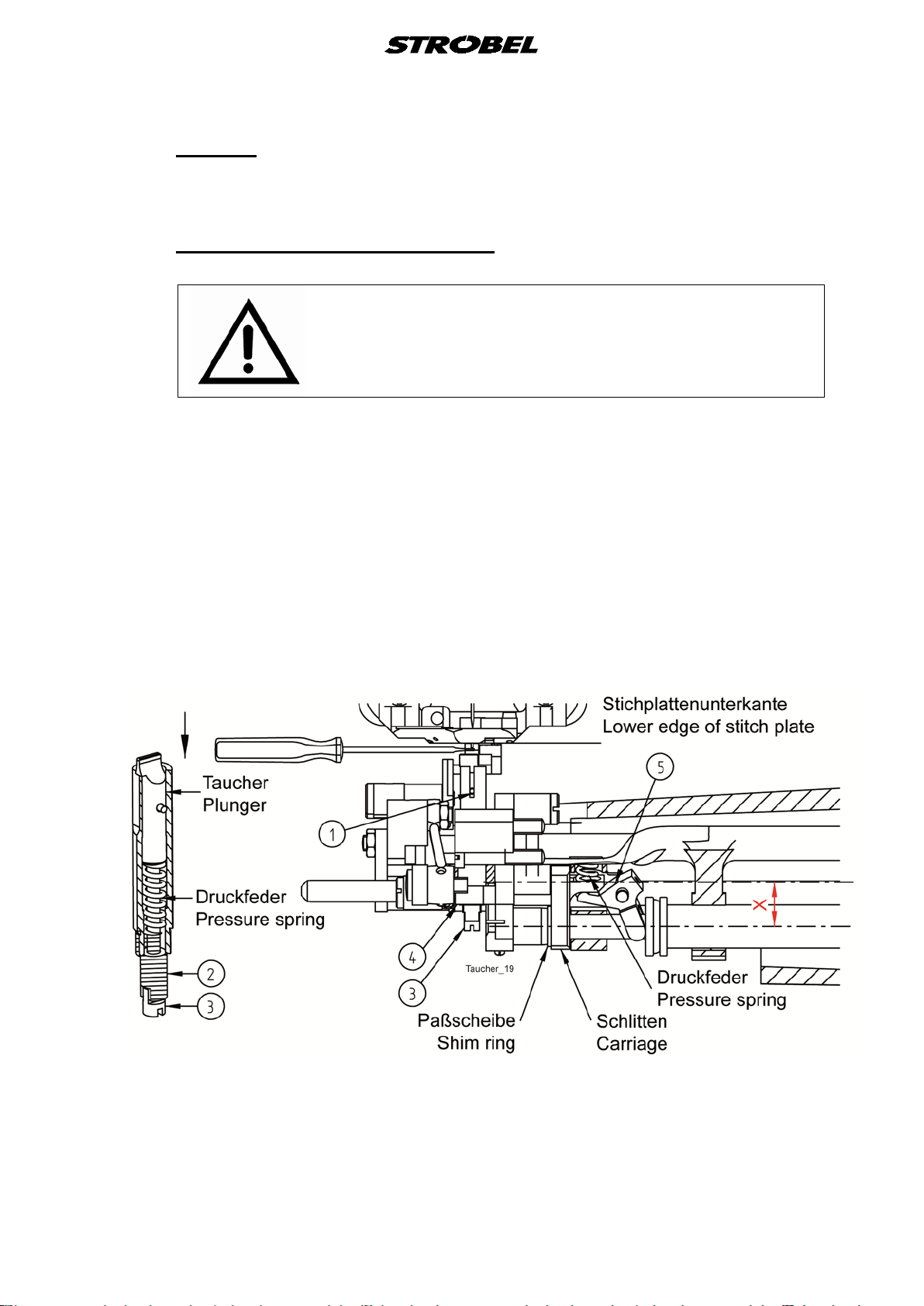
3.7.2
Fitting the plunger (Fig. 10)
Fitting takes place in reverse order.
However, the following points must be observed for precise adjustment:
a) the cylindrical pin (1) must engage in the groove of the plunger sleeve.
b) Turn stitch-depth adjustment knob (1) (Fig. 12) clockwise, as far as the
stop (highest position).
c) Turn plunger check screw (3) so far into the plunger, that when its double-
edged surface engages in the groove of the plunger adjustment screw (2),
the needle is raised 0.2 - 0.3 mm from the plunger.
d) The plunger reaches its highest position when the tip of the needle is
approx. 2 mm towards the middle of the plunger.
The plunger remains still until the needle point is 2 mm towards the centre
of the plunger.
This value is set by the position of the slide support (5), but care must be
taken that no double stroke occurs, i.e. the slide support must not move
beyond the upper dead point (±0.01 tolerance). It is drilled on the shaft,
i.e. the first threaded pin in the direction of rotation has a tip.
e) Factory adjustment of the plunger pressure: Screw for plunger adjustment
flush with the plunger guide (4).
Turning the plunger check screw, including the plunger adjustment screw,
clockwise, increases plunger pressure. Turning it anti-clockwise reduces
plunger pressure.
3.7.3
Adjusting plunger motion (Fig. 11)
Set plunger motion on plunger shaft in such a way that the pressure exerted
axially by pull-back spring (2) will always by taken over from the pressure
bearing (4) on the right hand above the set ring (5) . Play between disk (1) and
slide (3) should be about 0.1 mm.
The adjustment screw (2) (Fig. 12) must be limited by set screw (5) (Fig. 12),
the counter nuts (3) (Fig. 12) and the adjustment knob (1) (Fig. 12) so that slide
(3) is adjustable in its crank radius (= x in Fig. 10) from
13 - 16 mm. However, the pullback spring (2) should not be excessively
contractet, to avoid gears being placed one on top of the other, whereby
jamming and / or damaging of the slide edges would result.
21 MA_218D-TP-R_A4_181015_en
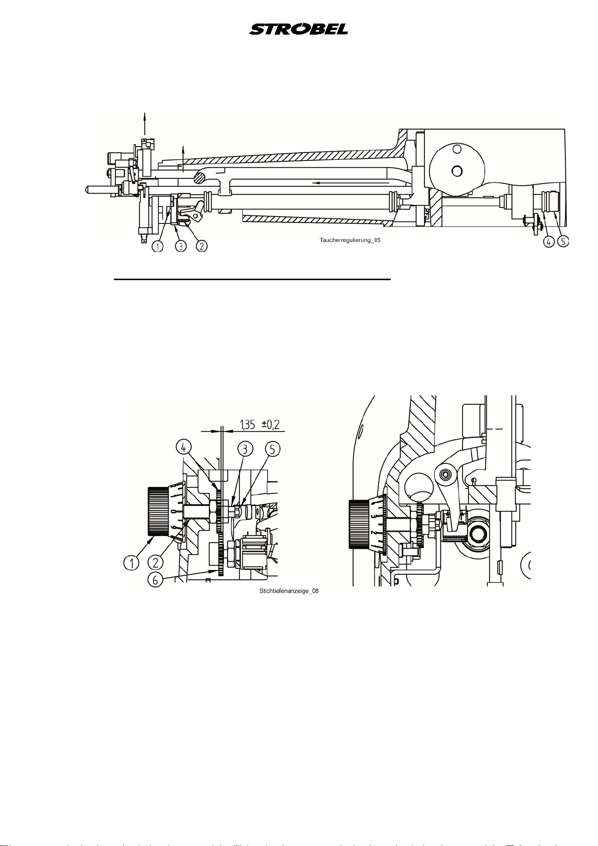
Fig. 11
3.7.4
Adjusting the digital stitch depth (Fig. 12)
If the adjustment knob (1) is turned clockwise as far as the stop, the toothed
wheel (6) must be screwed tightly onto the shaft of the helical potentiometer so
that a value of between 003 and 006 is displayed on the digital display, and the
distance to the toothed wheel (4) is approx.
1.35 ±0.2 mm.
Fig. 12
22 MA_218D-TP-R_A4_181015_en

3.8
Setting the plunger lowering (Fig. 13, Fig. 14, Fig. 15)
For larger sewing material thickening, sometimes the stitch depth of a stitch
should be reduced over a shorter or longer section. By adjusting the scale on
the right of the stand, the plunger can be lowered from 0 to up to 3.8 mm by
pushing a button. To do so, the thread tension is increased by an additional
thread tension.
To set the plunger lowering, cover (3) and the lower-arm cover must be
removed and the needle tip must be moved to the centre of the plunger using
the handwheel.
Set eccentric bolt (1) (Fig. 13) to approx. 45° and fix with threaded screw (2)
(Fig. 13) in the bearing.
Fig. 13
23 MA_218D-TP-R_A4_181015_en

Set the plunger to the highest possible point and adjust the eccentric (1)
(Fig. 14) to approx. 15° at the stop of scale (2) (Fig. 14) at pin (3) (Fig. 14).
Fix the scale in this position on the eccentric.
Fig. 14
24 MA_218D-TP-R_A4_181015_en
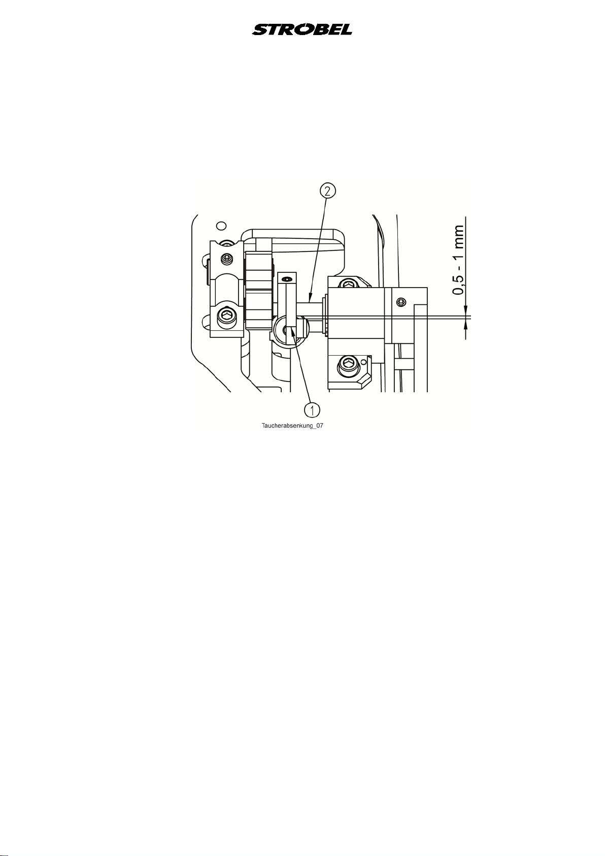
Lever (1) (Fig. 15) on which the cylinder hangs must be set so that there is a
free space of at least 0.5 to 1 mm between piston rod and eccentric (2) (Fig.
15). Secure lever (1) (Fig. 15) in this position on the eccentric with both
threaded screws.
Fig. 15
The plunger should travel a plunger path of at least 3.8 mm by adjusting the
scale.
25 MA_218D-TP-R_A4_181015_en

3.9
3.9.1
Thread spreader
It is possible to produce a cross-stitch using the thread spreader. The two
fingers of the thread spreader take hold of the thread between the sewing
material and the eye of the needle and place it under slight tension, at an angle
to the movement of the needle, in a groove in the needle plate.
After leaving the sewing material, the needle passes over this thread, the
needle thread is linked to the bobbin thread and needle thread presented by the
thread spreader lies under the link.
Setting the thread spreader (Fig. 16)
Attention!
Switch off machine electrically!
If correctly set, the thread spreader points cannot come into contact with the
needle plate, the plunger, the shuttle bridge, the needle or the sewing material.
Since if often happens that the insert tips break off, these can easily be
replaced.
New insert tips must be adapted to the machine and great care should be taken
that needle plate and tips are not damaged.
The insert tips can only be bent upwards from the middle, because the lower
end is hardened, and would break if bent.
Slowly turn machine by hand and check that thread spreader is running freely.
Fig. 16
26 MA_218D-TP-R_A4_181015_en

3.10
3.10.1
Seam lock
Attention!
Switch off machine electrically!
Attention!
Danger of finger bruises in the area of pneumatically
operated parts.
General (Fig. 17)
Refer to the sewing drive instructions for the parameter settings of the start and
end backtacks.
Screw (1) and hexagonal nut (2) are used to set lever (3) close.
Bolt (4) blocks or releases the lever (3). When the bolt released the lever, the
machine can tack.
The bolt should move easily by the pneumatic cylinder in the bore hole of the
flange (5).
Fig. 17
27 MA_218D-TP-R_A4_181015_en

3.11
3.11.1
3.11.2
Pneumatic venting
Attention!
Danger of finger bruises in the area of pneumatically
operated parts.
General
To vent the machine, pneumatic venting can be supplied in place of the knee
lever.
On releasing the pedal to activate the motor, the machine moves into position
and vents pneumatically.
In this position, plunger, feed and presser plate must all be at the same level.
Pressing the pedal forward closes the vent and the machine starts to sew.
Normal tread position.
Setting the lifting
3.12
Reduce the lifting speed at the one-way restrictor so that there is no hard noise
when the plunger, the presser plate and the feed is lowered.
Sewing drive
Separate operating instructions with programming instructions and wiring
diagrams are supplied with the sewing drive.
28 MA_218D-TP-R_A4_181015_en

Nähleuchte (allg.)
sewing light (gen.)
Netzanschluss
power connection
258.00.35
Netz-Anschlussplan Kl. allg.
(AB611A mit/ohne Nähleuchte allg.)
Mains connection plan cl. gen.
(AB611A with/without sewing light gen.)
Kabelbefestigung mit Kabelbinder
cable mounting with cable strap
3x 293.0290
Kabelzugentlastung
cable strain relief
193.0992
Rechtes Gehäuseteil
right casing
Linkes Gehäuseteil
left casing
Steuerkasten
control box
Efka-AB611A
Sicherung (8,0A M)
fuse (8,0A M)
293.0978
195.0042
gn-ge / gn-ye
bl / bu
br / bn
bl / bu
br / bn
bl / bu
br / bn
F 8,0A M
F 8,0A M
ST2
+5V / 0,2A
0V
+15V / 0, 3A
+24V(1)
+24V(1)
+24V(1)
0V
POS1Q
POS2Q
G1Q
3A
+24V(1)
+24V(1)
3A
0,5A
0,5A
0,5A
6,5A
6,5A
3A
3A
0,5A
0,5A
0,5A
0,5A
LÜ ( MV1 )
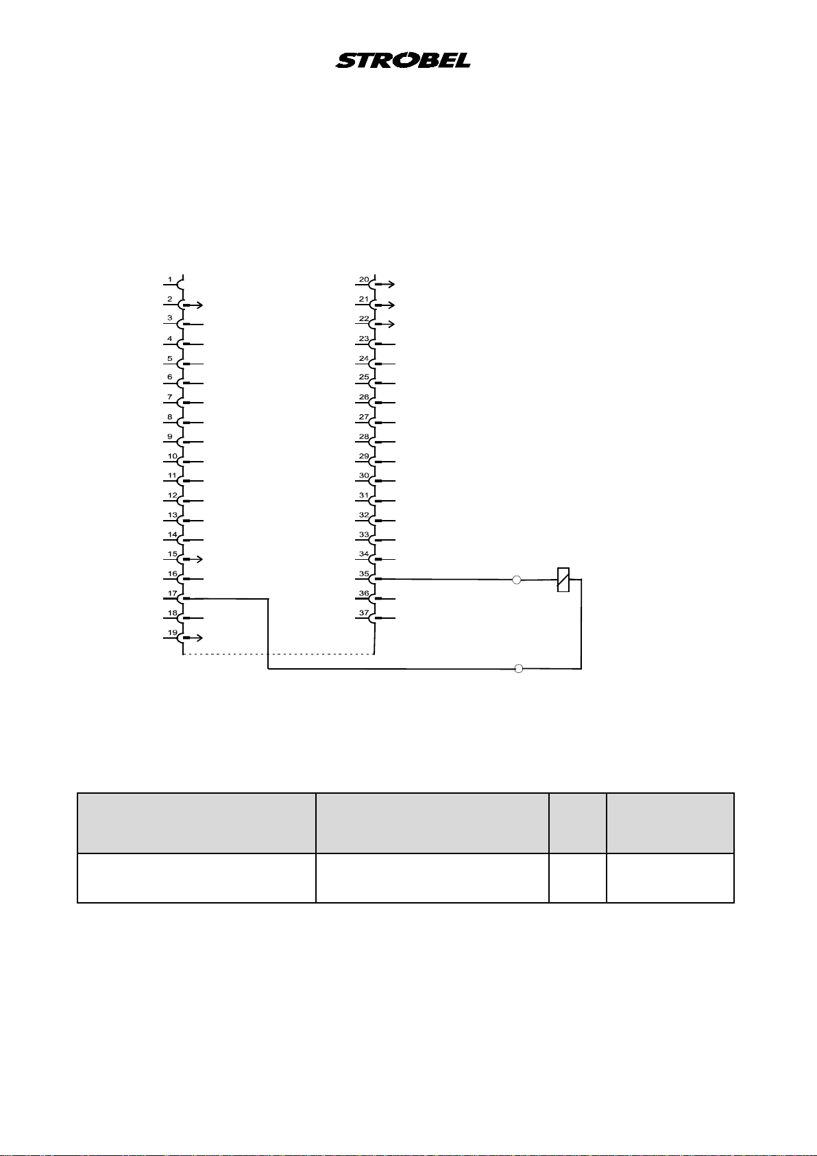
258.21.66en
Electrical connection plan cl. 300
(DC1200-AB611A)
Control box Efka drive
(1) Nominal voltage 24V, idle voltag e max. 30V
Designation
Strobel operating manual
Lifting (LÜ) Press foot lifting (FL) 35
Designation
Efka operating manual
PIN
37 pin
Sub-D
17
Colour code
connection cable
White
brown

258.10.16
Elekrischer Schaltplan - Taucherabsenkung
Kl. 218D-TP Ausf. 3 und Kl. 325-40D-TP ab Ausf. 9
Electrical wiring diagram - Plunger lowering
Cl. 218D-TP version 3 and cl. 325-40D-TP as of version 9
ST2
1
+24V
+24V
br bn
17
18
ws wh
0V
19
ws wh
35
37
vom Nähantrieb
from sewing drive
gn gn
R
gn gn
ws wh
br bn br bn
ws wh
gn gn
gn gn
br bn
S1
1V2 (TP)
1V1 (LÜ)
195.0027
1V1 Magnetventil "Lüftung" (LÜ) solenoid valve "lifting" (LÜ)
1V2 Magnetventil "Taucherabsenkung" (TP) solenoid valve "plunger lowering" (TP)
R Widerstand resistor
S1 Schalter mit LED switch with LED
ST2 Stecker Steuerkasten (Nähantrieb) plug control box (sewing drive)

259.00.62
Pneumatischer Schaltplan
Kl. 218D-TP-R ab Ausf. 4
Pneumatic circuit diagram
cl. 218D-TP-R as of version 4
A
R
B
P
5
1A
3
1V
6
1A
e
h
c
u
lä
h
c
)
n
S
e
d
n
l
n
h
e
u
k
ic
c
e
se
e
z
h
n
c
D
n
u
e
m
(B
A
k
3
1A
B
A
A
R
B
P
4
1A
2
1A
1
1A
10
1V
2
1V
A
R
P
B
r
a
b
1
1V
6
1
Z
0
x
a
m
r
a
b
10
195.0549
0 Z 1 Wartungseinheit service unit
1 V 1 4/2-Magnetventil "Lüftung" 4/2-solenoid-way valve "lifting"
1 V 2 4/2-Magnetventil "Taucherabsenkung" 4/2-solenoid-way valve "plunger lowering"
1 V 3 4/2-Magnetventil "Riegel" 4/2-solenoid-way valve "spot tack"
1 V 10 Drosselrückschlagventil "Lüftung" throttle non-return valve "lifting"
1 A 1 Zylinder "Lüftung" cylinder "lifting"
1 A 2 Zylinder "Fadenspannung" cylinder "thread tension"
1 A 3 Zylinder "Taucherabsenkung" cylinder "plunger lowering"
1 A 4 Zylinder "Zusatz-Fadenspannung" cylinder "optional thread tension"
1 A 5 Zylinder "Riegel" cylinder "spot tack"
1 A 6 Zylinder "Fadenspannung Riegel" cylinder "thread tension spot tack"

259.10.62
Pneumatischer Bauschaltplan
Kl. 218D-TP-R ab Ausf. 4
Pneumatic construction circuit diagram
cl. 218D-TP-R as of version 4
293.0469 1 Schalldämpfer R 1/8 silencer R 1/8
293.0470 1 Doppelnippel R 1/8 nipple R 1/8
193.0473 1000 PA-Schlauch Ø6 PA hose Ø6
193.0478 3000 PA-Schlauch Ø8 PA hose Ø8
293.0772 3 Verschlußschraube R 1/8 lock screw R 1/8
293.0837 4 L-Einschraubanschluss R 1/8-4 L-threaded connection R 1/8-4
293.0838 2 Y-Steckanschluss Ø4 Y-plug connection Ø4
293.0850 3 L-Einschraubanschluss R 1/8-6 L-threaded connection R 1/8-6
293.0853 4 L-Einschraubanschluss M5-4 L-threaded connection M5-4
293.0855 1 G-Steckanschluss 6-4 G-plug connection 6-4
293.0857 3 G-Einschraubanschluss M5-4 threaded connection M5-4
293.0905 1 Y-Steckanschluss Ø6 Y-plug connection Ø6
293.0975 1 Wartungseinheit service unit
196.0716 7800 PA-Schlauch Ø4 PA hose Ø4
293.0980 2 L-Schott-Verschraubung Ø8 L-bulkhead union Ø8
297.0170 1 Schnellverschlusskupplung Ø8 coupling Ø8
298.0075 1 Spannzylinder clamping cylinder
298.0077 1 Drosselrückschlagventil R 1/8 throttle non-return valve R 1/8
298.0211 2 Miniatur-Zylinder miniature cylinder
898.0211 1 Miniatur-Zylinder miniature cylinder
398.0301 1 Miniatur-Zylinder miniature cylinder
298.0360 1 Miniatur-Zylinder miniature cylinder
298.0510 3 4/2-Wege Magnetventil 4/2-solenoid-way valve
298.0511 1 Eingangsmodul G1/8 links input module G1/8 left
298.0512 1 Eingangsmodul G1/8 rechts input module G1/8 right
398.0301
293.0853
195.0550
4
O
140 lg (A)
196.0716
A
6
19
O
4
.0
7
16
4
O
196.0716
1
193.0473 O6
4
O
170 lg (B)
196.0716
B
293.09802x
Deckel / cover
898.0211
optional thread tension
O
4
6
.0
7
16
Zusatz-Fadenspannung
19
1
298.0512
298.0360
plunger lowering
Taucherabsenkung
4
4
O
196.0716
B
5
4
O
293.08382x
196.0716
3
2
293.08374x
293.07723x
5
293.0857
4
A
Riegel
spot tack
298.02112x
293.08572x
R
TP
thread tension
Fadenspannung
3
O
4
6
19
.0
7
16
2
6
19
O
4
.0
7
16
293.08532x
Magnetventil
solenoid valve
293.0853
6
298.05103x
O
298.0511
293.0469
193.0473
293.08502x
293.0855
293.0905
(293.0850)
service unit
Wartungseinheit
193.0478 O8 - 3000 lg
293.0975
(293.0841)
293.0850
298.0077
297.0170
293.0470
lifting
Lüftung
298.0075

Elekrischer Schaltplan - Taucherabsenkung und Punktriegel
Electrical wiring diagram - Plunger lowering ans spot tack
vom Nähantrieb
from sewing drive
0V
+24V
+24V
+24V
0V
ST2
1
2
3
4
5
6
7
8
9
10
11
12
13
14
15
16
17
18
19
20
21
22
23
24
25
26
27
28
29
30
31
32
33
34
35
36
37
258.10.25
Kl. 218D-TP-R ab Ausf. 4
Cl. 218D-TP as of version 4
ws
wh
Sperrdiode
R
br
bn
ws
wh
ws
wh
bl
bu
R
gn
gn
br
bn
br
bn
gn
gn
gn
gn
ws
wh
br
bn
ws
wh
br
bn
ws
wh
br
bn
gn
gn
br
bn
br
br
bn
bn
gn
gn
S2 (R)
gn
gn
S1 (TP)
bl
bu
1V3 (R)
br
bn
1V2 (TP)
1V1 (LÜ)
195.0060
1V1 Magnetventil "Lüftung" (LÜ) solenoid valve "lifting" (LÜ)
1V2 Magnetventil "Taucherabsenkung" (TP) solenoid valve "plunger lowering" (TP)
1V3 Magnetventil "Punktriegel" (R) solenoid valve "spot tack" (R)
R Widerstand resistor
S1 Schalter mit LED "TP" switch with LED "TP"
S2 Schalter mit LED "R" switch with LED "R"
ST2 Stecker Steuerkasten (Nähantrieb) plug control box (sewing drive)

258.21.24
Elektrischer Anschlussplan Kl. 170, 560, ZM
Digitalanzeige
Electric connection diagram cl. 170, 560, ZM
Digital display
Steck-Adapter EA 9044
socket adapter EA 9044
10
VSS
- +
ws / wh
1A
VDD
d
r
/
t
r
1
9 10
B
R2
137kΩ
Widerstand
resistor
ws / wh
gn / gn
br / bn
a
2
R1
5kΩ lin.
b
Drehpotentiometer
rotary potentiometer
1346
Kippschalter
flip switch
k
b
/
w
s
d
r
/
t
r
+
9V
Batterie
battery
198.0466


Und wir können noch mehr für Sie tun!
Unser Lieferprogramm bietet für jede Branche und
jegliche Anforderung genau die richtige Problemlösung.
And we can do a lot more for you!
Our range offers the correct problem solution for
every branch and for all requirements.
Für die Bekleidungsindustrie:
Ein- und ZweifadenHochleistungs-Saummaschinen
DoppelblindstichSaummaschinen
Zweifaden-BlindstichStafermaschinen
Roll- und Flachpikiermaschinen
Pikier-Automat
und
weitere Spezial-Nähmaschinen
For the clothing
industry:
Single and two thread high
performance hemming
machines
Bluff edge hemming machines
Two thread blind stitch felling
machines
Roll and at padding machines
Automatic lapel padding
machine
Für die Schuhverarbeitung:
Einfaden-Überwendlichmaschinen mit und ohne
Differentialtransport
For the shoe industry:
Single-thread overseaming machines with and without differential feed
Für Kürschnereien
und Pelzkonfektion:
Pelzschnellnäher
For the fur industry:
High-speed fur sewing machines
Für Heimtextilien:
Ein- und ZweifadenBlindstichmaschinen
For the home textiles
industry:
Single and two thread
blind stitch machines
Für die Polsterverarbeitung:
Ein- und ZweifadenÜberwendlichmaschinen
Ein- und ZweifadenBlindstichmaschinen
For the upholstery
industry:
Single and two thread
overseaming machines
Single and two thread
blind stitch machines
Für die Konfektion
technischer Textilien:
Ein- und ZweifadenÜberwendlichmaschinen
For the processing
of technical textiles:
Single and two thread
overseaming machines
and other special sewing
machines

Noch Fragen?
Dann rufen Sie uns an, schreiben Sie uns oder
kommen Sie einfach bei uns vorbei.
Sie können jederzeit weitere Informationen über
unsere Produkte anfodern oder die StrobelNähmaschinen in unserem Ausstellungsraum live
erleben. Wir freuen uns auf Sie!
Any further questions?
Then phone, write or simply come and see us. You
can have further information about our products at
any time, or experience the Strobel machines live in
our show room. We’re looking forward to meeting you!
Sp ez i al ma sch in en Gm bH
Postfach 1242
82168 Puchheim
Siemensstraße 3
82178 Puchheim
DEUTSCHLAND
www.strobel.biz
Telefon: +49 89 80096-0
Telefax: +49 89 80096-190
 Loading...