


For the professional user
Operating Instructions
Für den professionellen Anwender
Betriebsanleitung
Class:
Klasse:
141-30 Ausf. 6
141-40 Ausf. 7
Model:
Ausführung:
Machine number:
Maschinen-Nr.:
Dated:
Stand:
S p e z i a l m a s c h i n e n G m b H

The sign of quality
ou nd the Strobel trademark on every Strobel
Y
machine leaving our works. And with good reason.
This symbol is a guaranteen of the high quality of
our products. Quality which creates trust – trust
in our technology, our service and, not least of all,
in our good name.
Im Zeichen der Qualität
ie nden die Strobel-Schutzmarke auf jeder
S
Strobel-Maschine, die unser Werk verlässt.
Und das aus gutem Grund. Denn dieses Zeichen
garantiert Ihnen die hohe Qualität unserer
Produkte. Qualität, die Vertrauen schafft – in unsere
Technik, unseren Service und nicht zuletzt in unseren
guten Namen.

A decision with future
trobel clients know that they can expect a particularly
S
high standard of performance from our company and our
machines. Now you have settled for one of our products.
For us this is a source of encouragement and of obligation
to Justify your trust.
If you wish to prot from the performance and efciency of
your Strobel machine as long as possible, exact handling
and thorough care is necessary. For this reason we kindly
request that you read the operating instructions closely.
It provides all the information you need for trouble free
operation.
And if you do happen to need a spare part the enclosed
spare parts list gives a complete overview. It is clearly
classied according to components so that you can nd the
required part quickly and easily. In order to avoid errors we
request you to quote machine class, machine number and
part number completely on your spare part order.
We wish you lots of success in your work with your new
Strobel machine.
Spez ia lm as ch in en G mb H


1 BA_141-30-40_A6-7_140416_en

2 BA_141-30-40_A6-7_140416_en

Operating Instructions
STROBEL – Single Thread Overseam Machines
Class 141-30, 141-40
Contents
1 General notes on safety ............................................................................................ 4
2 General ..................................................................................................................... 6
2.1 Operating instructions ..................................................................................... 6
2.2 Class identification, serial number and orientation of the machine ................. 6
2.3 Range of application and intended use .......................................................... 6
2.4 Technical Data ................................................................................................ 7
3 Installation and putting into service ........................................................................... 8
3.1 Unpacking the machine .................................................................................. 8
3.2 Installation ...................................................................................................... 8
3.3 Sense of rotation (Fig. 2) .............................................................................. 10
3.4 Motor drive via V-belts .................................................................................. 10
3.4.1 Tensioning the V-belt ....................................................................... 10
3.4.2 Positions of the machine .................................................................. 11
3.5 First lubrication (Fig. 6 and F ig. 7) ................................................................ 13
4 Instructions for use .................................................................................................. 15
4.1 Needles and threads (see chart, point “2.4 Technical Data”) ....................... 15
4.2 Inserting the needle (Fig. 8) .......................................................................... 15
4.3 Threading and thread course (Fig. 1 and Fig. 8) .......................................... 16
4.4 Thread tension .............................................................................................. 17
4.5 Setting the stitch length ................................................................................ 17
4.6 Adjustment of material guide ........................................................................ 18
4.7 Inserting and removing the material (Fig. 11) ............................................... 20
5 Machine maintenance ............................................................................................. 21
5.1 Oil drain pipe ................................................................................................ 22
6 Variable sewing tools .............................................................................................. 24
7 Optional extras ........................................................................................................ 28
7.1 Control panel ................................................................................................ 28
Subject to change without prior notice
3 BA_141-30-40_A6-7_140416_en

1
General notes on safety
The non-compliance wi th the fol l owing notes on safety can lead to bodily
injuries or to damages of the machine.
1. The machine must only be operated by persons familiar with the relevant
operating instructions and who have been instructed accordingly.
2. Before commissioning also read the notes on safety and the operating
instructions of the sewing drive manufacturer.
3. The machine must only be operated according to its designation and not
without the appropriate guards; all explicit safety regulations must also be
observed.
4. For threading, for changing the reels, for exchanging sewing tools such as
needles, grippers, stitch plate, transport devices, if necessary cutter and
cutting block, for cleaning, when leaving the workplace and for
maintenance work, switch off main switch or pull mains plug. With a
mechanically operated coupling motor without activation lock, wait until the
motor has stopped.
5. General maintenance work must only be carried out by appropriately
instructed persons in accordance with the operating instructions.
6. Repair, modification and maintenance work must only be carried out by
qualified staff or by appropriately instructed persons.
7. During maintenance and repair work at pneumatic devices, the machine
must be disconnected from the pneumatic supply network. Exceptions are
only admissible during adjusting work and function test by appropriately
instructed qualified staff.
8. Work at the electrical equipment must only be carried out by qualified
staff.
9. Work at parts and devices under voltage is not allowed. Exceptions are
regulated by the regulation EN50110 (DIN VDE0105).
10. Modification or alteration at the machine must only be undertaken under
consideration of all explicit safety regulations.
11. Only spare parts released by us for use are to be used during repairs.
12. The commissioning of the upper part is prohibited until it has been
determined that the entire sewing unit complies with the regulations of the
EC guidelines.
4 BA_141-30-40_A6-7_140416_en

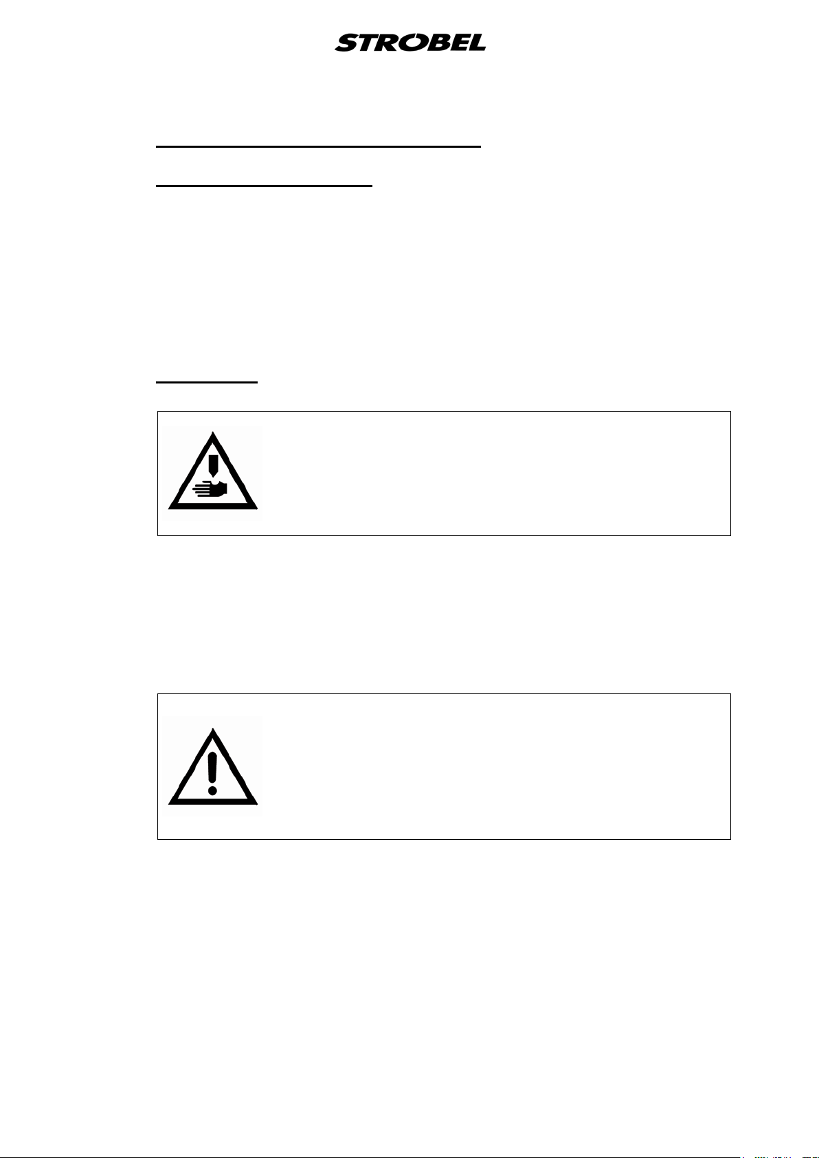
13. Warning notes in the operating instructions of the machine, which point
out special points of danger, are marked at the appropriate positions with
the safety symbol.
Warning notes in the operating instructions of the machine which point out
special dangers of injury for operating or qualified staff, are marked at the
appropriate positions with the symbol
It is essential that you observe and follow these notes as well as the
generally valid safety regulations.
5 BA_141-30-40_A6-7_140416_en

2
2.1
2.2
2.3
General
Operating instructions
Any person involved in the installation, operation, maintenance and repair of
the machine must have read and understood the operating instructions and
mainly the safety instructions before starting the machine. Please open the
illustrations at the beginning of these operating instructions, so you can follow
the illustrations step by step while reading the instructions.
Class identification, serial number a nd orientation of the machine
The operating side of the machine is the basis for descriptions referring to
sides. The class identification (type) as well as serial and model number (after
the dash) are located below the left handwheel. These data are also shown on
the front page of the operation instructions.
Range of applicati on a nd intended use
Class 141-30
Single Thread Overseaming Machine for sewing fur facings, heavy furs such as
lambskin, imitated furs and polishing wheels.
Class 141-40
High Speed Single Thread Overseaming Machine for fine fur stranding (let-out)
and general sewing operations.
6 BA_141-30-40_A6-7_140416_en

2.4
Technical Data
Number of stitches: Max mechanically admissible
Cl. 141-30 2800 min-1
Cl. 141-40 4200 min-1
Recommended rated speed:
Cl. 141-30 2300 min-1
Cl. 141-40 3600 min-1
Machine pulley diameter dw 80 mm
V-belt profile 10 x 6 mm
Stitch length Cl. 141-30 3 - 6 mm adjustable
Cl. 141-40 0.6 – 2.5 mm adjustable
Kind of stitch Single Thread Overseam
Needle system 459R
Needle size Cl. 141-30 110 - 130
Cl. 141-40 40 - 120
Recommended thread twisted polyester filament
Recommended thread size
Cl. 141-30 50 -10
Cl. 141-40 130 – 80, 40 - 10
Stitch type 501
Kind of feed rear cup drive
Pneumatic connection 10 bar
Operating pressure 5 – 6 bar
Required space 0.6 m x 1.06 m
Noise:
Average noise level at a speed of
Cl. 141-30 n = 2300 min-1 LpAm 84 dB(A)
Cl. 141-40 n = 3200 min-1 LpAm 85 dB(A)
Noise test according to DIN 45635-48-1 KL3
7 BA_141-30-40_A6-7_140416_en
instructions.
3
3.1
3.2
Installati on a nd put t ing into service
Unpacking the machine
Strobel machines are supplied either as complete units with head, stand and
motor, or head with motor only, or the head only.
Due to the high weight and to avoid damages during transport, complete units
are packed in several smaller cartons.
Machine head and motor are removed from the stand. Reel stand, rods, oil and
other accessories are packed into the stand packing. Make sure that all
accessories have been unpacked before throwing away any packing material.
Installation
ATTENTION!
Danger of bodily injuries or finger bruises through pulling in
of garments or hairs!
The machine may not be operated without belt guards for
head and motor.
Caution: Screw oil drain pipe 133.0764 to the lid 112.0085 before setting the
top part on the table top. (See point “5.1“)
If the frame is not delivered by us as well, but rather the machine set on a
different frame, then the table top needs to be prepared as can be seen in the
table-top diagram.
ATTENTION!
Before putting the machine into service make sure
that the electrical connecting data on the motor’s
name plate, your electric network, and all other connecting
values, e. g. for the air, correspond to
the data shown on the machine and the operating
8 BA_141-30-40_A6-7_140416_en

Fig. 1
All rust protection agents, such as Vaseline and similar agents have to be
wiped off carefully from the sewing tools before putting the machine into
service.
9 BA_141-30-40_A6-7_140416_en

3.3
Sense of rotation (Fig. 2)
The correct sense of rotation of the right hand wheel is clockwise in line of
vision on the hand wheel.
Fig. 2
3.4
3.4.1
Motor drive via V-belts
Tensioning the V-belt
Caution! Danger of injury!
When checking the belt tension, switch off the machine at
the mains. Do not operate the machine without the belt
guard. Otherwise there is a DANGER of crushing
fingers, of injuries to the body and of pulling in parts of
clothing.
The tensioning of the V-belt is carried out by swivelling the motor underneath
the table plate after releasing the retaining nut with SW 24.
The V-belt must not be tensioned too much, especially with the stop motor. You
should be able to depress it with light thumb pressure by about 2 cm.
Too little V-belt tensioning can impair the positioning of the machine and
therefore impair the function sequence.
10 BA_141-30-40_A6-7_140416_en

3.4.2
Positions of the machine
CAUTION! Danger of injury!
Danger of crushing fingers and needle through stitching as
well as pulling in of parts of clothing.
Keep fingers and hands away from moving parts when
setting the position generator and checking the positions
with switched-on machine.
General:
Stop motors require a position generator, which takes the mechanical setting of
the machine from the main screw and transmits this to the control of the motor.
(Fig. 2)
The correct position of the position generator to the flange is marked with a
spot of paint.
To adjust or to remove, release the two clamping screws (2), Fig. 2. tighten
these firmly prior to commissioning.
All Machines:
The machine requires two needle positions and, depending on the sewing
drive, possibly also a reference position.
Reference position (if required, i.e. sewing drive DC1500-ST220A (Fig. 3)):
The reference position must be set in such a way, that the point of the
needle in the direction of the insertion stitch closes with the outer table
edge.
Fig. 3
11 BA_141-30-40_A6-7_140416_en

Needle position (with stop outside the seam with pedal position "-2"
(Fig. 4)):
The needle position must be set in such a way, that the distance between
the outer table edge in the stitch direction and the tip of the needle is
about 10 mm.
Needle position is position 2 at the sewing drive.
Fig. 4
Needle position (with stop in and outside the seam with pedal position "0" (Fig.
5)):
The needle position must be set in such a way, that the distance between
the tip of the needle in the stitch direction and outer table edge is about 4
mm.
Needle position is position 1 at the sewing drive.
Fig. 5
12 BA_141-30-40_A6-7_140416_en

3.5
First lubrication (Fig. 6 and Fig. 7)
Remove outer and inner machine cover and pour in original STROBEL oil
supplied with the machine from above.
To take off the inner cover first pull out the small oil pipe in the oil rising pipe of
the pump.
The soecial STROBEL oil (viscositiy 46 c St) supplied with the machine should
always be used.
The required oil quantity is 0,5 liter. It is recommended to change the oil after
approx. six month operation.
The oiling points are automatically lubricated, therefore no maintenance
required.
Fig. 6
13 BA_141-30-40_A6-7_140416_en

When remounting the inner cover make sure that the lower part of the oil pipe is
pushed into the oil rising pipe of the pump. Otherwise the automatic lubrication
does not work and the machine will be heavily damaged through blocking of the
shafts in the bearings, etc.
Therefore follow the instructions carefully and, after filling the machine with new
oil, operate the machine for a short while and control the working of the
automatic lubrication through the oil inspection glass in the outer cover.
Fig. 7
14 BA_141-30-40_A6-7_140416_en

for using different needle types.
4
4.1
4.2
Instructions for use
Needles and threads
(see chart, point “2.4 Technical Data”)
The needle size to be used depends on the material to be sewn and on the
thread respectively. Needle type to be used is 459R.
When joining fused parts it may happen that the needle eye conglutinates,
which may affect the loop formation.
Thicker and harder material requires thicker needles.
Guaranteed remark!
This machine has been set and sewn off with genuine
Strobel needles.
No guarantee can be granted if the settings are modified
Inserting the nee dle (Fig. 8)
ATTENTION!
Switch off machine electrically and confirm that the
machine is really in standstill position by operating the
treadle for the motor control before changing the needle.
Otherwise danger of finger bruises and needle
throughstitches.
Introduce the needle with is horizontal groove pointing downwards, push it to
the rear until it strikes against needle stop 134.0205 (Fig. 8). Then the needle is
clamped by means of screw 171.0406 (Fig. 9).
15 BA_141-30-40_A6-7_140416_en

4.3
Threading and thread c ourse (Fig. 1 and Fig. 8)
ATTENTION!
Switch off machine electrically and confirm that the
machine is really in standstill position by operating the
treadle for the motor control before changing the needle.
Otherwise danger of finger bruises and needle
throughstitches.
After putting the bobbin on the supporting bolt of the reel stand, the thread is
guided through the eye of thread guiding arm. (Fig. 1)
Further pass it through thread guide 184.0078 (depending on thread and
material through 1 to 3 holes) and thread tension discs 184.0049 to thread
guide 184.0161 and through thread eye 184.0125.
Fig. 8
Fig. 9
16 BA_141-30-40_A6-7_140416_en

Then guide the thread beneath pin 160.0079 at needle bar head and put it
round thread clamping screw 138.0081. After hooking it into needle set plate
285.0054 (Cl.141-30), 285.0147 (Cl. 141-40) from the left to the right, the
thread is passed through the eye of the needle from below (Fig. 8).
Thread guide 184.0078 should always be in a vertical position to obtain a large
looping angle between the thread tension discs.
4.4
4.5
Thread tension
Depending an quality, nature and thickness of the thread, thread tension is set
by means of tension nut 279.0624 (
tight tension.
Fig. 2). A thick and strong thread requires
Setting the stitch length
ATTENTION!
Switch off machine electrically and make sure that it is
really in standstill position by healing the tradle for the
motor control before setting the stitch length. Otherwise
danger off finger bruises and needle thoughstitches.
As shown in Fig. 7, the stitch length can be adjusted by means of stitch
adjusting knob 344.0089 in the inside of the left handwheel, which is equipped
with pointer 124.0080 showing through the “S” slot in the handwheel.
The handwheel has a scale according to which pointer 124.0080 has to be set.
The figures of this scale do not represent a certain stitch length in mm, but
serve as reference figures only. However, low figures mean smaller stitch
length and viceversa.
17 BA_141-30-40_A6-7_140416_en

4.6
Adjustment of material guide
Class 141-40
This machines are used for finest stranding operations.
(see point “2.3 Range of application and intended use”)
Attention!
Switch off machine electrically and confirm that the
machine is really in standstill position by operating the
treadle for the motor control.
Otherwise danger of finger bruises and needle
throughstitches.
As already mentioned, a height limit stop can be attached (see feed cup chart)
which, depending on the material to be sewn, can be set to the desired height.
It is important that the looper passes the material guide without striking it. (Fig.
10)
Fig. 10
18 BA_141-30-40_A6-7_140416_en

Fig. 11
19 BA_141-30-40_A6-7_140416_en

4.7
Inserting and re m ovi ng t he m a t e rial (Fig. 11)
ATTENTION! Danger!
The operating personnel should observe the sewing range
carefully during swing. Otherwise danger of finger bruises
and needle throughstitches.
When the machine is in standstill position and the needle is placed approx. 3
mm within the feed cup, by opening the front cup up to approx. 14 mm, by
either actuating the treadle or the pneumatic cup opening (depending on the
machine class) the sewing material can be inserted or removed easily.
Put the sewing material edge to edge and place it then up to the height limit
stop of the material guide, close the front cup and start sewing.
When using a stop motor the needle is positioned automatically after the
sewing process when heeling the treadle.
Only then the thread can be torn over the edge of the feed cup and then the
material can be removed, or the material is removed and the thread is cut using
scissors.
20 BA_141-30-40_A6-7_140416_en

5
Machine maintenance
Attention!
Switch off machine electrically and confirm that the
machine is really in standstill position by operating the
treadle for the motor control.
Otherwise danger of finger bruises and needle
throughstitches.
The machine is maintenancefree due to automatic lubrication (see “First
lubrication” point 0), only once a week dirt and hairs should be removed from oil
drain hole “D” to allow the oil coming from the needle bar to drain off. Also oil
splashing protector “C” should be cleaned (remove small cover at looper shaft),
to avoid that the oil is soaked up by the dirt and thus spoiling the material.
Checking the oil level:
Make sure that there is always
to submerge in the oil and to always bring the oil upwards.
A plastic receptacle with a capacity of exactly 1 liter is supplied with the
machine. After having filled the machine with one liter oil, the oil pump’s suction
piece is submerged in the oil.
Oil quantity and cleanness should be checked every six to twelve month
maximum.
sufficient
oil in the machine to enable the pump
If the oil is still clean enough, the oil quantity can be checked using the plastic
receptacle. Drain the oil into this receptacle an re-fill it into the machine if the oil
quantity is still correct. It is recommended to order a second oil container to
complete the oil quantity to one liter, if necessary.
The first oil change should be realized after about six month operation.
21 BA_141-30-40_A6-7_140416_en

5.1
Oil drain pipe
To facilitate machine maintenance, at the machine body or at the lower cover
respectively there is oil drain pipe 133.0764 going through the table top, thus
enabling to drain the oil without removing the machine head.
The oil drain pipe 133.0764 is sealed by means of seal ring 193.0530 and
screw 173.0772 (Fig. 13).
For machine assembly and for shipment the screw borings in cover 112.0085
are sealed by means of ring 193.0530 and screw 193.0772 as well as three
rings 190.0010 and screws 172.0521 each (Fig. 12).
Before mounting head to the table top screws 193.0772 and 172.0521 with the
seal rings have to be removed and the oil drain pipe with sealing washer
190.0178 has to be mounted and sealed (Fig. 13).
To drain the waste oil put a receptacle under the pipe and remove screw
193.0772 only. After having drained the oil screw on screw 193.0772 and seal
it.
Dispose of old oil properly!
ATTENTION! Danger!
Observe safety instructions under 1.3 and operating
instructions before starting any maintenance or repair
works. Failure to do so can result in serious bodily injuries.
After having drained the oil rinse the machine thoroughly with petroleum and
then refill with new oil.
When removing the inner cover, also oil pipe 196.0716 for the automatic
lubrication which comes from the oil pump through the inner cover with oil, is
removed (Fig. 6)
When re-mounting the inner cover please observe that the lower end of the
main oil pipe is put into the conical opening of the oil outlet piece of the oil
pump (Fig. 6). If you fail to do so the automatic lubrication does not work and
the machine may be damaged seriously by jamming of the shafts in the
bearings.
Therefore these instructions should be observed carefully and after refilling new
oil make sure the automatic lubrication works properly by briefly operating the
machine and controlling the class at the outer cover.
Before operating the machine make sure that all protection devices (e. g. cover,
belt-guard, etc.) are effective and that all screws are tightened.
22 BA_141-30-40_A6-7_140416_en

Fig. 12
Fig. 13
23 BA_141-30-40_A6-7_140416_en

6
Variable sewing tools
Attention!
Switch off machine electrically and confirm that the
machine is really in standstill position by operating the
treadle for the motor control.
Otherwise danger of finger bruises and needle
throughstitches.
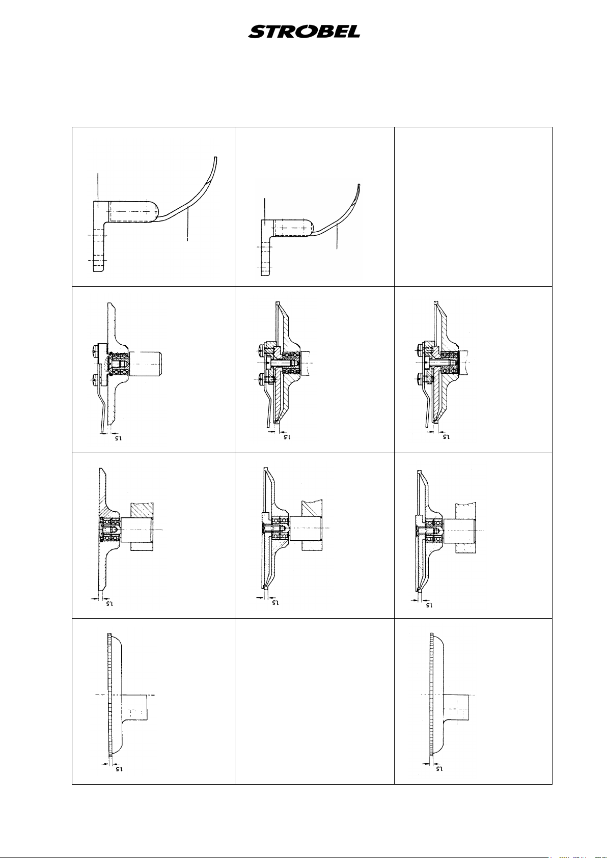
The following charts show all feed cups, front cups and material guides
available.
24 BA_141-30-40_A6-7_140416_en

186.0179
Extras
282.0203
front cup
∅ 60 – 1,5 pitch
with needle guard185.0123
Extras
382.0160
front cup ∅ 41 – 1,5 pitch
with nose 185.0128
186.0191
Material guide for
Extras
thicker material
Extras
282166
front cup
∅ 40 – 0,6 pitch
with needle guard 185.0125
682.0162
front cup
∅ 40 – 0,6 pitch
with height limit stop 186.0275
282.0160
front cup for thicker material
∅ 41 – 1,5 pitch
182.0015
feed cup for attaching fur
collars and fur trimmings
∅ 60 – 1,5 pitch
Cl. 141-30
214.0463
feed cup arm
complete, suitable
for front cup 282.0203
of Cl. 141-30
Cl. 141-40
282.0162
182.0025
front cup
∅ 40 – 0,6 pitch
feed cup
∅ 60 – 0,6 pitch
25 BA_141-30-40_A6-7_140416_en
186.0179
186.0179
Extras
Extras
Extras
186.0200
482.0161
front cup
material guide
Extras
∅ 60– 0,6 pitch
with height limit stop 186.0276
Extras
186.0315
482.0163
material guide
Extras
front cup ∅ 60 – 0,6 pitch
with needle guard 185.0123
and height limit stop 186276
Extras
482.0164
front cup ∅ 60 – 1,0 pitch
with needle guard 185.0149
and height limit stop 186.0276
282.0161
Cl. 141-40
front cup
∅ 60 – 0,6 pitch
214.0463
feed cup arm
182.0025
feed cup
∅ 60 – 0,6 pitch
complete, suitable
282.0163
front cup
∅ 60 – 0,6 pitch
with needle guard 185.0123
Extras
for all front cups
of Cl. 141-40
282.0164
182.0024
front cup
∅ 60 – 1,0 pitch
with needle guard 185.0149
feed cup
∅ 60 – 1,0 pitch
26 BA_141-30-40_A6-7_140416_en

Extras
482.0214
front cup
∅ 40– 0,6 pitch
Extras
Extras
with height limit stop 186.0275
Extras
382.0219
front cup ∅ 60 – 0,6 pitch
with needle guard 185.0123
and height limit stop 186.0276
Extras
282.0219
front cup
∅ 60 – 0,6 pitch
282.0214
Extras
Cl. 141-40
front cup
∅ 40 – 0,6 pitch
182.0215
feed cup
∅ 60 – 0,6 pitch
with needle guard 185.0123
Extras
282.0180
182.0179
front cup
∅ 60 – 1,0 pitch
with needle guard 185.0123
feed cup
∅ 60 – 1,0 pitch
27 BA_141-30-40_A6-7_140416_en

7
7.1
Optional extras
Control panel
298.0542 Control panel for a more comfortable controlling of the compact drive
28 BA_141-30-40_A6-7_140416_en


Und wir können noch mehr für Sie tun!
Unser Lieferprogramm bietet für jede Branche und
jegliche Anforderung genau die richtige Problemlösung.
And we can do a lot more for you!
Our range offers the correct problem solution for
every branch and for all requirements.
Für die Bekleidungsindustrie:
Ein- und ZweifadenHochleistungs-Saummaschinen
DoppelblindstichSaummaschinen
Zweifaden-Blindstich-
Stafermaschinen
Roll- und Flachpikiermaschinen
Pikier-Automat
und
weitere Spezial-Nähmaschinen
For the clothing
industry:
Single an two thread high
performance hemming
machines
Bluff edge hemming machines
Two thread blind stitch felling
machines
Roll and at padding machines
Automatic lapel padding
machine
and other special sewing
machines
Für die Schuhverarbeitung:
Einfaden-Überwendlichmaschinen mit und ohne
Differentialtransport
For the shoe industry:
Single-thread overseaming machines with and without differential feed
Für Kürschnereien
und Pelzkonfektion:
Pelzschnellnäher
Pelzpikiermaschine
Futterstafermaschine
For the fur industry:
Rapid fur sewing machines
Fur padding machine
Lining felling machine
Für Heimtextilien:
Ein- und ZweifadenBlindstichmaschinen
For the home textiles
industry:
Single and two thread
blind stitch machines
Für die Polsterverarbeitung:
Ein- und ZweifadenÜberwendlichmaschinen
Ein- und ZweifadenBlindstichmaschinen
For the upholstery
industry:
Single and two thread
overseaming machines
Single and two thread
blind stitch machines
Für die Konfektion
technischer Textilien:
Ein- und ZweifadenÜberwendlichmaschinen
For the processing
of technical textiles:
Single and two thread
overseaming machines

Noch Fragen?
Dann rufen Sie uns an, schreiben Sie uns oder
kommen Sie einfach bei uns vorbei.
Sie können jederzeit weitere Informationen über
unsere Produkte anfodern oder die StrobelNähmaschinen in unserem Ausstellungsraum live
erleben. Wir freuen uns auf Sie!
Any further questions?
Then phone, write or simply come and see us. You
can have further information about our products at
any time, or experience the Strobel machines live in
our show room. We’re looking forward to meeting you!
Spezi a l m a s c hinen G m b H
Postfach 1242
82168 Puchheim
Siemensstraße 3
82178 Puchheim
DEUTSCHLAND
www.strobel.biz
Telefon: +49 89 80096-0
Telefax: +49 89 80096-190
 Loading...