


For the professional user
Mechanic‘s Instructions
Für den professionellen Anwender
Mechanikeranleitung
Class:
Klasse:
Model:
Ausführung:
Machine number:
Maschinen-Nr.:
Dated:
Stand:
141-23EV Ausf. 10
141-30 Ausf. 6
141-40 Ausf. 7
141-50 Ausf. 3
142-30 Ausf. 6
142-40 Ausf. 5
S p e z i a l m a s c h i n e n G m b H

The sign of quality
Y
ou nd the Strobel trademark on every Strobel
machine leaving our works. And with good reason.
This symbol is a guaranteen of the high quality of
our products. Quality which creates trust – trust
in our technology, our service and, not least of all,
in our good name.
Im Zeichen der Qualität
ie nden die Strobel-Schutzmarke auf jeder
S
Strobel-Maschine, die unser Werk verlässt.
Und das aus gutem Grund. Denn dieses Zeichen
garantiert Ihnen die hohe Qualität unserer
Produkte. Qualität, die Vertrauen schafft – in unsere
Technik, unseren Service und nicht zuletzt in unseren
guten Namen.

A decision with future
S
trobel clients know that they can expect a particularly high standard of performance from our company
and our machines. Now you have settled for one of
our products. For us this is a source of encouragement
and of obligation to Justify your trust.
If you wish to prot from the performance and
efciency of your Strobel machine as long as possible,
exact handling and thorough care is necessary. For this
reason we kindly request that you read the operating
instructions closely. It provides all the information you
need for trouble free operation.
And if you do happen to need a spare part the enclosed
spare parts list gives a complete overview. It is clearly
classied according to components so that you can nd
the required part quickly and easily. In order to avoid
errors we request you to quote machine class, machine
number and part number completely on your spare part
order.
We wish you lots of success in your work with your
new Strobel machine.
S p e z i a l m a s c h i n e n G m b H


Mechanic’s instructions
STROBEL Classes 141-23EV, -30, -40, -50, 142-30, -40
Contents
1 General notes on safety ............................................................................................ 5
2 General ..................................................................................................................... 7
2.1 Operating instructions ..................................................................................... 7
2.2 Class identification, serial number and orientation of the machine................. 7
2.3 Range of application and intended use .......................................................... 7
2.4 Technical Data ................................................................................................ 9
2.5 Brief setting instructions ............................................................................... 10
3 Disassemble the machine ....................................................................................... 11
3.1 Disassemble the main shaft (Fig. 1 and Fig. 2) ............................................ 11
4 Assemble the Machine ............................................................................................ 13
4.1 Mount the shaft (Fig. 1) ................................................................................ 13
4.2 Mount stitch regulating eccentric 353.0031 .................................................. 13
4.3 Adjust stitch regulating bolt 137.0014 for stitch adjustment .......................... 15
4.4 Adjust needle- and feed motion .................................................................... 15
4.5 Looper motion............................................................................................... 16
4.5.1 Adjust the looper motion .................................................................. 16
4.5.2 Adjust the looper eccentric (on single thread machines).................. 17
4.5.3 Adjust the looper eccentric (on two tread machines) ....................... 17
4.5.4 Adjust the front crank ....................................................................... 18
4.5.5 Set the looper in its front position to the feed cup ............................ 19
4.5.6 Adjust stroke of loop ........................................................................ 19
4.5.7 Adjust the front bearing block........................................................... 19
4.5.7.1 Basic dimensions for front and rear bearing block ........... 19
4.5.8 Adjust the rear bearing block ........................................................... 20
4.6 Adjust height of rear feed cups ..................................................................... 20
4.7 Mount the front feed cup .............................................................................. 20
4.8 Length adjustment of bar 133.0851 between stitch regulation rod and free
wheeling ....................................................................................................... 20
4.9 Thread lifting mechanism at needle bar head .............................................. 20
4.10 Spring tension at feed cup support arm 333.0114 ........................................ 21
4.10.1 Plate arm lifting ................................................................................ 21
4.11 Needle setting ............................................................................................... 22
4.11.1 Adjusting needle height (Fig. 10 and Fig. 11)................................... 22
4.12 Chaniging the looper .................................................................................... 23
4.13 Maintenance ................................................................................................. 24
4.14 General Data ................................................................................................ 24
1 MA_141_142_A10-6-7-3-6-5_130617_en

5 Notes on repair and adjustment .............................................................................. 27
5.1 Transport plate assembly ............................................................................. 27
5.2 Exchanging the transport plate ..................................................................... 27
5.3 Mounting and setting instructions for STROBEL gathering device No.
314.0399 ...................................................................................................... 28
2 MA_141_142_A10-6-7-3-6-5_130617_en

Appendix
Circuit diagrams
Connecting the sewing ma chine:
259.00.16 Pneumatic circuit diagram Cl. 142
259.10.16 Pneumatic construction circuit diagram Cl. 142
Connecting digital display:
258.21.27 Electric connection diagram Cl. 141 – digital display
Subject to change without prior notice
3 MA_141_142_A10-6-7-3-6-5_130617_en

4 MA_141_142_A10-6-7-3-6-5_130617_en

1 General notes on safety
The non-compliance wi th the fol l owing notes on safety can lead to bodily
injuries or to damages of the machine.
1. The machine must only be operated by persons familiar with the relevant
operating instructions and who have been instructed accordingly.
2. Before commissioning also read the notes on safety and the operating
instructions of the sewing drive manufacturer.
3. The machine must only be operated according to its designation and not
without the appropriate guards; all explicit safety regulations must also be
observed.
4. For threading, for changing the reels, for exchanging sewing tools such as
needles, grippers, stitch plate, transport devices, if necessary cutter and
cutting block, for cleaning, when leaving the workplace and for
maintenance work, switch off main switch or pull mains plug. With a
mechanically operated coupling motor without activation lock, wait until the
motor has stopped.
5. General maintenance work must only be carried out by appropriately
instructed persons in accordance with the operating instructions.
6. Repair, modification and maintenance work must only be carried out by
qualified staff or by appropriately instructed persons.
7. During maintenance and repair work at pneumatic devices, the machine
must be disconnected from the pneumatic supply network. Exceptions are
only admissible during adjusting work and function test by appropriately
instructed qualified staff.
8. Work at the electrical equipment must only be carried out by qualified
staff.
9. Work at parts and devices under voltage is not allowed. Exceptions are
regulated by the regulation EN50110 (DIN VDE0105).
10. Modification or alteration at the machine must only be undertaken under
consideration of all explicit safety regulations.
11. Only spare parts released by us for use are to be used during repairs.
12. The commissioning of the upper part is prohibited until it has been
determined that the entire sewing unit complies with the regulations of the
EC guidelines.
5 MA_141_142_A10-6-7-3-6-5_130617_en

13. Warning notes in the operating instructions of the machine, which point
out special points of danger, are marked at the appropriate positions with
the safety symbol.
Warning notes in the operating instructions of the machine which point out
special dangers of injury for operating or qualified staff, are marked at the
appropriate positions with the symbol
It is essential that you observe and follow these notes as well as the
generally valid safety regulations.
6 MA_141_142_A10-6-7-3-6-5_130617_en

2 General
2.1 Operating instructions
Any person involved in the installation, operation, maintenance and repair of
the machine must have read and understood the operating instructions and
mainly the safety instructions before starting the machine. Please open the
illustrations at the beginning of these operating instructions, so you can follow
the illustrations step by step while reading the instructions.
2.2 Class identification, s e rial number and or ientation of the machine
The operating side of the machine is the basis for descriptions referring to
sides. The class identification (type) as well as serial and model number (after
the dash) are located below the left handwheel. These data are also shown on
the front page of the operation instructions.
2.3 Range of applicati on a nd intended use
Class 141-23EV
Single Thread Overseaming Machine with gathering device for sewing insoles
to uppers of heavy weight textile and leather shoes up to total thickness
of 7 mm.
With appropriate optional features also suitable for "string lasting" and
California processing.
Class 141-30
Single Thread Overseaming Machine for sewing fur facings, heavy furs such
as lambskin, imitated furs and polishing wheels.
Class 141-40
High Speed Single Thread Overseaming Machine for fine fur stranding (let-out)
and general sewing operations.
Class 141-50
High Speed Single Thread Overseaming Machine for very fine stranding
(let-out) operations at fur.
7 MA_141_142_A10-6-7-3-6-5_130617_en

Class 142-30
Two Thread Cup Seaming Machine for sewing and overedging soft rubber
foam. Material thickness compressed state up to 4 mm. Also suitable for
clothing quilts and for decorative stitches of fur and leather garments.
Special version Class 142-30N
Two Thread Cup Seaming Machine for sewing of coated material for diving and
surfing suits (e.g. neoprene) for material thickness of 4 – 7 mm.
Class 142-40
Two Thread Cup Seaming Machine for sewing and overedging soft rubber
foam. Material thickness compressed state up to 2 mm. Also suitable for
clothing quilts and for decorative stitches of fur and leather garments.
8 MA_141_142_A10-6-7-3-6-5_130617_en

2.4 Technical Data
Recommended rated speed min-1
1800
2300
3600
2300
2400
Machine
dw 80
V-belt profile
10 x 6 mm
Stitch length (adjustable in mm)
3 - 6.5
3 - 6
0.6 - 2.5
3 - 6
1 - 4
Kind of stitch: Overseam
Single thread
Two thread
Needle system
134
459R
1738
Needle size
140
110 -
40 - 120
90, 100
55
Recommended thread
Twisted Polyester filament
Recommended thread size
40 - 20
50 -
130 - 80
40 - 20
120/2
Stitch type
501
502
Kind of feed
Back plate transport
Pneumatic connection
10 bar
Operating pressure
5 - 6 bar
Required space
0.6 x 1.06 m
of number of stitches n min-1
1800
2300
3200
2300
Number of stitches
Max mechanically admissible min
Machine pulley diameter
141-23EV
-1
2300
141-30
2800
130
10
141-40
4200
40 - 10
141-50
142-30
142-30N
2800
142-40
2800
Noise:
Average noise level at a speed
9 MA_141_142_A10-6-7-3-6-5_130617_en
LpAm
73 dB
LpAm
84 dB
LpAm
85 dB
LpAm
76 dB

2.5 Brief setting instructions
Setting data
141-23EV
141-30
141-40
141-50
142-30
142-40
A
Stitch length
3 - 6.5
3 - 6
0.7 - 2.7
0.6 -2.5
2.3 – 5.3
1 - 4
B
Stroke of loop
4.7
4.5 - 5
3.5
3.5
4.2
4.5
Needle point front
edge
Looper front position
edge
K
Looper movement
9.5 9 5.3
4.8
8.2
6.7
Looper movement to
center to looper point
Class
C
measured from cup
Looper height
L
inclusive shaft
H
measured from cup
22.6 20.5 18.5 16.8 18.8 17
11.5 8.2 7.5 5.5 11.5 9.7
142-30N
37 30.5 31.5 30.8 28.3 31
H + J Total looper travel 17.7 12.7 11 10.1 12.5 11.3
F
the right from needle
5.5 3 4.2 3.2 2.8 5.9
The clearence between the feed cups amount 12 – 14 mm.
10 MA_141_142_A10-6-7-3-6-5_130617_en

3 Disassemble the machine
3.1 Disassemble the main shaft (Fig. 1 and Fig. 2)
Before disassembling the main shaft, it is advisable to mark the exact position
of each part or screw, and to take the measures of both bearing support blocks
by means of a gauge, measuring from the front edge of the machine column.
(Measures a + b).
This will save you a lot of time when you assemble and adjust the machine.
(Fig. 1)
Not until now should the screws of the parts attached to the shaft be loosened
and the right handwheel be removed and the shaft, too, be pushed out to the
left by a withdrawal device.
Loosen the screws of the parts. Take off the right hand wheel. Pull the shaft
about 20 to 30 mm to the left and remove the remaining glue without displacing
the ball bearings. Then take off shaft.
The left handwheel with the stitch-regulating eccentric bolt does not need to be
removed. Be sure that the set screws 176.0632 located on both sides of the
regulating eccentric bolt (A) 132.0074 are removed; on machines that were built
before 1986, the screws 176.0620, 176.0619, and the setbolts 135.0078.
(Fig. 1 and Fig. 2)
NOTE! If not done yet, mark the position of guide disc 153.0031 and
regulating eccentric 132.0074.
The remaining glue can easily be removed from the shaft by using a cleanser,
e. g. Clorothene.
11 MA_141_142_A10-6-7-3-6-5_130617_en

Fig. 1
Fig. 2
12 MA_141_142_A10-6-7-3-6-5_130617_en

4 Assemble the Machine
4.1 Mount the shaft ( Fig. 1)
First, remove any grease from the shaft. Mount the parts in correct order onto
the shaft and put it into the machine column so that it sticks out about 30 mm
on the left. Then put a drop of “Loctite” on either end of the shaft, that is, on the
left end sticking out from the column, and on the ball bearing on the right.
(Loctite, Kapillar 290)
NOTE! The surfaces to be joined must be absolutely clean. Only then
you may fit the shaft completely into the machine column. Turn
it slightly, so that the glue on the ball bearing is evenly
absorbed. Fix stitch regulating eccentric (A) (fig.1).
See chapter “4.2 Mount stitch regulating eccentric 353.0031”.
Push the shaft to the left up to the stop, and fasten setting ring
246.0103 on the right of the shaft in order to eliminate any axial
play.
About an hour later when the glue (Loctite, Kapillar 260) is hard, you may
continue to assemble and adjust the machine. When assembling after a repair,
it is not necessary to take off the left hand wheel.
4.2 Mount stitch regulating eccentric 353.0031
Fit the left handwheel onto the shaft so that the first screw in direction of sewing
fits into the drill hole on the left of the shaft and point upwards.
Turn guide disc 153.0031 so that you can easily slide down set eccentric
132.0074. Then screw the first screw 176.0632 into the regulating eccentric, but
ensure that regulating bolt 137.0026 can still freely be turned in the shaft. Then
turn hand wheel with shaft by 180 degrees. Screw second screw 176.0532 into
the regulating eccentric right to the stop. Fasten guide disc 153.0031.
Push the shaft to the left up to the ball bearing, slide set collar 246.0103 on the
right shaft side all the way to the ball bearings, and tighten. The shaft is now
fastened.
Let stitch-regulating eccentric 137.0014 level out and tighten.
Fix two lubricated springs 161.0063 and bolts 135.0062 into the drill hole of the
hand wheel (Fig. 2, Fig. 3 und Fig. 4).
13 MA_141_142_A10-6-7-3-6-5_130617_en

Fig. 3
Fig. 4
Screw knob 344.0089 onto regulating bolt 137.0026 until it touches the hand
wheel. Then hold the knob while screwing out the regulating bolt until index
124.0080 stops at the knob (mark 5) long stitch, (Fig. 4) and easily visible
between handwheel and stand.
When properly adjusted, you can easily turn the regulation knob from the fixed
stop “long stitch” to the fixed stop “short stitch”.
Regulating eccentric 132.0074 must be set to the upper dead point, the index at
the hand wheel to mark 5. Finally, screw in lock nut 179.0614. (Fig. 4)
14 MA_141_142_A10-6-7-3-6-5_130617_en

4.3 Adjust stitch regulating bolt 137.0014 for stitch adjustm e nt
Eccentric (A) 353.0031 (Fig. 1) and bolt (B) 137.0014 (Fig. 4) have to be
adjusted to the specific stitch length required for each machine (See chart).
Make sure that wing 223.0045 and rod 120.0082 are correctly set. Bolt
137.0014 must be mounted with the grain mark facing upwards because this
mark indicates the stitch length; in other words, it moves - in direction of arrow to the right (-) when at its smallest, and to the left (+) when the longest stitch is
being formed. (Fig. 4 and Fig. 5)
4.4 Adjust needle- and feed motion
If the machine is set to produce the longest stitch (see chart), the feed motion
stops when the point of the needle placed approx. 1.5 mm within the cup edge
before penetrating the fabric.
The feed motion starts when the needle is placed approx. 1 mm behind the cup
edge.
Needle- and feed motion are adjusted at needle bar eccentric (E) (Fig. 1), note
the foremost needle position (table).
When adjusting the needle bar, make sure that the needle clamp device at the
needle bar head stands exactly rectangular to the rear feed cup.
Fig. 5
15 MA_141_142_A10-6-7-3-6-5_130617_en

4.5 Looper motion
The looper motion is determined by the stroke of the looper eccentric (F)
(Fig. 1 and Fig. 6), by the crank distance, and by the distance between drill
holes in the clamp lever. These parts are different for each machine class. The
looper motion must start and end at the same time as the needle bar motion.
The lateral looper movement is determined by the control cam and must be in
accordance with the needle motion.
The looper shaft must be mounted exactly in the center of the needle bar.
We recommend to fit the parts onto the shaft so that they can still be moved,
and to fasten them tightly only after the final adjustment.
4.5.1 Adjust the looper motion
Mark the upper dead point of needle bar eccentric (E) (Position 1).
Find and mark the top dead centre of the needle bar eccentric (equals position
"1"). (E)
The top dead centre of the needle bar eccentric is equal to the bottom dead
centre of the gripper eccentric offset by 180° (see chapter “4.5.2 Adjust the
looper eccentric (on single thread machines)”).
In this position, turn the control cam until the looper – moving to the right –
takes up the loop and reaches the turning point.
Make sure that a play of approx. 1 mm remains between control cam and
setting ring at the looper shaft, because a lateral displacement of the cam also
influences the looper movement.
If the distance is enlarged, the deflection of the gripper to the right is reduced.
The total path of the gripper hardly changes.
16 MA_141_142_A10-6-7-3-6-5_130617_en

Fig. 6
4.5.2 Adjust the looper eccentri c (on single thread m a c hines)
Set looper eccentric (in position 1) so that ist surface stands horizontally
(Fig. 6). For setting the needle in its utmost rear position, turn the hand wheel
about 100 degrees (position 2). In this position, the looper is set about 2 mm on
the left of and about 3 mm above the needle, but this varies according to stroke
of loop (Fig. 7a). When the needle has moved forth to the looper’s right hand
edge, its point moves past the looper approx. 1 mm above it (Fig. 7b). At the
utmost dead point of the looper’s lateral and longitudinal movement, the point
of the needle is at 1 to 3 mm within the feed cup, which depends on how the
stroke of loop had been adjusted.
4.5.3 Adjust the looper eccentri c (on two tr e a d m a c hines)
Set looper eccentric (in position 1) so that ist surface stands horizontally
(Fig. 6). For setting the needle in its utmost rear position, turn the hand wheel
about 100 degrees (position 2). In this position, the looper is placed in front of
and above the needle; the distance varies according to looper motion and
stroke of loop. (See chart)
When moving forth, the needle moves closely below the looper without actually
touching it (Fig. 8a) and takes up the thread from the looper’s groove. The
looper motion stops when the point of the needle reaches its center (Fig. 8b).
When the needle has taken up the thread and is about to penetrate the sewing
material (approx. 2 mm in front of the cup edge), the looper moves about
0.7 mm to the left, then past the sewing material to the front turning point
(stroke of loop) on the right. (See chart)
17 MA_141_142_A10-6-7-3-6-5_130617_en

Fig. 7
a b
Fig. 8
4.5.4 Adjust the front crank
Set the front crank (131.0010, 131.0019, according to machine class) vertically
in position “1”.
The regulation of the front crank influences the looper’s upwards movement. In
its front position, the looper moves upwards, and should move very closely over
the needle (0.1 to 0.15 mm) to ensure that the loop is properly taken up. You
also have to consider the different needle sizes. In its utmost rear position, the
looper is placed below the needle, and the needle about 1 mm above the
looper’s bevelled edge. (Fig. 7b)
18 MA_141_142_A10-6-7-3-6-5_130617_en

4.5.5 Set the looper in its front position to the feed cup
The looper reaches its utmost front position on moving approx. 45 degrees
opposite to direction of sewing. To be set as per measures (H) – see chart. It is
important that the height of looper and shaft is properly adjusted. (See chart)
It has to be controlled if measure (L) consides with looper shaft set as
described at chart page 30 and 31, readjust, if necessary.
4.5.6 Adjust stroke of loop
Each machine requires a certain stroke of loop (B) (see chart), which is
regulated by turning the control cam and the looper eccentric; measured from
the needle’s front dead point to the point where the looper stands above the
center of the needle.
To obtain a large stroke of loop - turn cam and looper eccentric opposite
to the machine’s direction of sewing.
To reduce the stroke of loop - turn cam and looper eccentric in
direction of sewing.
Then the looper takes up the loop and puts it – as straight as possible –
backwards on the sewing material.
4.5.7 Adjust the front bearing bloc k
The height of the front bearing block (M) (Fig. 1 and Fig. 6) is specifically set for
each machine. The looper motion depends on the control cam and can be
altered as follows: To increase the looper motion to the right, put a distance
plate under the bearing block. To reduce it, take off the distance plate.
4.5.7.1 Basic dimensions f or front and rear be a ring block
Manufacturing constructs the machine housing to a certain dimension. To get to
a different basic dimension for the various sub-classes, spacer plates of the
required thickness are placed underneath the bearing block when necessary.
19 MA_141_142_A10-6-7-3-6-5_130617_en

4.5.8 Adjust the rear bearing block
The looper movement may be altered in the final positions by shifting the rear
bearing block (N) (Fig. 1 and Fig. 6). On its return movement, the looper gets
close to the needle in its vertical- and front position, without essentially
changing its height in the rear position. (Ratio approx. 10:1). When moving
forth, the distance between looper and needle increases.
4.6 Adjust height of rear feed cups
Fit bushings 150.0170 and 150.0281 so that the lower bushing is on a level with
the surface on which the free wheeling is screwed, that the bottom socket is
4 mm within the bolting surface for the free wheel; the top socket needs to
provide the distance for the transport plate. In the mounted state with the
transport shaft head the distance between needle shaft middle and transport
plate top edge is the measurement “a” from Fig. 6.
4.7 Mount the front f e e d cup
When mounting the front feed cup onto the machine, make sure to fix it
horizontally and 0.1 mm lower than the rear feed cup. If the machine is
equipped with a needle guard, the needle groove must be another 0.1 mm
below the upper edge of the front feed cup.
4.8 Length adjustment of bar 133.0851 between s t itch regulation rod and free wheeling
The distance between the two drill holes ∅6 must be 111 mm. (Fig. 5)
4.9 Thread lifting mechanism at needle bar head
Class 141: Adjust lifting bar 124.0053 so that the thread is lifted – on the
needle’s backwards movement – when the looper is placed vertically above the
needle and has taken up the loop. Then – while the needle moves forth – until
the looper’s point reaches the center of the needle. (Fig. 1)
The same applies to class 142. In other words, the thread must be loose
(without tension) from the moment the looper takes it up until the looper’s right
hand turning point. Make sure that thread clamping bolt 138.0081 at the needle
bar head releases the thread just about 0.3 mm. You should also consider that
threads vary according to machine class and application.
(Fig. 9)
The thread drag on the needle bar is 0.35 - 0.4 N.
20 MA_141_142_A10-6-7-3-6-5_130617_en

Fig. 9
4.10 Spring tension at feed cup support arm 333.0114
The tension of spring 162.0034 should be adapted to each specific fabric. For
diver’s suits, it is approx. 70 N, for shoes up to 200 N. (Fig. 1 and Fig. 9)
4.10.1 Plate arm lifting
The plate arm lifting is about 12 - 14 mm for all machines. Lever 221.0194 and
lever 121.0033 have to be appropriately adjusted to each other (Fig. 9)
21 MA_141_142_A10-6-7-3-6-5_130617_en

4.11 Needle setting
Concerning the setting of the needle bar, refer to table containing setting data.
4.11.1 Adjusting needle height (Fig. 10 and Fig. 11)
A special device permits needle height adjustment, a feature particularly
advantageous if needles of different sizes are used. Turn the eccentric
132.0069, provided with a slit, and placed on front of the head of the needle
bar. Make sure that the needle of the respective thickness always goes with a
distance of about 0.1 mm over the transport plate. Loosen screw 171.0407 of
the needle set plate 285.0054 (or 285.0055, 285.0147, or 285.0159, different
depending on class), adjust height of needle and retighten screw 171.0407.
Fig. 10
Fig. 11
22 MA_141_142_A10-6-7-3-6-5_130617_en

4.12 Chaniging the looper
The looper can be removed after loosening clamping screw 175.0403 (Cl. 14140/-50) (Fig. 12) and 172.0403 (Cl. 141-23/-30 and 142-30/-40) (Fig. 12a)
respectively, at looper shaft head.
Upon mounting a new looper, take care that it touches the needle neither in its
front position nor in its rear position. (Also refer to setting data)
The wide gripper back should be standing as parallel as possible to the needle.
Fig. 12
23 MA_141_142_A10-6-7-3-6-5_130617_en

4.13 Maintenance
Since the machines feature fully automatic lubrication, they need no
maintenance in this regard. Never the less, we would recommended an oil
change approx. every six months, which depends on how many hours the
machine is used per day, and on its degree of soiling. You should use approx.
¾ of a litre of oil with a viscosity of 46 cSt (Recommended oil: Shell Voltol 46)
4.14 General Data
All further informations – technical data, application and operating instructions –
are included in the manual we provide with each machine.
24 MA_141_142_A10-6-7-3-6-5_130617_en

Setting data for Single Thread Over seaming machines
Class Dim. 141-23 141-30 141-40 141-50
Needle type
Needle size
Stitch length
Stroke of loop
Needle point front
measured from cup edge
Needle stop at needle bar
until cup edge
Stroke of needle bar
eccentric
Looper movement to the
right from needle center to
looper point
Looper movement to the
left
A
B
C
D
E
F
G
134 459R 459R 459R
120- 140 90-130 40-55 40-55
3.5-6.5 3.6 0.7-2.7 0.6-2.5
4.7 4.5-5 3.5 3.5
22.6 20.5 18.5 16.8
20.5 19 21 22.7
32.4 30.4 25 24
5.5 3 4.2 3.2
10.2 9 8.2 8
Looper front position
measured from cup edge
Looper rear position
Looper movement
Looper height
inclusive shaft
H
J
K
L
11.5 8.2 7.5 5.5
6.2 4.5 3.5 4.6
9.5 9 5.3 4.8
37 30.5 31.5 30.8
25 MA_141_142_A10-6-7-3-6-5_130617_en

Setting data for Tw o Thread Overseaming machines
Class Dim. 142-30 142-40
Needle type
Needle size
Stitch length
Stroke of loop
Needle point front
measured from cup edge
Needle stop at needle bar
until cup edge
Stroke of needle bar
eccentric
Looper movement to the
right from needle center to
looper point
Looper movement to the
left
A
B
C
D
E
F
G
1738 1738
55 - 100 55
2.3 – 5.3 1-4
4.2 4.5
18.8 17
19 21
28 24
2.8 5.9
8 6.8
Looper front position
measured from cup edge
Looper rear position
Looper movement
Looper height
inclusive shaft
H
J
K
L
11.5 9.7
1 1.6
8.2 6.7
28.36 31
26 MA_141_142_A10-6-7-3-6-5_130617_en

5 Notes on repair and a djustment
5.1 Transport plate assembly
Refer to the table for the transport and pressure plates needed for the various
classes.
In addition to the transport and pressure plates featured in the normal models,
optional transport and pressure plates with appropriate teeth and edge heights
are offered to handle various materials to be processed.
5.2 Exchanging the trans port plate
Exchanging the transport plate is done by loosening the screw 171.0609.
(Fig. 12)
If a pressure plate needs to be exchanged, loosen screw 171.0502, which
holds the whole plate set in the bearing arm. Make sure when inserting each
pressure plate that the edge of the pressure plate is always about 0.1 mm lower
than the edge of the transport plate so that the needle can move over the edge
of the pressure plate without hitting it. (Fig. 12)
27 MA_141_142_A10-6-7-3-6-5_130617_en

5.3 Mounting and sett ing instructions for STROBEL gathering devic e No. 314.0399
(see operating instructions – Working instructions)
The gathering device EV (Fig. 14) is fixed to the machine housing by two
screws 171.0607. In the housing you will find two threads which are closed by
two blind screws if the EV is not used.
When mounting EV note, that, after swivelling down guide 186.0195, this must
stop abt. 1 mm below the cup edge and abt. 5 – 6 mm on the right side of the
needle.
When mounting the EV to a machine originally supplied without EV, drill a
24 dia. boring for rod 133.0286 in the table top, according to Fig. 13.
Fig. 13
28 MA_141_142_A10-6-7-3-6-5_130617_en

Fig. 14
29 MA_141_142_A10-6-7-3-6-5_130617_en
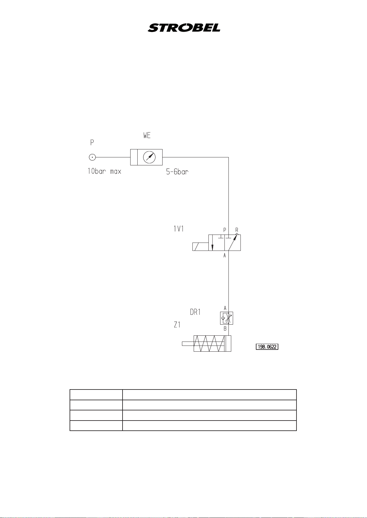
259.00.16en
Pneumatic circuit diagram cl. 142
DR1 One-way ow restrictor for lifting
MV1 3/2-solenoid-way valve
Z1 Cylinder for lifting (LÜ)
WE Service unit

259.10.16en
Pneumatic construction circuit diagram cl. 142
Wartungseinheit
service unit
Magnetventil
solenoid valve
198.0623
Lüftung
lifting
293.0469 1 Schalldämpfer R1/8
293.0470 1 Doppelnippel R1/8
193.0473 1100 PA-Schlauch Ø6x1
193.0478 3000 PA-Schlauch Ø8x1
193.0530 1 Dichtung R1/8
193.0658 1 Muffe R1/8
293.0731 1 Wartungseinheit
293.0841 1 L-Einschraubanschluss R1/8x8
293.0850 4 L-Einschraubanschluss R1/8x6
297.0170 1 Kupplungsstecker Ø8
298.0075 1 Spannzylinder
298.0077 1 Drosselrückschlagventil R1/8
298.0179 1 3/2 Wege-Magnetventil

Electric connection diagram cl. 141
Steck-Adapter EA 9044
Socket adapter EA 9044
258.21.27en
Digital display
R2
30,9kΩ
Widerstand
Resistor
Kippschalter
Flip switch
Batterie
Battery
R1
5kΩ lin.
Drehpotentiometer
Trimming potentiometer
398.0466


Und wir können noch mehr für Sie tun!
Unser Lieferprogramm bietet für jede Branche und
jegliche Anforderung genau die richtige Problemlösung.
And we can do a lot more for you!
Our range offers the correct problem solution for
every branch and for all requirements.
Für die Bekleidungsindustrie:
Ein- und ZweifadenHochleistungs-Saummaschinen
DoppelblindstichSaummaschinen
Zweifaden-Blindstich-
Stafermaschinen
Roll- und Flachpikiermaschinen
Pikier-Automat
und
weitere Spezial-Nähmaschinen
For the clothing
industry:
Single an two thread high
performance hemming
machines
Bluff edge hemming machines
Two thread blind stitch felling
machines
Roll and at padding machines
Automatic lapel padding
machine
and other special sewing
machines
Für die Schuhverarbeitung:
Einfaden-Überwendlichmaschinen mit und ohne
Differentialtransport
For the shoe industry:
Single-thread overseaming
machines with and without
differential feed
Für Kürschnereien
und Pelzkonfektion:
Pelzschnellnäher
Pelzpikiermaschine
Futterstafermaschine
For the fur industry:
Rapid fur sewing machines
Fur padding machine
Lining felling machine
Für Heimtextilien:
Ein- und ZweifadenBlindstichmaschinen
For the home textiles
industry:
Single and two thread
blind stitch machines
Für die Polsterverarbeitung:
Ein- und ZweifadenÜberwendlichmaschinen
Ein- und ZweifadenBlindstichmaschinen
For the upholstery
industry:
Single and two thread
overseaming machines
Single and two thread
blind stitch machines
Für die Konfektion
technischer Textilien:
Ein- und ZweifadenÜberwendlichmaschinen
For the processing
of technical textiles:
Single and two thread
overseaming machines

Noch Fragen?
Dann rufen Sie uns an, schreiben Sie uns oder
kommen Sie einfach bei uns vorbei.
Sie können jederzeit weitere Informationen über
unsere Produkte anfodern oder die StrobelNähmaschinen in unserem Ausstellungsraum live
erleben. Wir freuen uns auf Sie!
Any further questions?
Then phone, write or simply come and see us. You
can have further information about our products at
any time, or experience the Strobel machines live in
our show room. We’re looking forward to meeting you!
S pe z ia l ma s c hi n en Gm b H
Postfach 1242
82168 Puchheim
Siemensstraße 3
82178 Puchheim
DEUTSCHLAND
www.strobel.biz
Telefon: +49 89 80096-0
Telefax: +49 89 80096-190
 Loading...