

Strix Systems ACCESS-ONE-2, ACCESS-ONE-23, ACCESS-ONE-3, ACCESS-ONE-32, ACCESS-ONE-21 User Guide

Access / One® Network
The Inventory Function
This function provides you with an inventory view of your Access/One Network and
includes the following commands:
◗ Print Friendly Format
◗ Export to CSV
The inventory list is displayed in a tree structure that can be expanded (default) or
collapsed (show nodes only). The structure of the list consists of the Node ID, its
serial number and name, IP address and MAC address, the node type, the
technology it uses, and the current firmware version it is running. To compliment full
two-way authentication, the inventory list is synchronized and maintained between
all Strix devices. See also “Inventory or Auto Discovered” on page 63.
Manual additions (by node serial number)
Unreachable devices are listed here
Figure 86. Inventory List
5
Managing the Network 113

Access / One® Network
The inventory list allows you to manually add nodes, at your discretion. To add a
node to the inventory list, enter the node’s serial number in the Node ID field then
click on the Add button. Nodes that cannot be detected by the network will appear
in the Unreachable Devices frame.
5
The node’s alphanumeric serial number is case-sensitive, with all alpha
characters being upper case.
You also have the option of manually deleting nodes from the inventory list. To
delete a node, simply click on the X icon next to the node you want to delete. The
system will then prompt you for a confirmation. Click on the OK button to delete the
selected node, or click on the Cancel button to cancel your request.
Figure 87. Deleting a Node from the Inventory List
Print Friendly Format
This option converts the inventory list into a printer friendly format that can be
printed on standard letter size paper. After converting the inventory list, the system
prompts you for your printer’s destination. To initiate the printing process, click on
the Print button.
Figure 88. Printing the Inventory List
114 Managing the Network

Access / One® Network
Export to CSV
This option allows you to export the inventory file to a CSV (Comma Separated
Values) format that can be edited within a compatible spreadsheet application, such
as Microsoft Excel®.
Figure 89. CSV File
Importing the CSV File to an Excel Spreadsheet
When the CSV file is created, use the following procedure to import the file into an
Excel spreadsheet for editing.
5
1. Click in the header of the CSV file to make the CSV window active.
2. Press Ctrl+A to select all text in the CSV file.
3. Press Ctrl+C to copy the selected text to the clipboard.
4. Open a new Excel workbook, then press Ctrl+V to paste the CSV text into a
cell in the workbook.
5. Go to Data in the Excel menu bar and choose Tex t to Colu mn s... from the
pull-down list.
6. On the first page of the wizard in Excel select the Delimited option, then
click on the Next button.
7. On the second page of the wizard check the Comma check box to enable
the conversion with comma delimiters.
8. On the third and last page of the wizard, click on the Finish button to
convert the raw text into editable columns.
Managing the Network 115

Access / One® Network
The Monitor Function
This function provides you with tools that allow you to view your network’s
operation and performance, and includes the following commands:
◗ Too ls
• AP Monitor
• Network Connect Monitor
• Wireless Client Query
• Rogue Monitor
– Scan
– Ignore All
– Include All
Tools
5
Clicking on Tools in Manager/One’s toolbar generates a pull-down menu containing
all the commands that are available within the Monitor function.
AP Monitor
The AP Monitor provides a snapshot in table form of all active Client Connect
devices on a selected subnet.
Figure 90. AP Monitor (Default View)
116 Managing the Network

Access / One® Network
The table displayed in the AP Monitor window can be customized to show a defined
number of entries in the table, and the table can be sorted in either ascending or
descending order based on any selected column. For example, if you want to sort
the table by channel, click in the column header for Channel—the table is then
sorted according to the channels used by the Client Connects.
The target subnet can also be changed by selecting another subnet (as long as the
subnet exists in the pull-down list). In addition, the table offers instant access to the
assigned BSSID information for each node and you can log in to any node by simply
clicking on its IP address (all links are underlined).
Refresh
Sorted by ChannelSubnet
BSSID Information
Figure 91. An Overview of Monitor Tables (AP Monitor)
To define how the table is sorted, simply click in a column header to toggle between
ascending or descending for the data in that column to become the primary sort
criteria. The data in the AP Monitor table can be refreshed at any time.
Total Entries
5
Managing the Network 117

5
Access / One® Network
Network Connect Monitor
The Network Connect Monitor provides a snapshot in table form of all active
Network Connect devices on a selected subnet.
Figure 92. Network Connect Monitor
Although the displayed data is different, the organization of tables in all monitors is
the same. For information about how to define the sort criteria within the Network
Connect Monitor table, see Figure 91.
The only difference in the navigational content between the Network Connect
Monitor and the AP Monitor is the Network Connect Monitor also includes an
information button (i) in the top right corner of the window. Clicking on this button
generates the RSSI Legend pop-up window that provides a reference for the icons
displayed in the RSSI (dBm) column.
Figure 93. RSSI Legend
118 Managing the Network

Access / One® Network
Wireless Client Query
The Wireless Client Query Monitor provides a search tool that allows you to run a
query through the network and locate Wi-Fi clients based on the following search
criteria:
◗ Find a client based on a specific MAC address
◗ Find clients with an RSSI value of less than -85 dBm
Figure 94. Wireless Client Query Monitor
If you choose to search for a client based on its MAC address, the system prompts
you for the address. After entering the MAC address, click on the OK button to start
the search.
Figure 95. MAC Address Prompt
Although the displayed data is different, the organization of tables in all monitors is
the same. For information about how to define the sort criteria within the Wireless
Client Query Monitor table, see Figure 91. And similar to the Network Connect
Monitor, the Wireless Client Query Monitor also includes the information button (i)
in the top right corner of the window. Clicking on this button generates the RSSI
5
Legend pop-up window (see Figure 93).
Managing the Network 119

5
Access / One® Network
Rogue Monitor
The Rogue Monitor provides a snapshot in table form of all rogue devices detected
on a selected subnet.
Figure 96. Rogue Monitor
Although the displayed data is different, the organization of tables in all monitors is
the same. For information about how to define the sort criteria within the Rogue
Monitor table, see Figure 91. And similar to the Network Connect Monitor and the
Wireless Client Query Monitor, the Rogue Monitor also includes the information
button (i) in the top right corner of the window. Clicking on this button generates
the RSSI Legend pop-up window (see Figure 93).
Scan
Use this command if you want to initiate an active scan for rogue devices. Active
scans can take up to one minute to complete and network traffic will be disrupted
during the scanning process. Results from the scan are reported in the Rogue
Monitor table (see Figure 96).
Ignore All
Use this command to refresh the Rogue Monitor table with all detected rogue
devices ignored. All ignored devices are grayed out.
Include All
Use this command to refresh the Rogue Monitor table with all detected rogue
devices included.
120 Managing the Network

Access / One® Network
The Apply Configuration Function
This function is used to apply any configuration changes that have been made at
either the network or subnet level. When BLUE, click on this tab to propagate and
apply your changes to all nodes and wireless modules within your Access/One
Network or a specific subnet.
Apply Configuration
Figure 97. Apply Configuration
Important Notes About Apply Configuration
The following notes are important considerations when using the Apply
Configuration function.
For changes to be applied at the network or subnet level, you must
reboot the network after clicking on the Apply Configuration tab,
otherwise your changes will not be implemented.
The Apply Configuration function is not available when configuring
individual modules, because configuration changes at the module level
are applied automatically when you click on the Update button.
5
Managing the Network 121

Access / One® Network
5
It is recommended that you complete all of your configuration changes
before using the Apply Configuration command to propagate your
changes throughout the network. Once the Apply Configuration
command has been initiated, you cannot make any further changes
until the command cycle has been completed.
Enabling Communication Between Remote Subnets
Your Access/One Network can be configured to enable communication between
network servers on remote subnets, allowing you to manage subnets from any
network server on the network, regardless of its location. For example, remote
subnets in New York and Los Angeles can be configured and managed from the
same Manager/One interface.
It is strongly recommended that customers use an NTP (Network Time
Protocol) server to synchronize Access/One Network to one clock. This
will ensure that the system's internal Syslog time-stamping process is
maintained correctly. See also, “Enabling Windows 2000 Servers for
NTP Requests” on page 33. Without an NTP server (no universal clock),
each network server will use its own internal clock and stamp times
accordingly.
Example
Los Angeles and New York each have their own network:
◗ Los Angeles (LA): 172.20.0.0
◗ New York (NY): 192.152.1.0)
You want both networks to be managed by the same Manager/One interface, and
you can assume that a network server in Los Angeles (172.20.0.50) is the primary
server for the Access/One Network.
See also, “Starting a New Network” on page 32.
122 Managing the Network

Access / One® Network
Procedure
Configure a single remote network server for each subnet (NY: 192.162.1.22) on the
LA server. Within a few minutes, Strix’s mesh topology feature will cause all of the
remote subnets to automatically appear in each network server. Your Access/One
Network is now manageable from any of the network servers in the network.
Removing the NS to NS Feature
To remove the NS to NS communication feature, delete all of the remote server
entries on the LA server. When done, click on the Update button, then click on the
Apply Configuration tab and reboot the network (to apply your changes).
Managing Remote Subnets from Manager/One
In most cases, configuration of your Access/One Network will apply to all subnets to
maintain an homogeneous network. There are a few commands which can only be
applied at the subnet level. The following commands apply to the network level
only (regardless of what view is currently displayed):
◗ Load Firmware on Network
◗ The Apply Configuration Function
The following commands apply at the network or subnet level (depending on what
view is currently displayed):
◗ Reboot Network (network only)
◗ Reboot... (subnet / network)
The following commands are applicable only at the subnet level:
◗ Update Network Membership
◗ Update Node Names
5
Managing the Network 123

Access / One® Network
5
124 Managing the Network

Access / One® Network
Managing Subnets and Nodes
This chapter covers management tasks at the subnet and node levels—you can only
manage a subnet or node (you cannot configure subnets or nodes independent of
the network). If you are managing your Access/One Network at the network level, or
managing an individual module (for example, a wireless module or network server),
go to the relevant chapter:
◗ “Managing the Network” on page 65.
◗ “Managing Modules” on page 131.
The following graphic shows the subnet (subcloud) view in Manager/One’s main
window. The subnet view displays all nodes within the selected subnet and provides
interface features that are not available at the network level. All tasks in this chapter
are performed at the subnet or node levels.
Discovery Options
IP Address
Details Pane Subnet (Subcloud)
Figure 98. Subnet (Subcloud) View
Views
6
Managing Subnets and Nodes 125

Access / One® Network
Interface Features in the Subnet View
The interface features that are unique to the subnet view have already been
discussed in Chapter 4, The Manager/One Interface. They are listed here for your
convenience, and include:
◗ “A Choice of Layouts” on page 45.
◗ “The Details Pane” on page 56.
◗ “Inventory or Auto Discovered” on page 63.
The Manage Function
To avoid repetition, this section only addresses the management commands at the
subnet and node levels that are different from the equivalent commands at the
network level, or management commands that are unique to the subnet and node
levels. Therefore, the section headings included here are limited to the following
6
commands in the Manage function only:
◗ Commands (at the Subnet Level)
• Load Firmware...
– Subnet
– Network
• Reboot...
– Subnet
– Network
◗ Commands (at the Node Level)
• Update Node Names
• Update Network Membership
All other commands that are available at the subnet level but not listed here can be
found in Chapter 5, Managing the Network. You can also find them in the Table of
Contents and the Index.
126 Managing Subnets and Nodes

Access / One® Network
Commands (at the Subnet Level)
Load Firmware...
This command allows you to load a new firmware image to each of the modules
contained in all network nodes within your Access/One Network or to a specific
subnet. However, before you can load a new image, your FTP server parameters
must be established correctly to let Manager/One know where to locate the new
image (BIN) file.
To establish the correct FTP parameters and load new firmware at the network or
subnet levels, go to “Updating the Firmware” on page 35.
Subnet
Choose this option to load new firmware to all devices within the selected subnet.
Network
Choose this option to load new firmware to all subnets and devices within your
entire Access/One Network.
Reboot...
This command reboots each module in all nodes within your Access/One Network
or a selected subnet. Rebooting is required when configuration changes are made or
a new firmware image is loaded. To monitor the progress of the reboot operation,
the network server generates the request in stages. When each module reports
receiving the reboot command and successfully reboots, the network server
performs a final self-reboot. You can monitor reboot progress reports with the View
Action Status command or from the Command Progress pane.
Success
Figure 99. Command Progress Pane
6
Managing Subnets and Nodes 127

Access / One® Network
Whenever you initiate the Reboot... command, the system warns you that this action
will affect multiple devices on the network (or subnet) and asks you to confirm the
request. If you want to proceed, click on the OK button to initiate the reboot
process, otherwise click on the Cancel button to abort the command.
See also, “Important Note About Rebooting” on page 4.
Subnet
Choose this option to reboot the selected subnet.
Network
Choose this option to reboot your entire Access/One Network.
Commands (at the Node Level)
Update Node Names
6
The ability to assign names to your nodes is provided as a convenience to users who
want their nodes to have meaningful names (for example, based on the node’s
location).
Node Name
Figure 100. Node Name (Flat View)
In Manager/One, the node name appears below the node in an editable text field.
You can assign any name with up to 15 alphanumeric characters, but the name must
be unique within your Access/One Network. If you attempt to enter a name that
already exists (a duplicate name), Manager/One will prompt you for a new name.
Name changes do not require a reboot, but may take between 10 and 15 seconds
before the change is reported. Refresh your browser window frequently to ensure
that the latest information is displayed.
128 Managing Subnets and Nodes

Access / One® Network
To change a name, simply enter a new name in the text field below the node and
select the Update Node Names command. When prompted, click on the OK button
to apply your change.
Update Network Membership
The subnet (subcloud) displays all of the nodes residing in the network. Nodes
already assigned to the network (members) are GREY in color and the check box
below the node is checked.
Figure 101. Network Membership
You can add or remove nodes from the network by checking or unchecking the
check box below the node, then selecting the Update Network Membership
command. This action forces a reboot of the nodes which have changed their
membership status (nodes not admitted to a network, other than the default, will not
bridge user traffic).
IWS nodes that are BLUE do not have a check mark in the check box,
and although they are currently not assigned to the network, they can
be admitted (become members). All nodes admitted to the network will
be rebooted. Nodes that are RED also do not have a check mark in the
check box, but these nodes are unavailable and cannot be assigned to
the network.
6
Managing Subnets and Nodes 129

Use this Space for Your Notes
Access / One® Network
6
130 Managing Subnets and Nodes

Access / One® Network
Managing Modules
This chapter covers management and configuration tasks at the individual module
level (for example, wireless modules or network servers). It is generally sufficient to
configure your Access/One Network as a whole without configuring specific
modules. If you are managing the network, a subnet or node, go to the relevant
chapter:
◗ “Managing the Network” on page 65.
◗ “Managing Subnets and Nodes” on page 125.
When a module is configured, the module’s manually configured parameters will
always override the global network parameters that are configured or defaulted at
the network level. It is presumed that if a module is manually configured, then the
module’s values take precedence over global network values.
Manger/One at the Module Level
When you drill down to the module level in Manager/One you will notice that the
function tabs and available commands change, depending on what type of module
you have selected (wireless module or network server). For example, If you are
logged in to a wireless module, Manager/One presents you with a Rogue Devices
function and Wi-Fi commands under the Configure function—none of these options
being available if you are logged in to a network server (they are not required for
network servers).
Also, and regardless of what type of module you are logged in to, the Apply
Configuration tab is not available at the module level. The Apply Configuration tab
is only applicable at the network level where you need to propagate your
configuration changes across the entire network.
To avoid repetition, this chapter only addresses the commands at the module level
that are different from the equivalent commands at the network level, or commands
that are unique to individual modules. For your convenience, cross-references are
included that will take you to the corresponding commands at the network level.
7
Managing Modules 131

Access / One® Network
When you initiate a command at the module level, the configuration pages that are
displayed contain the configuration settings that are currently applied to the selected
module only (not the network or any other module).
In most cases, the only difference between a configuration window
generated at the network level and the same window generated at the
module level is the inclusion of pre-configured module data (if any) in
the fields contained within the window.
The Manage Function
This function provides you with the tools you need to manage individual modules
and includes the following commands:
◗ Actions
• Factory Defaults
• Load Firmware/Configuration
• Page Device
• Reboot
7
132 Managing Modules

Access / One® Network
Actions
This area of Manger/One applies to all modules (wireless modules and network
servers) and contains commands that allow you to establish factory default settings,
load firmware and/or configuration files, and page or reboot the module.
Factory Defaults
This command allows you to set the module’s configuration settings to their factory
default state or remove the subnet and/or network configuration parameters from the
module.
Figure 102. Device Configuration Window
Make your selection(s) from the available options:
◗ Set Device Configuration To Factory Defaults
Enable this option to reset the module to its factory default state.
◗ Remove Sub-cloud Configuration From Device
Enable this option to remove any configuration settings that were applied to
the module at the subnet level.
◗ Remove Cloud Configuration From Device
Enable this option to remove any configuration settings that were applied to
the module at the network level.
After making your selections, click on the Factory Default button to apply your
changes, then click on the Reboot button to reboot the module.
Managing Modules 133
7

Access / One® Network
Load Firmware/Configuration
This command allows you to load a new firmware image and /or configuration file
to the module, restore a previous version (or backup file), or upload a backup
firmware image and /or configuration file. The following graphic shows the Load
Firmware/Configuration window with its options set for uploading a backup
configuration file.
7
Figure 103. Loading a New Firmware Image or Configuration File
Go to “Firmware Updates” on page 143 and establish the FTP server parameters to
inform Manager/One where to locate the new firmware image or configuration file,
and which file to use. The following options are available with this command:
◗ Action Type
Choose Download, Restore Previous Version, or Upload.
◗ File Version
Define the file version, either Current or Backup (only available if you are
uploading a file).
◗ File Type
Define the file type, either Image or Configuration.
Click on the Download Now, Restore Now, or Upload Now button (depending on
which action you defined) to execute the command, then click on the Reboot
button to reboot the module.
134 Managing Modules

Access / One® Network
Page Device
This command allows you to page the module (device) that you are currently logged
in to.
Figure 104. Paging a Device
To page the module, simply click on the Page Device button. When an IWS (Indoor
Wireless System) module is paged, the module’s LED blinks between GREEN and
RED, indicating that communication with the module is successful. The module will
be paged until you click on the Disable Page button.
Reboot
This command allows you to reboot the module.
Figure 105. Rebooting a Module
Click on the Reboot button to reboot the module, or click on the Cancel button to
cancel the request.
7
Managing Modules 135

Access / One® Network
The Configure Function
This function provides you with the tools you need to configure individual modules
and includes the following commands:
◗ System
• User Login
• Network Management
– General
– SNMP
– Trusted IP Addresses
• TCP/IP Settings
• Priority/One - Class of Service
• Radius Accounting
• Syslog
7
• Date and Time
• Operating Environment
• Firmware Updates
◗ Wi-Fi (Wireless Modules Only)
• Radio Parameters
• Client Connect
• Network Connect
• Rogue Scan
System
This area of Manger/One applies to all modules (wireless modules and network
servers) and contains commands that allow you to configure the module’s systemlevel parameters. Any configuration parameters that you apply to the module will
supersede the equivalent system-level parameters that were applied at the network
level and propagated to the module from the Apply Configuration tab.
136 Managing Modules

Access / One® Network
User Login
This command allows you to establish the identity of this module, define its physical
location within the environment based on latitude, longitude and elevation, and set
up the module’s login parameters (username and password).
Figure 106. Module Identity and User Management (Login) Parameters
The following options are available with this command:
◗ Module Name
Edit the existing name or enter a new name for this module. If no name is
defined for the module, the system automatically sets the module’s factory
default serial number as the name.
◗ Network Name
This field (not editable) shows the name of the network that this module is
associated with. If you need to change the network association for this
module, go to “Update Network Membership” on page 129.
◗ Latitude
This field allows you to define the specific latitude for where this module is
located (more relevant to OWS modules where physical location and
environment can be extreme). This setting must be within the range of -90
degrees/minutes to +90 degrees/minutes. The default is +0.000000.
7
Managing Modules 137

Access / One® Network
◗ Longitude
This field allows you to define the specific longitude for where this module is
located (more relevant to OWS modules where physical location and
environment can be extreme). This setting must be within the range of -180
degrees/minutes to +180 degrees/minutes. The default is +0.000000.
◗ Elevation
This field allows you to define the specific elevation (in feet) for where this
module is located (more relevant to OWS modules where physical location
and environment can be extreme). The default is +0 feet (sea level).
◗ User name
Select a user name from the pull-down list (Admin or Guest). Any changes
you make to the password in the following field will affect logins to this
module for the selected user name only.
◗ Password
Enter a password (between 5 and 32 characters). All passwords are casesensitive. Any change you make to the password will affect logins for this
module only.
7
◗ Confirm Password
Re-enter the password to confirm that you typed it correctly.
The default for the user name and the password for all modules
within your Access/One Network is Admin (with a capitalized A)
for both. We strongly recommend that you change the default
password immediately after your initial login.
◗ Password Encryption
Check this box if you want Access/One Network to encrypt your password for
additional security.
When finished, click on the Update button to update this page and apply your
changes, then click on the Reboot button to reboot the module. If necessary, you
can click on the Refresh button in the toolbar to reset all parameters on this page to
their original values.
138 Managing Modules

Access / One® Network
Network Management
This command generates three sub-commands (General, SNMP, and Trusted IP
Addresses) that allow you to define parameters for how the module is managed
within your Access/One Network. For the most part, these commands are the same
as their corresponding commands at the network level (with some minor exceptions
that are documented here).
General
Unless you are logged in to a network server, this command is the same as its
corresponding command at the network level. In this case, go to “General” on
page 73 to configure all options under this command. If you are logged in to a
network server, the window generated by this command includes an additional
option called Client Connect Privacy Tags.
Figure 107. Client Connect Privacy Tags
◗ Client Connect Privacy Tags
Check the box for Preserve Tags on Egress to LAN if you want this module to
preserve any client connect privacy tags that have been assigned to your
Access/One Network. See also, “Client Connect” on page 98.
Managing Modules 139
7

Access / One® Network
When finished, click on the Update button to update this page and apply your
changes, then click on the Reboot button to reboot the module. If necessary, you
can click on the Refresh button in the toolbar to reset all parameters on this page to
their original values.
SNMP
The only difference between the SNMP configuration window generated at the
module level and the corresponding window at the network level is the addition of
the Description and Name identifier fields, specific to the module. For all other
SNMP configuration options, go to “SNMP” on page 75.
7
Figure 108. Module Description and Name
The Description field provides a description of the module and is not editable. If
desired, you can enter a new name for the module in the Name field.
When finished, click on the Update button to update this page and apply your
changes, then click on the Reboot button to reboot the module. If necessary, you
can click on the Refresh button in the toolbar to reset all parameters on this page to
their original values.
140 Managing Modules

Access / One® Network
Trusted IP Addresses
This command is the same as its corresponding command at the network level. To
configure these options for the module, go to “Trusted IP Addresses” on page 141.
When finished, click on the Update button to update this page and apply your
changes, then click on the Reboot button to reboot the module. If necessary, you
can click on the Refresh button in the toolbar to reset all parameters on this page to
their original values.
TCP/IP Settings
This command is similar to the TCP/IP Settings command used at the network level,
with the addition of the IP Settings option. For all other TCP/IP configuration
options, go to “TCP/IP Settings” on page 78.
Figure 109. TCP/IP Settings (Module Level)
◗ IP Settings
Choose whether you want the system to use DHCP to obtain the module’s IP
address automatically (default), or use a pre-configured static IP address. If
you choose the latter option, you must enter a valid IP address and Subnet
Mask in the appropriate fields.
Managing Modules 141
7

Access / One® Network
When finished, click on the Update button to update this page and apply your
changes, then click on the Reboot button to reboot the module. If necessary, you
can click on the Refresh button in the toolbar to reset all parameters on this page to
their original values.
Priority/One - Class of Service
This command is the same as its corresponding command at the network level. To
configure these options for the module, go to “Priority/One - Class of Service” on
page 81.
When finished, click on the Update button to update this page and apply your
changes, then click on the Reboot button to reboot the module. If necessary, you
can click on the Refresh button in the toolbar to reset all parameters on this page to
their original values.
Radius Accounting
7
This command is the same as its corresponding command at the network level. To
configure these options for the module, go to “Radius Accounting” on page 84.
When finished, click on the Update button to update this page and apply your
changes, then click on the Reboot button to reboot the module. If necessary, you
can click on the Refresh button in the toolbar to reset all parameters on this page to
their original values.
Syslog
This command is the same as its corresponding command at the network level. To
configure these options for the module, go to “Syslog” on page 85.
When finished, click on the Update button to update this page and apply your
changes, then click on the Reboot button to reboot the module. If necessary, you
can click on the Refresh button in the toolbar to reset all parameters on this page to
their original values.
142 Managing Modules

Access / One® Network
Date and Time
This command is the same as its corresponding command at the network level. To
configure these options for the module, go to “Date and Time” on page 88.
When finished, click on the Update button to update this page and apply your
changes, then click on the Reboot button to reboot the module. If necessary, you
can click on the Refresh button in the toolbar to reset all parameters on this page to
their original values.
Operating Environment
This command is the same as its corresponding command at the network level. To
configure these options for the module, go to “Operating Environment” on page 91.
When finished, click on the Update button to update this page and apply your
changes, then click on the Reboot button to reboot the module. If necessary, you
can click on the Refresh button in the toolbar to reset all parameters on this page to
their original values.
Firmware Updates
This option is similar to the Firmware Updates command used at the network level,
but without the FTP Update Aggressiveness options, and with the addition of the File
Name field (for defining a new configuration file). For all other Firmware Updates
configuration options, go to “Firmware Updates” on page 91.
Figure 110. Setting Up the FTP Server (Module Level)
7
Managing Modules 143

Access / One® Network
◗ File Name
If you are calling a file other than accessone.bin or accessone_m.bin for this
module, enter the name of the file in this field.
When finished, click on the Update button to update this page and apply your
changes, then click on the Reboot button to reboot the module. If necessary, you
can click on the Refresh button in the toolbar to reset all parameters on this page to
their original values.
Wi-Fi
This area of Manger/One applies only to wireless modules (not network servers) and
contains commands that allow you to configure the module’s Wi-Fi parameters. Any
configuration parameters that you apply to the module will supersede the equivalent
system-level parameters that were applied at the network level and propagated to
the module from the Apply Configuration tab.
7
The menu structure under the Wi-Fi option is slightly different, depending on
whether you are logged in to a single band wireless module or a dual band wireless
module. The differences between the menus are as follows:
◗ Wi-Fi (single band radio)
• Radio Parameters
• Client Connect
• Network Connect
• Rogue Scan
◗ Wi-Fi (dual band radio)
• 802.11a Radio
– Parame te rs
– Client Connect
– Network Connect
– Rogue Scan
• 802.11g Radio
– Parame te rs
– Client Connect
– Network Connect
– Rogue Scan
Figure 111. Single and Dual Band Wi-Fi Menu Structure
144 Managing Modules

Access / One® Network
Radio Parameters
This command is similar to the Radio Parameters command used at the network
level, but with fields that are relevant only to the selected wireless module. To avoid
confusion, the page generated by this command will be documented here in full. All
changes made to this page will be applied only to the module you are currently
logged in to (not to the entire network).
The following graphic shows an example of the Radio Parameters page for an
802.11a wireless module.
Figure 112. Radio Parameters (Module Level)
Managing Modules 145
7

The following options are available with this command:
◗ Active Country Code
This field (not editable) shows the currently active country code.
◗ Config Country Code
This field is not editable because this model of your Access/One Network
applies only to the United States (which is the only country code available).
◗ Operating Mode
This option allows you to select the operating mode (either Client Connect or
Network Connect) manually, or choose Automatic Selection if you want the
module to select its operating mode automatically.
◗ Wireless Mode
This option allows you to select the wireless mode for this module. The
following modes are available:
• 802.11a
Access / One® Network
7
– 802.11a: This is the default standard 802.11a wireless mode.
– 802.11a Turbo: This configures the module to operate in Turbo
mode, allowing it to operate with data rates at speeds up to 108
Mbps. This translates to nearly double the throughput, but all user
devices must be capable of running the 802.11a Turbo mode and be
configured for it. Turbo mode is not an industry standard and so not
all 802.11a user devices support this feature.
• 802.11g
– 802.11g: This is the default standard 802.11g wireless mode.
– 802.11g Only: This mode restricts the module to the 802.11g
wireless mode only and does not allow 802.11b compatibility.
146 Managing Modules

Access / One® Network
– 802.11g Super: This mode provides support for the Atheros Super G
FastFrames throughput enhancement technology, with data rates up
to 108Mbps and compatible with the 802.11g (54 Mbps) wireless
technology. This translates to nearly double the throughput, but there
are some limitations, including:
– Only one operating channel is supported.
– All user devices must also be capable of running 802.11g Super
G and be configured for it. Super G is not an industry standard
and so not all 802.11g user devices support this feature.
– 802.11b Only (No 802.11g): This mode restricts the module to the
802.11b mode only and does not allow 802.11g compatibility.
◗ Allow Association Over Long Distances
This option allows you to set a distance (up to 25 miles) for wireless
associations over long distances (the default is 3 miles).
◗ WLAN Radio Client Limits
This option allows you to restrict the number of clients that can associate with
the module. The default is 128. Setting this field to 0 (zero) prevents all client
access to the module.
◗ Frequency/Rate/Power
These options define the operating frequency, data rate and transmit power
for the module. The fields for these options include:
• Active Radio Frequency
This field displays the active radio frequency that this module is currently
using.
• Radio Frequency
This option allows you to manually change the operating frequency from
the frequencies available in the pull-down list. Alternatively, you can
choose the SmartSelect option which will instruct the system to select the
best frequency automatically.
7
Managing Modules 147

Access / One® Network
• Data Rate
This option allows you to select the data rate for the wireless module
from the choices available in the pull-down list. All data rates are
specified in Mbps (Megabits per second). You can choose a specific data
rate from the pull-down list, or choose the Best option, which will
instruct the system to select the best data rate for the wireless module
automatically. The available data rates are determined by which type of
wireless module (802.11a or 802.11g) you are logged in to.
• Transmit Power
This option allows you to select the level of transmit power for the
wireless module from the choices available in the pull-down list (either
Full, Half, Quarter, One Eighth, or Minimum). You can decrease the
transmit power to decrease the range of the module. The default value for
this parameter is Full (maximum power).
Depending on the selected antenna(s) for your application—especially
relevant to the OWS—it may be necessary to configure the transmit
power. It is the installer's responsibility to ensure that the transmit power
7
is set correctly for the chosen antenna(s). Operation in a manner other
than is represented in this document is a violation of FCC rules.
For a complete listing of the maximum power settings allowed for
antennas, go to “Power Settings for Antennas” on page 165.
148 Managing Modules

Access / One® Network
◗ 802.11a Channel Selector
These options extend the range of 802.11a wireless capability by allowing
you to select 802.11a wireless channels. Check the corresponding box to
enable an 802.11a channel of your choice.
◗ 802.11g Channel Selector
These options extend the range of 802.11g wireless capability by allowing
you to select 802.11g wireless channels. Check the corresponding box to
enable an 802.11g channel of your choice.
◗ 802.11g (only)
These options allow you to set up how your 802.11g wireless module
performs (not applicable to 802.11a radios). Options that are specific to
802.11g radios include:
• Protection Mode
This is a mechanism to let 802.11g devices know when they should use
modulation techniques to communicate with another 802.11b device,
especially in wireless networks where there is a mixed environment that
has 802.11g and 802.11b clients (and the clients are hidden from each
other. The protection mode options are:
– None
This assumes there are no wireless stations using 802.11b (11 Mbps)
technology. If operating in a mixed 802.11b/g network with minimal
802.11b traffic, choose this option to ensure the best performance for
your 802.11g stations.
– Always
Protects 802.11b traffic from colliding with 802.11g traffic. This
mode is not recommended, especially if only a few wireless stations
are operating with 802.11b. Only use this mode in environments
with heavy 802.11b traffic or where there is interference.
7
Managing Modules 149

Access / One® Network
– Auto
This is the default mode and will enable protection for 802.11g
stations if your Access/One Network finds an 802.11b client. In this
mode, if the 802.11b client leaves the network the protection mode
will revert to None automatically.
• Protection Rate
Sets the data rate at which the RTS-CTS (Request-to-Send and Clear-toSend) packets are sent (either 1 Mbps, 2 Mbps, 5.5 Mbps, or 11 Mbps).
The 11 Mbps data rate is the default.
• Protection Type
This option is only relevant when the Protection Mode is on. The options
here are CTS-only or RTS-CTS. With CTS-only, the client is not required
to send an RTS (Request-to-Send) to the AP. As long as the client receives
a CTS (Clear-to-Send) frame from the AP then the client is free to send
data. With the RTS-CTS option enabled, the client is required to send an
RTS to the AP and wait for a CTS from the AP before it can send data (this
option creates additional overhead and can cause performance
7
degradation). The default is CTS-only.
• Short Slot Time
802.11g defines the long slot time as 20 microseconds and a short slot
time as 9 microseconds. 802.11b only supports the long slot time of 20
microseconds. In an environment with 802.11g devices only, this option
(Short Slot Time) must be enabled for better performance—giving
precedence to 802.11g traffic. Only disable this option in mixed
(802.11b and 802.11g) environments. The default is enabled.
• Short Slot Preamble
Short slot preamble improves network efficiency by reducing the
preamble from 128 bits to 56 bits. 802.11g is required to support both
short and long preambles (802.11b support for a short preamble is
optional). If this option is enabled, any 802.11b clients associated with
the network must support a short preamble. The default for this option is
enabled.
150 Managing Modules

Access / One® Network
◗ Advanced Settings
These advanced settings are preconfigured with the optimum settings for your
wireless module. Changing any of these settings may negatively affect the
module’s performance. For best results, leave these settings at their default
values.
• Beacon Interval
The beacon is a uniframe system packet broadcast by the AP to keep the
module synchronized. Enter a value in this field between 20 and 1000
(milliseconds) that specifies the beacon interval. The default value is 100.
• Delivery Traffic Indication Message (DTIM Period)
Enter a value between 1 and 255 that specifies the Delivery Traffic
Indication Message (DTIM). Increasing this interval allows the station to
sleep for longer periods of time resulting in power savings (in exchange
for some degradation in performance). The default value is 1.
• Fragment Length
Enter a value between 256 and 2346. This setting determines the size of
the wireless frame. Wireless frames are reassembled by the wireless
module before being forwarded to the Ethernet port, but only if the frame
is smaller than the Ethernet MTU (1536 bytes). The default value is 2346.
• RTS/CTS Threshold
This is a value that determines at what frame length the RTS-CTS function
is triggered. By default, the threshold is set at its highest value. A lower
value means that the RTS-CTS function is triggered for smaller frame
lengths. A lower threshold value may be necessary in environments with
excessive signal noise or hidden nodes, but may result in some
performance degradation. Enter a value between 256 and 2346 to specify
the RTS/CTS threshold. The default value is 2346.
When finished, click on the Update button to update this page and apply your
changes, then click on the Reboot button to reboot the module. If necessary, you
can click on the Refresh button in the toolbar to reset all parameters on this page to
their original values.
7
Managing Modules 151

Access / One® Network
Client Connect
This command is similar to its corresponding command at the network level. The
only difference between the configuration windows is that the Client Connect
Privacy Tags option is not displayed at the module level. To configure your Client
Connect options for a wireless module, go to “Client Connect” on page 98.
7
Figure 113. Client Connect Configuration Window
When finished, click on the Update button to update this page and apply your
changes, then click on the Reboot button to reboot the module. If necessary, you
can click on the Refresh button in the toolbar to reset all parameters on this page to
their original values.
152 Managing Modules

Access / One® Network
Network Connect
This command is similar to its corresponding command at the network level, with
the addition of the Target MAC Address and Ignore RTD options. For all other
configuration options, go to “Network Connect” on page 106.
Figure 114. Network Connect Configuration Window
◗ Target MAC Address
Enter the MAC address for the wireless module to enable peer-to-peer
connectivity based on the module’s MAC address. You only need to complete
the MAC address (the first three fields are inputted automatically).
◗ Ignore RTD
Check this box to instruct the system to ignore the RTD (Round Trip Delay),
which ensures that the backhaul will stay connected to an AP even if the RTD
is zero. When RTD from a Client Connect is set to 0 (zero) a Network
Connect will drop its wireless connection to that Client Connect and scan for
a peer with a non zero RTD (that can ping the gateway). Ignoring the RTD
will keep the link up to that peer regardless, and eliminate self-healing. The
default is to ignore the RTD (enabled).
Managing Modules 153
7

Access / One® Network
When finished, click on the Update button to update this page and apply your
changes, then click on the Reboot button to reboot the module. If necessary, you
can click on the Refresh button in the toolbar to reset all parameters on this page to
their original values.
Rogue Scan
This option allows you to define which channels are scanned for rogue devices by
the defined country code (similar to its corresponding command at the network
level, but without the option for defining a rogue list refresh period). To configure
rogue scan channel selections for the module, go to “Rogue Scan” on page 111.
When finished, click on the Update button to update this page and apply your
changes, then click on the Reboot button to reboot the module. If necessary, you
can click on the Refresh button in the toolbar to reset all parameters on this page to
their original values.
7
154 Managing Modules

Access / One® Network
The Monitor Function
This function provides you with the tools you need to monitor the performance of
individual modules and includes the following commands:
◗ Reports
• Radio Statistics
Applicable to wireless modules only.
• Wireless Neighbors
Applicable to wireless modules only.
• Wireless Client Monitor
Applicable to wireless Client Connect modules only.
• SSIDs / VLANs List
Applicable to wireless Client Connect modules only.
• Device Information
Applicable to all wireless modules and network servers.
7
Managing Modules 155

Access / One® Network
Reports
This area of Manger/One applies to all wireless modules and network servers and
contains commands that allow you to monitor the performance of individual
modules within your Access/One Network. It should be noted that the menu
structure under the Reports option is slightly different, depending on whether you
are logged in to a single band wireless module or a dual band wireless module. The
differences between the menus are as follows:
7
◗ Reports (single band radio)
• Radio Statistics
• Wireless Neighbors
• Wireless Client Monitor
• SSIDs / VLANs List
• Device Information
Figure 115. Single and Dual Band Reports Menu Structure
The Radio Statistics, Statistics (dual band radios only) and Wireless Neighbors
commands are only available when logged in to a wireless module—not a network
◗ Reports (dual band radio)
• 802.11a Radio
– Statistics
– Wireless Neighbors
– Wireless Client Monitor
– SSIDs / VLANs List
• 802.11g Radio
– Statistics
– Wireless Neighbors
– Wireless Client Monitor
– SSIDs / VLANs List
• Device Information
server.
The Wireless Client Monitor and SSIDs / VLANs List commands are only available
when logged in to a wireless module that is configured as a Client Connect—not a
Network Connect or network server.
The Device Information command is available for all wireless modules, including
network servers.
156 Managing Modules

Access / One® Network
Radio Statistics
This command is used to generate a statistical performance report relative to the
selected wireless module. You can Clear the data or Recalculate the data that is
displayed on this page, as required.
Clearing the data resets all values to zero. If you recalculate (refresh) the data, the
wireless module is polled and current operating data is displayed. Clicking on the
Refresh button in the toolbar has the same effect as recalculating the data.
The following graphic shows an example of the Radio Statistics report for an
802.11a wireless module operating in the 5 GHz band with a data rate of 54 Mbps.
Recalculate
Clear
Figure 116. Radio Statistics
Managing Modules 157
7
Access / One® Network
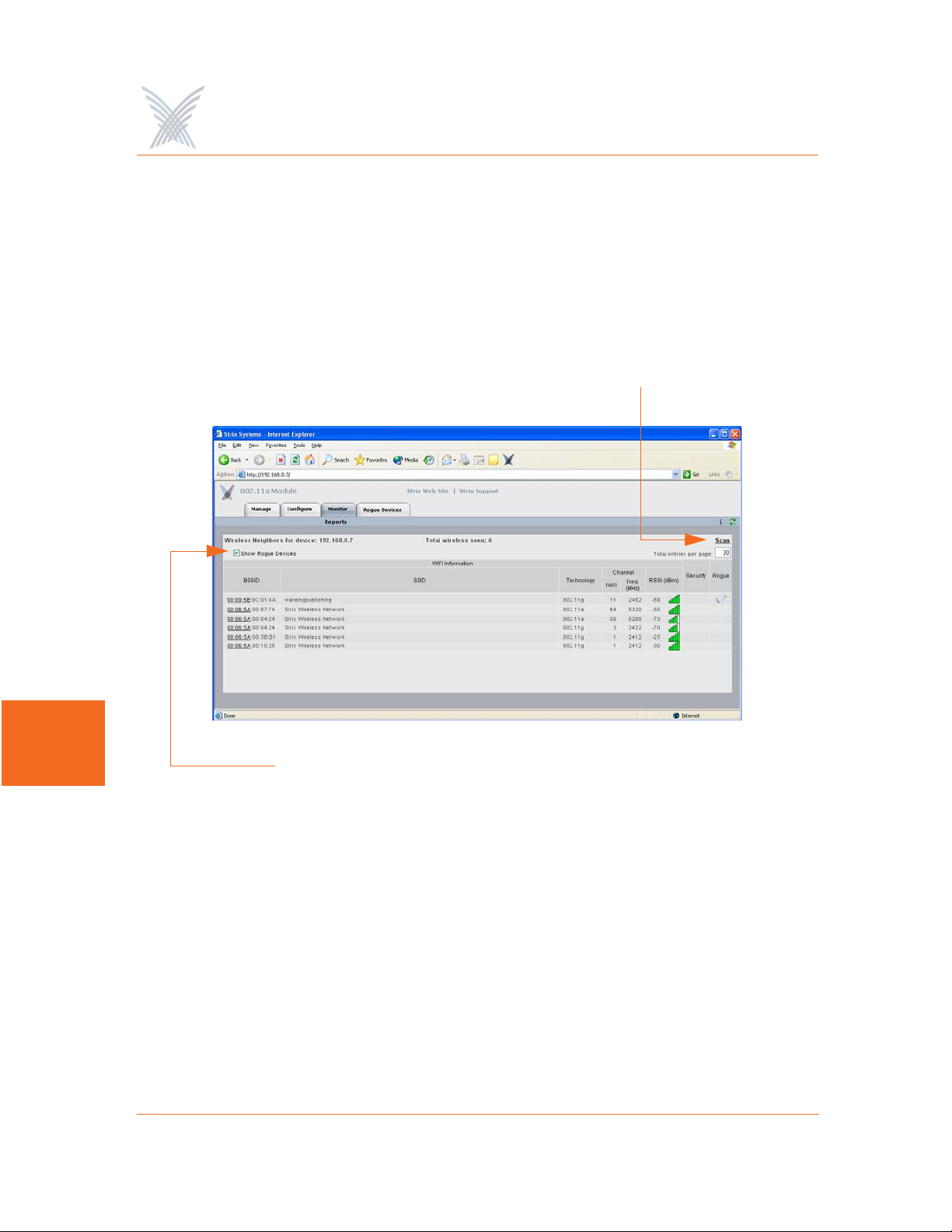
Wireless Neighbors
This command is used to generate a report that shows all wireless neighbors for the
module, including any rogue devices (if enabled). To generate the report, click on
the Scan button—it may take up to one minute to complete the scan for wireless
neighbors and return the results. To include rogue devices in the scan, simply check
the Show Rogue Devices check box. The default is to include rogue devices.
Scan for Neighbors
7
Show Rogue Devices
Figure 117. Wireless Neighbors
The table displayed in the Wireless Neighbors window can be customized to show a
defined number of entries in the table, and the table can be sorted in either
ascending or descending order based on any selected column. For example, if you
want to sort the table by wireless technology, click in the column header for
Technology—the table is then sorted according to the wireless technology used by
each wireless neighbor. The default is to have the table sorted by BSSID in
descending order. You can refresh the data on this page by clicking on the Refresh
button in the toolbar. In addition, you can view the RSSI legend by clicking on the
Information button (i) in the toolbar.
158 Managing Modules
Access / One® Network
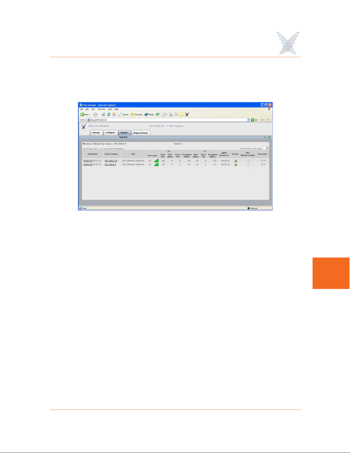
Wireless Client Monitor
This command is used to generate a report that shows all Client Connects that are
currently associated with the module you are logged in to.
Figure 118. Wireless Client Monitor
The table displayed in the Wireless Client Monitor window can be customized to
show a defined number of entries in the table, and the table can be sorted in either
ascending or descending order based on any selected column. For example, if you
want to sort the table by the IP address of each client, click in the column header for
Client IP Address—the table is then sorted according to the IP address designated for
each client. The default is to have the table sorted by Client BSSID in descending
order. You can refresh the data on this page by clicking on the Refresh button in the
toolbar. In addition, you can view the RSSI legend by clicking on the Information
button (i) in the toolbar.
If you know the username and password, you can also log in to a client by clicking
on its IP address, or you can click on a client’s BSSID and view the BSSID
information associated with the client (see also, “AP Monitor” on page 116).
The far right column offers a convenient tool for disconnecting from any of the
clients in the table—simply click on the disconnect icon in this column to
disconnect from the associated client.
7
Managing Modules 159

Access / One® Network
SSIDs / VLANs List
This command is used to generate a report that shows all SSIDs and VLANs currently
associated with the module you are logged in to.
Figure 119. SSID / VLANs List
7
The table displayed in the SSIDs / VLANs List window can be sorted in either
ascending or descending order based on any selected column. For example, if you
want to sort the table by the priority assigned to each VLAN, click in the column
header for Priority—the table is then sorted according to the VLAN priority. The
default is to have the table sorted by VLAN in descending order.
You can refresh the data on this page by clicking on the Refresh button in the
toolbar. In addition, you can view the Wi-Fi legend by clicking on the Information
button (i) in the toolbar. The legend shows the meaning of the icon displayed in the
Type column.
Client Connect (Virtual/Strix) is the system topology that enables your Access/One
Network to support and provide access to client devices using most wireless
technologies, including 802.11a or 802.11g. With Client Connect you can
customize each network node to support the wireless technologies you need in the
locations you need them. Any mix of these technologies can be supported within a
single node or across the entire Access/One Network. To understand how SSIDs and
VLANs are assigned to clients, go to “Client Connect” on page 152.
160 Managing Modules

Access / One® Network
Device Information
This command is used to generate a report that shows information about the module
you are logged in to. Figure 120 shows the Device Information window generated
while logged in to an 802.11a wireless module. Unlike most monitoring windows,
pages generated by the Device Information command are not configurable.
Figure 120. Device Information (802.11a Module)
Figure 121 shows the Device Information window generated while logged in to a
network server module.
Figure 121. Device Information (Network Server)
7
Managing Modules 161
Access / One® Network
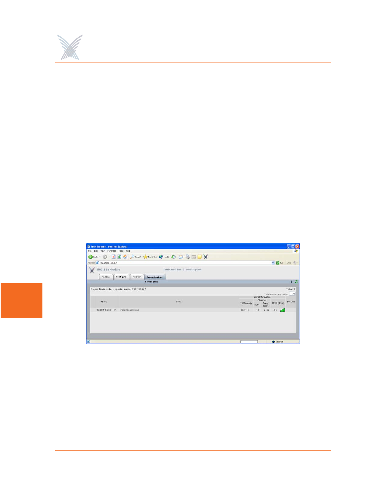
The Rogue Devices Function
This function provides you with a rogue scanning tool that allows you to scan for all
rogue devices. The scanning tool offered here is similar to the Rogue Monitor tool
provided at the network level, but applies only to rogue devices detected by the
wireless module that you are logged in to.
Commands
This area of Manger/One applies to wireless modules only.
Scan
Use this command if you want to initiate an active scan for rogue devices. Active
scans can take up to one minute to complete and traffic to and from the module will
be disrupted during the scanning process. Results from the scan are reported in the
Rogue Monitor table.
7
Figure 122. Rogue Monitor Table
The table displayed in the Rogue Monitor table can be sorted in either ascending or
descending order based on any selected column. For example, if you want to sort
the table by technology, click in the column header for Technology—the table is
then sorted according to the wireless technology used by the rogue device. The
default is to have the table sorted by BSSID in descending order.
162 Managing Modules

Access / One® Network
You can refresh the data on this page by clicking on the Refresh button in the
toolbar. In addition, you can view the RSSI legend by clicking on the Information
button (i) in the toolbar.
In addition, you can click on a rogue’s BSSID and view the BSSID information
associated with the rogue device. For example:
Figure 123. BSSID Information for Rogue Device
For more information about rogue devices, go to:
◗ “Detecting Rogue Devices” on page 13.
◗ “Rogue Scan” on page 111.
◗ “Rogue Monitor” on page 120.
◗ “Rogue Scan” on page 154.
7
Managing Modules 163

Use this Space for Your Notes
Access / One® Network
7
164 Managing Modules

Access / One® Network
Power Settings for Antennas
The following tables show the maximum power settings based on the type of
antenna
Channels for IEEE 802.11b/g
1
being used and the wireless band.
12 dBi Omni Antenna (2.4 GHz)
Channel
Identifier
1 2412 Yes Half (+24dBm) Half (+23dBm)
2 2417 Yes Half (+24dBm) Half (+23dBm)
3 2422 Yes Half (+24dBm) Half (+23dBm)
4 2427 Yes Half (+24dBm) Half (+23dBm)
5 2432 Yes Half (+24dBm) Half (+23dBm)
6 2437 Yes Half (+24dBm) Half (+23dBm)
7 2442 Yes Half (+24dBm) Half (+23dBm)
8 2447 Yes Half (+24dBm) Half (+23dBm)
9 2452 Yes Half (+24dBm) Half (+23dBm)
10 2457 Yes Half (+24dBm) Half (+23dBm)
11 2462 Yes Half (+24dBm) Half (+23dBm)
Frequency
(MHz)
Filter
Power Level (dBm) *
CCK ODFM
A
* Listed power level settings are average power.
1. In order to comply with FCC regulations, for transmissions in the 5.725 - 5.850 GHz
band using the 23 dBi Patch Panel antenna in the United States, a band pass filter must
be used (K&L Microwave part number 6C50-5787.5/U120-n/n or equivalent), and
also for transmissions in the 2.4 GHz band in the United States using full power on
channels 1 or 11 (RF Linx Corporation part number 2400BPF-8-FB or equivalent).
165

16.4 dBi Sector Antenna (2.4 GHz)
Access / One® Network
Channel
Identifier
1 2412 Yes Quarter (+21dBm) Quarter (+20dBm)
2 2417 Yes Quarter (+21dBm) Quarter (+20dBm)
3 2422 Yes Quarter (+21dBm) Quarter (+20dBm)
4 2427 Yes Quarter (+21dBm) Quarter (+20dBm)
5 2432 Yes Quarter (+21dBm) Quarter (+20dBm)
6 2437 Yes Quarter (+21dBm) Quarter (+20dBm)
7 2442 Yes Quarter (+21dBm) Quarter (+20dBm)
8 2447 Yes Quarter (+21dBm) Quarter (+20dBm)
9 2452 Yes Quarter (+21dBm) Quarter (+20dBm)
10 2457 Yes Quarter (+21dBm) Quarter (+20dBm)
11 2462 Yes Quarter (+21dBm) Quarter (+20dBm)
Frequency
(MHz)
Filter
Power Level (dBm) *
CCK ODFM
A
* Listed power level settings are average power.
166

Access / One® Network
Channels for IEEE 802.11a
12 dBi Omni Antenna (5.25 – 5.35 GHz)
Channel
Identifier
52 5260 No Quarter (+17dBm)
56 5280 No Quarter (+17dBm)
60 5300 No Quarter (+17dBm)
64 5320 No Quarter (+17dBm)
* Listed power level settings are average power.
Channel
Identifier
149 5745 No Half (+23dBm)
Frequency
(MHz)
12 dBi Omni Antenna (5.725 – 5.85 GHz)
Frequency
(MHz)
Filter
Filter
Power Level (dBm) *
ODFM
Power Level (dBm) *
ODFM
153 5765 No Full (+26dBm)
157 5765 No Full (+26dBm)
161 5805 No Full (+26dBm)
165 5825 No Half (+23dBm)
* Listed power level settings are average power.
A
167

Access / One® Network
23 dBi Patch Panel Antenna (5.25 – 5.35 GHz)
Channel
Identifier
52 5260 No Minimum (+5dBm)
56 5280 No Minimum (+5dBm)
60 5300 No Minimum (+5dBm)
64 5320 No Minimum (+5dBm)
* Listed power level settings are average power.
Channel
Identifier
149 5745 Yes Half (+23dBm)
Frequency
(MHz)
23 dBi Patch Panel Antenna (5.725 – 5.85 GHz)
Frequency
(MHz)
Filter
Filter
Power Level (dBm) *
ODFM
Power Level (dBm) *
ODFM
A
153 5765 Yes Full (+26dBm)
157 5765 Yes Full (+26dBm)
161 5805 Yes Full (+26dBm)
165 5825 Yes Half (+23dBm)
* Listed power level settings are average power.
168

Access / One® Network
Technical Support
Strix has partnered with industry leading resellers and system integrators and has
equipped them with all of the training and support tools needed to service our enduser customers. Strix Partners may log in to the Partner Page for detailed support
information.
Figure 124. Partner Login Page
Warranty
Our Access/One Network ships with a standard warranty of one year for hardware
and software. See also, Access/One® Indoor and Outdoor Wireless System Limited
Warranty and Software License Agreement in the front matter In addition to
warranty services, Strix offers technical support services for firmware and software,
and advanced replacements for Access/One products.
Priority Assignment
169
B

Access / One® Network
Strix recognizes our customers’ reliance on our products to gain a competitive edge
in their respective industries. Therefore, Strix offers priority assignment of our
technical resources and expertise for those support situations where there is a
critical impact to the customers’ business operations.
Partner Training
Strix provides training to our partners on product features and benefits, including:
◗ Wireless network design, including mesh implementation
◗ Network operation and management
◗ Wireless security
Our partners are experienced at installing, configuring, operating and
troubleshooting your Access/One Network.
B
Partner Tools
Once a VAR becomes a Strix partner, they have access to our Partners Web page,
where they are equipped with sales tools, product documentation, competitive
comparisons, case studies and support instructions.
Integration
Access/One Network fits easily into existing customer installations. The network is
designed to be fully compatible in most switching/routing environments with no
special software, servers, or power injectors required. IWS equipment may be
installed on ceilings and walls, mounted above the ceiling, or placed on a desktop
or cubicle divider. The OWS is usually mounted on a pole, though mounting options
are dictated by the environment.
Goal
Our goal is to provide easy-to-deploy products that are backed by reliable and
responsive support.
170

Access / One® Network
Syslog Messages
Format
The following format is used for all Access/One Network syslog messages:
<recv-time> <code> <ip> <seqNumber:time-stamp, CloudName, subcloudName,
StackId, Module, sysName, subSystem> <source> <sw-version> <syslog message>
Element Definition
recv-time Time when the syslog message is received.
code As defined by RFC for syslog daemons.
ip Sender's IP address.
seqNumber Internal sequence number (generated for all syslog
messages).
time-stamp Time when the message is generated.
Module Module type.
source Internal source information, containing event-module &
event-type.
sw-version Software build version number
Syslog message Format is a string of ASCII text delimited by separators.
Subsystems
Syslog messages are assigned to the following subsystems:
◗ Wireless
◗ Security
◗ Management
◗ Others
B
171

Access / One® Network
Severity Levels
The following severity levels are assigned to syslog messages (shown here in
descending order from the most severe):
◗ EMERGENCY
◗ ALERT
◗ CRITICAL
◗ ERROR
◗ WARNING
◗ NOTICE
◗ INFORM
◗ DEBUG
Assigning a severity level informs the system to automatically log all messages in
that level, and all messages above that level (messages below the assigned level are
B
not logged).
Message Listing
The following tables list syslog messages by subsystem.
Security Subsystem
Severity Syslog Message
ALERT Telnet local authentication failed.
WARNING Super user login failed, invalid character.
WARNING Super user login failed, invalid password.
WARNING Telnet login failed, invalid password.
WARNING CLI login failed, invalid password.
WARNING Telnet login failed, invalid password.
172

Access / One® Network
Severity Syslog Message
WARNING CLI login failed, invalid password.
WARNING Too many invalid login attempts.
NOTICE Telnet user logged in, user:XXXXX.
NOTICE CLI user logged in, user:XXXXX.
NOTICE Telnet user logged out, user:XXXXX.
NOTICE CLI user logged out, user:XXXXX.
NOTICE Super user logged in.
Wireless Subsystem
Severity Syslog Message
EMERGENCY Failed to start the radio.
EMERGENCY AP/STA features not enabled.
EMERGENCY Error while starting the module. Wireless services disabled.
EMERGENCY Radio interference detected on selected channel.
WARNING Backhaul key mismatch. Putting it in RESTRICTED
mode,mac:xx.xx.xx.xx.xx.xx.
ALERT Radius authentication failed, mac:xx.xx.xx.xx.xx.xx.
ERROR Association fails, can't find station in table,
ssid:XXXXX,vlan:[id=x tag=x], mac:xx.xx.xx.xx.xx.x.
ERROR Reassociation fails, can't find station in table, ssid:XXXXX,
vlan:[id=x tag=x], mac:xx.xx.xx.xx.xx.x.
ERROR Association fails, not authenticated, ssid:XXXXX,vlan:[id=x
tag=x], mac:xx.xx.xx.xx.xx.xx.
B
173

Access / One® Network
Severity Syslog Message
ERROR Reassociation fails, not authenticated,
ssid:XXXXX,vlan:[id=x tag=x], mac:xx.xx.xx.xx.xx.xx.
ERROR Association fails, already associated, ssid:XXXXX,vlan:[id=x
tag=x], mac:xx.xx.xx.xx.xx.xx.
ERROR Reassociation fails, already associated,
ssid:XXXXX,vlan:[id=x tag=x], mac:xx.xx.xx.xx.xx.xx.
ERROR Association fails, can't authenticate during scan,
ssid:ssid:XXXXX, vlan:[id=x tag=x], mac:xx.xx.xx.xx.xx.xx.
ERROR Reassociation fails, can't authenticate during scan,
ssid:ssid:XXXXX, vlan:[id=x tag=x], mac:xx.xx.xx.xx.xx.xx.
ERROR Association fails, reason:xxxx, wlanmode:xxxx,
ssid:XXXXXX, vlan:[Id=x Tag=x],mac:xx:xx:xx:xx:xx:xx.
B
ERROR Reassociation fails, reason:xxxx, wlanmode:xxxx,
ssid:XXXXXX, vlan:[Id=x Tag=x],mac:xx:xx:xx:xx:xx:xx.
ERROR Bad authentication transaction sequence, number:XX,
type=XXXXX, mac:xx.xx.xx.xx.xx.xx.
ERROR Authentication[1] fails, can't find station in table,
mac:xx.xx.xx.xx.xx.xx.
ERROR Authentication[1] fails, can't authenticate in scan mode,
mac:xx.xx.xx.xx.xx.xx.
ERROR Authentication[3] fails, can't find station in table,
mac:xx.xx.xx.xx.xx.xx.
ERROR Authentication[3] done, error in Tx, wlanmode:X,
mac:xx.xx.xx.xx.xx.xx.
ERROR Deauthentication requested, can't find station in table,
mac:xx.xx.xx.xx.xx.xx.
174

Access / One® Network
Severity Syslog Message
ERROR Association fails, module is not ready,
mac:xx:xx:xx:xx:xx:xx.
ERROR Reassociation fails, module is not ready,
mac:xx:xx:xx:xx:xx:xx.
WARNING Authentication[3] fails, auth:shared, wlanmode:X,
mac:xx.xx.xx.xx.xx.xx.
WARNING Unsupported 802.11 authentication request, auth:LEAP,
wlanmode:X, mac:xx.xx.xx.xx.xx.xx.
WARNING Unsupported 802.11 authentication request, auth:x(hex),
wlanmode:X, mac:xx.xx.xx.xx.xx.xx.
WARNING Deauthentication fails, incorrect source,
mac:xx.xx.xx.xx.xx.xx.
WARNING Deauthentication fails, unknown source,
mac:xx.xx.xx.xx.xx.xx.
WARNING Association fails, wrong ssid, ssid:XXXXX, vlan:[id=x tag=x],
mac:xx.xx.xx.xx.xx.xx.
WARNING Reassociation fails, wrong ssid, ssid:XXXXX, vlan:[id=x
tag=x], mac:xx.xx.xx.xx.xx.xx.
WARNING NC-sel approves RESTRICTED Mode.
WARNING Backhaul [mac:xx:xx:xx:xx:xx:xx] at if=XXXX is put to
RESTRICTED mode.
WARNING Loop is detected at if=XX. Mac:xx:xx:xx:xx:xx:xx.
NOTICE NC-sel approves OPEN Mode.
NOTICE Backhaul is using default cloud name. Putting it in
RESTRICTED mode,mac:xx.xx.xx.xx.xx.xx.
NOTICE AP has put backhaul in RESTRICTED mode.
B
175

Access / One® Network
Severity Syslog Message
NOTICE Stack ID is available, stackId:XXXXXX.
NOTICE The unit/Radio x will operate as - Network Connect.
NOTICE The unit/Radio x will operate as - Client Connect.
NOTICE The unit/Radio x will switch to - Client Connect.
NOTICE Added station, mac:xx.xx.xx.xx.xx.xx.
NOTICE Deauthentication completed, mac:xx.xx.xx.xx.xx.xx.
NOTICE Association with AP done, response NOT sent,
wlanmode:X, ssid:XXXX, mac:xx:xx:xx:xx:xx:xx.
NOTICE Reassociation with AP done, response NOT sent,
wlanmode:X, ssid:XXXX, mac:xx:xx:xx:xx:xx:xx.
B
NOTICE Loop is cleared at if=XX. mac:xx:xx:xx:xx:xx:xx.
NOTICE WLNC link [if=XX] state is up. SSID=XX,
BSSID=xx:xx:xx:xx:xx:xx:xx, Channel=XX, Wireless
Mode=XXXX.
NOTICE WLNC link [if=XX] state is down.
NOTICE Access Point state is up.
NOTICE Access Point state is down
NOTICE Association done, ssid:XXXX, vlan:[Id=x Tag=x],
mac:xx:xx:xx:xx:xx:xx:xx.
NOTICE Reassociation done, ssid:XXXX, vlan:[Id=x Tag=x],
mac:xx:xx:xx:xx:xx:xx:xx.
NOTICE Disassociation done, mac:xx:xx:xx:xx:xx:xx.
NOTICE Backhaul [mac:xx:xx:xx:xx:xx:xx] at if=XXXX is approved
with OPEN mode.
176

Access / One® Network
Severity Syslog Message
NOTICE Authentication failed, type=XXX, reason=XXXX,
mac:xx:xx:xx:xx:xx:xx.
NOTICE Authentication done, type=XXX, mac:xx:xx:xx:xx:xx:xx.
NOTICE Device will switch to Access Point.
Management Subsystem
Severity Syslog Message
WARNING Fan failed.
WARNING Temperature alarm on.
WARNING DHCP Bind failed.
WARNING Image load failed.
NOTICE xx.xx.xx.xx detected rogue device [xx:xx:xx:xx:xx:xx] with
RSSI [xxxx] channel [xxxx] SSID [XXXXX].
NOTICE Rogue device [xx:xx:xx:xx:xx:xx] detected by xx.xx.xx.xx
aged out.
NOTICE Detected Rogue Device [xx:xx:xx:xx:xx:xx].
NOTICE Cloud is renamed to XXXXX.
NOTICE Configuration update completed.
NOTICE Configuration update started.
NOTICE Selected AP at if=XX, mac:xx:xx:xx:xx:xx:xx.
NOTICE I am the Master NC.
NOTICE Temperature alarm off.
NOTICE Fan is working.
B
177

Access / One® Network
Severity Syslog Message
NOTICE Include list updated.
INFORM Load image file XXXXX from XXXXXX.
INFORM Image load is done.
INFORM Received DHCP, IP - xx.xx.xx.xx, Gateway - xx.xx.xx.xx.
B
178

Access / One® Network
Supported MIBs
MIBs that are supported with Access/One Network include the following:
Strix Private MIBs
STRIX-PRODUCTS.mib
Define the object identifiers assigned to various Strix hardware platforms.
STRIX-CONFIG-SYSTEM.mib
Configuration MIB for system wide parameters, including Usernames and
Passwords, DHCP, DNS, SNTP, FTP, CoS, Trusted IPs, Syslog, and RADIUS
accounting.
STRIX-CONFIG-WIFI.mib
Configuration MIB for 802.11 radio parameters, per-SSID configuration of
authentication, keys and VLANs, Inventory list, Network Client and Client
Connect configurations.
STRIX-MANAGEMENT.mib
Management MIB for taking actions, such as loading configurations, upgrading
image, rebooting the entire network, and collecting network wide report from
all devices.
STRIX-INVENTORY.mib
MIB to present and modify the inventory list of all modules in the network.
STRIX-SYSLOG-MIB.mib
MIB to present the buffered history of syslog messages generated by a module.
STRIX-MONITOR.mib
MIB to monitor radio status and statistics on a Wi-Fi module, and to report
VLANs, device information, and a scanned list of access points.
STRIX-ROGUES.mib
MIB to present a list of rogue Access Points detected by Strix modules, and
report the closest access points.
B
179

Access / One® Network
STRIX-ENT-TRAPS.mib
List of traps that Strix devices can generate.
STRIX-CONFIG-TRAPS.mib
Configuration MIB for enabling and disabling specific traps per trap manager.
STRIX-ACCESSONE-CAPABILITY.mib
Indicates the level of support implemented by an SNMP agent on the Access/
One Network with respect to standard MIBs.
Standard MIBs
RFC1213-MIB
IF-MIB (RFC 2233)
IP-MIB (RFC 2011)
B
TCP-MIB (RFC 2012)
UDP-MIB (RFC 2013)
SNMPv2-MIB (RFC 1907)
IEEE802DOT11-MIB
Contact Information
Strix Systems is located in Calabasas, California, just 45 minutes northwest of
downtown Los Angeles and 45 minutes southeast of Santa Barbara.
Strix Systems, Inc.
26610 Agoura Road
Calabasas, CA 91302
Tel: 818.251.1000
Fax: 818.251.1099
Visit us at: http://www.strixsystems.com
180

Access / One® Network
Glossary of Terms
802.11a
A supplement to the IEEE 802.11 wireless LAN (WLAN) specification that
describes transmission through the physical layer (PHY) based on orthogonal
frequency division multiplexing (OFDM), at a frequency of 5 GHz and data
rates of up to 54 Mbps. See also, OFDM.
802.1D
The IEEE LAN specification for remote media access control (MAC) bridging.
802.11g
A supplement to the IEEE 802.11 wireless LAN (WLAN) specification that
describes transmission through the physical layer (PHY) based on orthogonal
frequency division multiplexing (OFDM), at a frequency of 2.4 GHz and data
rates of up to 54 Mbps. See also, OFDM.
802.11i
A supplement to the IEEE 802.11 wireless LAN (WLAN) specification for
enhanced security. It describes encryption protocols such as the Temporal Key
Integrity Protocol (TKIP) and AES Counter-Mode Cipher Block Chaining
Message Authentication Code Protocol (AES-CCMP). These protocols provide
replay protection, cryptographically keyed integrity checks, and key derivation
based on the IEEE 802.1X port authentication standard. See also, TKIP.
802.1Q
The IEEE LAN specification for bridged virtual LANs (VLANs). See also, VLAN.
802.1X
The IEEE specification for port-based network access control. The 802.1X
standard based on the Extensible Authentication Protocol (EAP) provides an
authentication framework that supports a variety of methods for authenticating
and authorizing network access for wired or wireless users. See also, EAP.
GL
Glossary of Terms 181

Access / One® Network
802.11x
An IEEE specification that defines wireless LAN (WLAN) data link and physical
layers. The specification includes data link layer media access control (MAC)
sub-layer, and two sub-layers of the physical (PHY) layer-a frequency-hopping
spread-spectrum (FHSS). See also, FHSS.
802.2
IEEE specification that describes the logical link control (LLC) encapsulation
common to all 802 series LANs.
802.3
An IEEE LAN specification for a Carrier Sense Multiple Access with Collision
Detection (CSMA-CD) Ethernet network. The standard describes physical
media. An 802.3 frame uses source and destination media access control (MAC)
addresses to identify its originator and receiver(s).
authentication
The process that a station, device, or user employs to announce its identify to
the network which validates it. IEEE 802.11 specifies two forms of
authentication: open system and shared key. See also, 802.11x and
GL
authentication.
authorization
The process of deciding if device 'X' may use network service 'Y'. Trusted
devices (the devices that are both authenticated and authorized) are allowed
access to network services. Unknown (not trusted) devices may require further
user authorization to access network services. This does not principally exclude
that the authorization might be given by an application automatically.
Authorization always includes authentication. See also, authentication.
bandwidth
Specifies the amount of the frequency spectrum that is usable for data transfer.
In other words, it identifies the maximum data rate a signal can attain on the
medium without encountering significant attenuation (loss of power). See also,
bit rate.
182 Glossary of Terms

Access / One® Network
baud rate
The number of pulses of a signal that occur in one second. Thus, baud rate is the
speed at which digital signal pulses travel.
Beacon
A uniframe system packet broadcast by the AP to keep the network
synchronized. A beacon Includes the Net_ID (ESSID), the AP address, the
broadcast destination addresses, a time stamp, a DTIM (Delivery Traffic
Indicator Maps) and the TIM (Traffic Indicator Message).
bit rate
The transmission rate of binary symbols ('0' and '1'). Bit rate is equal to the total
number of bits transmitted in one second.
bridge
A network component that provides inter-networking functionality at the data
link or medium access layer (Layer 2). Bridges provide segmentation and reassembly of data frames.
Cat 5
(Category 5) A category of performance for inside Ethernet wiring that defines a
cable with eight insulated copper wires. Each pair is twisted around each other
to reduce cross talk and electromagnetic induction. Each connection on a
twisted pair requires both wires. Cat5 cables are suitable for 10/100BaseT
communication.
connectivity
A path for communications signals to flow through. Connectivity exists between
a pair of Nodes if the destination Node can correctly receive data from the
source Node at a specified minimum data rate.
GL
Glossary of Terms 183

Access / One® Network
DHCP
(Dynamic Host Configuration Protocol) A method for dynamically assigning IP
addresses to devices on a network. Issues IP addresses automatically within a
specified range to devices such as PCs when they are first powered up. The
device retains the use of the IP address for a specific license period defined by
the system administrator.
EAP
(Extensible Authentication Protocol) A general point-to-point protocol that
supports multiple authentication mechanisms. Defined in RFC 2284, EAP has
been adopted by IEEE 802.1X as an encapsulation protocol for carrying
authentication messages in a standard message exchange between a user (client
or supplicant) and an authenticator. See also, 802.1X.
EAPoL
(EAP over LAN) An encapsulated form of the Extensible Authentication Protocol
(EAP), defined in the IEEE 802.1X standard, that allows EAP messages to be
GL
carried directly by a LAN media access control (MAC) service between a user
(client or supplicant) and an authenticator. See also, 802.1X.
EAP-TLS
(Extensible Authentication Protocol with Transport Layer Security) Used for
802.1X authentication. EAP-TLS supports mutual authentication and uses digital
certificates to address the mutual challenge. The authentication server responds
to a user authentication request with a server certificate. The user then replies
with its own certificate and validates the server certificate. EAP-TLS algorithm
derives session encryption keys from the certificate values. The authentication
server in turn sends the session encryption keys for a particular session to the
user after validating the user certificate. See also, authentication and EAP.
encryption
Any procedure used in cryptography to translate data into a form that can be
decrypted and read only by its intended receiver.
184 Glossary of Terms

Access / One® Network
FHSS
(Frequency-Hopping Spread-Spectrum) One of two types of spread-spectrum
radio technology used in wireless LAN (WLAN) transmissions. The FHSS
technique modulates the data signal with a narrowband carrier signal that
“hops” in a predictable sequence from frequency to frequency as a function of
time over a wide band of frequencies. Interference is reduced, because a
narrowband interferer affects the spread-spectrum signal only if both are
transmitting at the same frequency at the same time. The transmission
frequencies are determined by a spreading (hopping) code. The receiver must
be set to the same hopping code and must listen to the incoming signal at the
proper time and frequency to receive the signal.
FTP
(File Transfer Protocol) A TCP/IP based protocol for file transfer. FTP is defined
by RFC 959.
GMK
(Group Master Key) A cryptographic key used to derive a group transient key
(GTK) for the Temporal Key Integrity Protocol (TKIP) and Advanced Encryption
Standard (AES). See also, GTK and TKIP.
GTK
(Group Transient Key) A cryptographic key used to encrypt broadcast and
multicast packets for transmissions using the Temporal Key Integrity Protocol
(TKIP) and Advanced Encryption Standard (AES). See also, TKIP.
HiperLAN
(High Performance Radio Local Area Network) A set of wireless LAN (WLAN)
communication standards used primarily in European countries and adopted by
the European Telecommunications Standards Institute (ETSI).
homologation
The process of certifying a product or specification to verify that it meets
regulatory standards.
GL
Glossary of Terms 185

Access / One® Network
IAPP
(InterAP Protocol) A protocol being developed as the 802.11f version of the IEEE
802.11 wireless LAN (WLAN) specification to support interoperability, mobility,
handover, and coordination among Access Points (APs). Implemented on top of
IP, IAPP uses UDP/IP and Sub-network Access Protocol (SNAP) as transfer
protocols. See also, 802.11x.
IAS
(Internet Authentication Service) Microsoft's RADIUS server. See also, RADIUS.
IGMP
(Internet Group Management Protocol) An Internet protocol defined in RFC
2236 used to report its multicast group membership to neighboring multicast
routers.
IPsec
A Layer 3 authentication and encryption protocol. Used to secure VPNs. See
GL
also, encryption and VPN.
MAC address
(Media Access Control Address) A 6-byte hexadecimal address assigned by a
manufacturer to a device.
master secret
A code derived from the pre-master secret. A master secret is used to encrypt
Transport Layer Security (TLS) authentication exchanges and to derive a pairwise master key (PMK). See also, PMK and TLS.
Mbps
(Megabits per second) A standard measure for data transmission speeds (for
example, the rate at which information travels over the Internet). 1 Mbps
denotes one million bits per second.
186 Glossary of Terms

Access / One® Network
MD5
(Message Direct algorithm 5) A one-way hashing algorithm used in many
authentication algorithms to derive cryptographic keys. MD5 takes a message of
an arbitrary length and creates a 128-bit message digest. See also,
authentication.
MIB
(Management Information Base) A set of parameters an SNMP management
station can query or establish in the SNMP agent of a network device (for
example, a router). Standard minimal MIBs have been defined, and vendors
often have their own private enterprise MIBs. In theory, any SNMP manager can
talk to any SNMP agent with a properly defined MIB. See also, SNMP and
station.
MS-CHAP
(Microsoft Challenge Handshake Authentication Protocol) Microsoft's extension
to CHAP. MS-CHAP is a mutual authentication protocol that also permits a
single login in a Microsoft network environment. See also, connectivity.
NAT
(Network Address Translation) RFC 3022 defines a way to translate global
routable IP addresses into local and private non-routable ones.
NTP
(Network Time Protocol) An Internet standard protocol (built on top of TCP/IP)
that ensures the accurate synchronization (to the millisecond) of computer clock
times in a network of computers. NTP synchronizes client workstation clocks to
the U.S. Naval Observatory master clocks in Washington, D.C. and Colorado
Springs, CO. Running as a continuous background client program on a
computer, NTP sends periodic time requests to servers, obtaining server time
stamps and using them to adjust the client's clock. See also, SNTP.
Odyssey
An 802.1X security and access control application for wireless LANs (WLANs),
developed by Funk Software, Inc. See also, 802.1X.
GL
Glossary of Terms 187

Access / One® Network
OFDM
(Orthogonal Frequency Division Multiplexing) A technique that splits a wide
frequency band into a number of narrow frequency bands and sends data across
the sub-channels. The 802.11a and 802.11g standards are based on OFDM. See
also, 802.11a and 802.11g.
open system authentication
The IEEE 802.11 default authentication method. The device sends an
authentication management frame containing the sender's identify in the clear
to the authenticating device which sends back a clear frame alerting whether it
recognizes the identity of the requesting device. See also, 802.11x.
PAN
(Personal Area Network) A personal area network is used to interconnect
devices used by an individual or in their immediate proximity, including devices
they are carrying with them and devices that are simply nearby. According to
the IEEE, PANs must be capable of supporting segments at least 10 meters in
GL
length.
PAP
(Password Authentication Protocol) One of two authentication methods that is
part of PPP (CHAP is the other). PAP is a method for a device to authenticate
itself with a two-way handshake. Note that PAP sends its authentication
information in the clear; that is, not encrypted. PAP is defined in RFC 1334.
PCI devices
Devices that adhere to the Peripheral Component Interconnect/Interface.
PEAP
(Protected Extensible Authentication Protocol) An extension to the Extensible
Authentication Protocol with Transport Layer Security (EAP-TLS), developed by
Microsoft Corporation. TLS is used in PEAP Part 1 to authenticate the server
only, and thus avoids having to distribute user certificates to every client. PEAP
Part 2 performs mutual authentication between the EAP client and the server.
See also, EAP-TLS and TLS.
188 Glossary of Terms

Access / One® Network
PKCS
(Public-Key Cryptography Standards) A group of specifications produced by RSA
and secure systems developers, and first published in 1991. Among many other
features and functions, the standards define syntax for digital certificates,
certificate signing requests and key exchanges.
PKI
(Public-Key Infrastructure) Software that enables users of an insecure public
network such as the Internet to exchange information securely and privately. PKI
uses public-key cryptography to authenticate the message sender and encrypt
the message by means of a pair of cryptographic keys, one public and one
private. A trusted certificate authority (CA) creates both keys simultaneously
with the same algorithm. A registration authority (RA) must verify the certificate
authority before a digital certificate is issued to a requestor. PKI uses the digital
certificate to identify an individual or an organization. The private key is given
only to the requesting party and is never shared, and the public key is made
publicly available (as part of the digital certificate) in a directory that all parties
can access.
plenum-rated cable
A type of cable approved by an independent test laboratory for installation in
ducts, plenums, and other air-handling spaces.
PMK
(Paise-wise Master Key) A code derived from a master secret and used as an
encryption key for IEEE 802.11 encryption algorithms. A PMK is also used to
derive a pair-wise transient key (PTK) for IEEE 802.11i robust security. See also,
802.11x, 802.11i and PTK.
PoE
(Power over Ethernet) A technology, defined in the IEEE 802.3af standard, to
deliver power over the twisted-pair Ethernet data cables rather than power
cords.
GL
Glossary of Terms 189

Access / One® Network
PPTP
(Point-to-Point Tunneling Protocol) A protocol from Microsoft that is used to
create a virtual private network (VPN) over the Internet. It uses Microsoft's Pointto-Point Encryption (MPPE), which is based on RSA's RC4. It only uses static
keys and should not be used to secure WLANs. See also, VPN.
pre-master secret
A key generated during the handshake process in Transport Layer Security (TLS)
protocol negotiations and used to derive a master secret. See also, TLS.
private key
In cryptography, one of a pair of keys, one public and one private, that are
created with the same algorithm for encrypting and decrypting messages and
digital signatures. The private key is provided to only the requestor and never
shared. The requestor uses the private key to decrypt text that has been
encrypted with the public key by someone else. See also, public key.
GL
PSK
(Pre-Shared Key) The IEEE 802.11 term for a shared secret, also known as a
shared key. See also, 802.11x and shared secret.
PTK
(Pair-wise Transient Key) A value derived from a pair-wise master key (PMK) and
split into multiple encryption keys and message integrity code (MIC) keys for
use by a client and server as temporal session keys for IEEE 802.11i robust
security. See also, 802.11i and PMK.
public key
In cryptography, one of a pair of keys, one public and one private, that are
created with the same algorithm for encrypting and decrypting messages and
digital signatures. The public key is made publicly available for encryption and
decryption. See also, encryption and private key.
190 Glossary of Terms

Access / One® Network
RADIUS
(Remote Authentication Dial-In User Service) A client-server security protocol
described in RFC 2865 and RFC 2866. Developed to authenticate, authorize,
and account for dial-up users, RADIUS has been widely extended to broadband
and enterprise networking. The RADIUS server stores user profiles, which
include passwords and authorization attributes. See also, authentication and
authorization.
RC4
(River Cipher 4) A common encryption algorithm, designed by RSA., used by
the Wired-Equivalent Privacy (WEP) protocol and Temporal Key Integrity
Protocol (TKIP). See also, TKIP and WEP.
RA
(Registration Authority) Network software that verifies a user (client) request for
a digital certificate and instructs the certificate authority (CA) to issue the
certificate. Registration authorities are part of a public-key infrastructure (PKI),
which enables secure exchanges of information over a network. The digital
certificate contains a public key for encrypting and decrypting messages and
digital signatures. See also, PKI.
roaming
The ability of a user (client) to maintain network access when moving between
access points (APs).
rogue AP
An Access Point (AP) that is not authorized to operate within a wireless network.
Rogue APs subvert security of an enterprise network by allowing potentially
unchallenged access to the network resources by any wireless user in the
physical vicinity.
rogue client
A user who is not recognized within a network, but who gains access to it by
intercepting and modifying transmissions to circumvent the normal
authorization and authentication processes.
GL
Glossary of Terms 191

Access / One® Network
RSN
(Robust Security Network) A secure wireless LAN (WLAN) based on the
developing IEEE 802.11i standard. See also, 802.11i.
shared secret
A static key distributed by an out-of-band mechanism to both the sender and
receiver. Also known as a shared key or pre-shared key (PSK), a shared secret is
used as input to a one-way hash algorithm. When a shared secret is used for
authentication and the hash output of both the sender and the receiver match,
they share the same secret and are authenticated. A shared secret can also be
used to generate encryption key. See also, PSK.
SNMP
(Simple Network Management Protocol) A standard protocol that regulates
network management over the Internet. SNMP uses TCP/IP to communicate
with a management platform, and offers a standard set of commands that make
multi-vendor operability possible. SNMP uses a standard set of definitions,
GL
known as a MIB (Management Information Base), which can be supplemented
with enterprise-specific extensions. See also, MIB.
SNTP
(Simple Network Time Protocol) A a simplified version of NTP. SNTP can be
used when the ultimate performance of the full NTP implementation described
in RFC 1305 is not needed or justified. See also, NTP.
spread spectrum
A modulation technique that spreads a signal's power over a wide band of
frequencies. The main reason for the technique is that the signal is much less
susceptible to electrical noise and interferences then other techniques.
SSH
(Secure SHell) A Telnet-like protocol that establishes an encrypted session.
192 Glossary of Terms

Access / One® Network
SSID
(Service Set Identifier) The unique name shared among all devices in a wireless
LAN (WLAN).
station
In IEEE 802.11 networks, any device that contains an IEEE 802.11-compliant
media access control and physical layers. See also, 802.11x.
TKIP
(Temporal Key Integrity Protocol) A wireless encryption protocol that fixes the
known problems in the Wired-Equivalent Privacy (WEP) protocol for existing
802.11 products. Like WEP, TKIP uses RC4 ciphering, but adds functions such
as a 128-bit encryption key, a 48-bit initialization vector, a new message
integrity code (MIC), and initialization vector (IV) sequencing rules to provide
better protection. See also, 802.11x and WEP.
TLS
(Transport Layer Security Protocol) An authentication and encryption protocol
that is the successor to the Secure Sockets Layer (SSL) protocol for private
transmission over the Internet. Defined in RFC 2246, TLS provides mutual
authentication with non-repudiation, encryption, algorithm negotiation, secure
key derivation, and message integrity checking. TLS has been adapted for use in
wireless LANs (WLANs) and is used widely in IEEE 802.1X authentication. See
also, 802.1X.
TTLS
(Tunneled Transport Layer Security) An Extensible Authentication Protocol (EAP)
sub-protocol developed by Funk Software, Inc. for 802.1X authentication. TTLS
uses a combination of certificate and password challenge and response for
authentication. The entire EAP sub-protocol exchange of attribute-value pairs
takes place inside an encrypted transport layer security (TLS) tunnel. TTLS
supports authentication methods defined by EAP, as well as the older Challenge
Handshake Authentication Protocol (CHAP), Password Authentication Protocol
(PAP), Microsoft CHAP (MS-CHAP), and MS-CHAPV2. Compare EAP-TLS;
PEAP. See also, 802.1X, connectivity, MS-CHAP, PAP and PEAP.
Glossary of Terms 193
GL

Access / One® Network
Tunneling
A technology that enables one network to send its data via another network's
connections. Tunneling works by encapsulating a network protocol within
packets carried by the second network. For example, Microsoft's PPTP
technology enables organizations to use the Internet to transmit data across a
Virtual Private Network (VPN). It does this by embedding its own network
protocol within the TCP/IP packets carried by the Internet. See also, PPTP and
VPN.
twisted-pair wire
Type of medium using metallic type conductors twisted together to provide a
path for current flow. The wire in this medium is twisted in pairs to minimize the
electromagnetic interference between one pair and another.
UDP
(User Data Protocol) A connectionless protocol that works at the OSI transport
layer. UDP provides datagram transport but does not acknowledge their receipt.
GL
URL
(Uniform Resource Locator) The standard method used for identifying the
location of information available to the Internet.
VLAN
(Virtual LAN) A group of devices that communicate as a single network, even
though they are physically located on different LAN segments. Because VLANs
are based on logical rather than physical connections, they are extremely
flexible. A device that is moved to another location can remain on the same
VLAN without any hardware reconfiguration.
VoIP
(Voice over IP) The ability of an IP network to carry telephone voice signals as IP
packets in compliance with International Telecommunications Union
Telecommunication Standardization Sector (ITU-T) specification H.323. VoIP
enables a router to transmit telephone calls and faxes over the Internet with no
loss in functionality, reliability, or voice quality.
194 Glossary of Terms

Access / One® Network
VPN
(Virtual Private Network) A virtual private network (VPN) is a way to use a
public telecommunication infrastructure, such as the Internet, to provide remote
offices or individual users with secure access to their organization's network. A
VPN works by using the shared public infrastructure while maintaining privacy
through security procedures and tunneling protocols such as the Layer Two
Tunneling Protocol (L2TP). In effect, the protocols, by encrypting data at the
sending end and decrypting it at the receiving end, send the data through a
“tunnel” that cannot be “entered” by data that is not properly encrypted.
WAN
(Wide Area Network) A computer network that is geographically dispersed.
Commonly, a WAN comprises two or more inter-connected LANs. The Internet
is the world's largest WAN. According to the IEEE, WANs interconnect facilities
in different parts of a country or of the world.
WECA
Wireless Ethernet Compatibility Alliance) See also, Wi-Fi Alliance.
WEP
(Wired Equivalent Privacy) An optional IEEE 802.11 function that offers frame
transmission privacy similar to a wired network. The Wired Equivalent Privacy
generates secret shared encryption keys that both source and destination
stations can use to alter frame bits to avoid disclosure to eavesdroppers. See
also, 802.11x and encryption.
Wi-Fi Alliance
A nonprofit international association formed in 1999 to certify interoperability
of wireless Local Area Network products based on IEEE 802.11 specification.
The goal of the Wi-Fi Alliance's members is to enhance the user experience
through product interoperability. See also, 802.11x.
WPA
(W-Fi Protected Access) A Wi-Fi Alliance standard that contains a subset of the
GL
IEEE 802.11i standard, using TKIP as an encryption method and 802.1X for
authentication. See also, 802.11x, 802.1X and TKIP.
Glossary of Terms 195

Access / One® Network
XML
(eXtensible Markup Language) A simpler and easier-to-use subset of the
Standard Generalized Markup Language (SGML), with unlimited, self-defining
markup symbols (tags). Developed by the World Wide Web Consortium (W3C),
the XML specification provides a flexible way to create common information
formats and share both the format and the data on the Internet, Intranets, and
elsewhere.
GL
196 Glossary of Terms

Access / One® Network
Index
Numerics
802.11a 93
802.11g 93
A
about this user’s guide 1
access control list 103
accessone.bin 36
accessone_m.bin 36
action status results 67
action type 134
actions
factory defaults 133
load firmware 134
page device 135
reboot 135
active scanning 13
advanced security 14
advanced settings 97, 151
AES 17
antenna power settings 165
apply configuration 121
authentication 101
automatic time 89
auto-sensing power supply 7
B
browser 26
BSSID information 163
C
cautions 3
channel coordination 22
channel list 22
channel selector 149
class of service 81, 142
Client Connect 16, 98, 152
privacy 105
privacy tags 139
client limits 147
client query 22
commands
Firmware Updates 37, 41
Load Firmware on Network 38
Load Firmware/Configuration 42
Reboot 4
Subnet 4
Reboot Network 4, 39
View Action Status 39
common terms 3
Configure function 71, 136
contact information 180
contacting Strix 165, 169
copyright notice 3
background scanning 13, 109
beacon interval 151
BIN files 36
Index 197
Cos 20
CSV 115
IX

Access / One® Network
D
data input 64
data rate 147, 148
data trust level 110
date and time 88, 143
daylight saving time 89
default gateway 78
deployment 8
details pane 38
device information 161
DHCP server 23
options 24
DNS server 79
DTIM 151
dual radio 18
dynamic operation 14
E
elevation 138
encryption 14, 17, 101
Ethernet segments 20
explosive device proximity 7
exporting CSV 115
F
f 42
factory defaults 19, 133
file name 144
file type 134
file version 134
firmware
frequency 147
FTP aggressiveness 37
FTP server 23, 25, 35, 37, 41, 69
G
general 73, 139
getting started 23
glossary of terms 181
GPS positioning 19
H
hardware specifications 22
host network requirements 23
DHCP server 23
FTP server 23, 25
Internet browser 26
I
image files 36
Indoor Wireless System 6
inputting data 64
integration 170
intelligent network 11
Internet browser 26
introduction 1
intuitive mouse-over 18, 64
inventory 12, 40
inventory control 19
Inventory function 113
IP settings 141
IWS 6, 18
IX
downloading 36
updating 35
firmware updates 91, 143
fragment length 151
198 Index
L
latitude 137
launching Manager/One 29

Access / One® Network
lightning protection 18
load firmware 134
load firmware on network 68
logical mesh view 19
long distances 147
longitude 138
M
Manage function 65, 132
Management Information Base 20
Manager/One 18
accessing for the first time 31
an overview 43
auto-discovered 63
choice of layouts 45
commands 60
details pane 56
exporting inventory 63
factory default 62
general layout 44
icon view 49
installing 27
intuitive mouse-over 18
inventory 63
launching 29
legends 61
list view 49
logical mesh view 19
logical view 47
legend 52
node registers 54
panning 53
zooming 53
management tools 55
mesh view 47
monitors 19
multi-view 19
node status 57
plug-in 27
refresh 62
segment view 19, 48
switching between layouts 46
tabbed pages 58
toolbar 58
tools 18, 50
utility pane 29
managing a subnet 125
managing modules 131
managing nodes 125
managing the network 65
manual organization 1
manual time 90
master 15
Master Network Server 15, 40
master network server
mesh 9
structured 9
topology 9
mesh view 19
metro scenario 5
MIB 20
mobility 15
module name 137
modules
managing 131
Monitor function 116, 155
monitors 19
AP 116
Network Connect 118
Rogue 120
80
IX
Index 199

Access / One® Network
Wireless Client Query 119
mouse-over 18, 64
multi-version environment 35
N
Network Connect 17, 106, 153
network management 15, 65, 73, 139
general 139
SNMP 140
network name 137
network scenarios
metro 5
transportation 10
Network Server 14
network topology 79
node commands
update network membership 129
update node names 128
notes 3
notices 6
European Community 6
Industry Canada 6
non-modification 6
RF exposure 6
VCCI 6
NTP
setting up 33
overviews
advanced security 14
background scanning 13
benefits 18
client connect 16
dynamic operation 14
features 18
Indoor Wireless System 6
master network server 15
mesh topology 9
network connect 17
network intelligence 11
network management 15
network servers 14
Outdoor Wireless System 7
remote subnets 16
rogue devices 13
self-discovery 12
self-healing 12
self-tuning 12
technology 18
traffic prioritization 15
wireless workgroups 17
OWS 7, 18
P
page 30
IX
Windows 2000 33
O
operating environment 91, 143
operating mode 146
organization 1
Outdoor Wireless System 7
output power 147, 148
200 Index
page device 135
partner login 36
partners
tools 170
training 170
password 138
encryption 138
peer selection 107

Access / One® Network
ping 30
PoE 20
power 147, 148
power settings 165
power supply 7
Power-over-Eternet 20
printing an inventory 114
prioritising traffic 15
priority assignment 169
Priority/One 20, 81, 142
product images 4
protection mode 95, 149
protection rate 150
protection type 150
R
radio parameters 92, 145
radio statistics 157
RADIUS accounting 21, 84, 142
roaming 15
rogue devices 13, 14
triangulation 13
Rogue Devices function 162
scan 162
rogue scan 111, 154
round trip delay 153
RTD 153
RTS/CTS threshold 151
S
safety warnings 7
sample network 4
scan 162
security 14
security key 102, 109
security mode 101
segment view 19
self-discovery 12
reboot 135
reboot network 68
rebooting 4
registry editor 33
remote management 20
remote network server 70
exclude 70
include 70
remote subnets 122
communicating between 16
reports 156
radio statistics 157
SSID list 160
VLAN list 160
wireless client monitor 159
wireless neighbors 158
self-healing 12
self-tuning 12, 108
short slot 96, 150
short slot preamble 150
short slot time 150
slave 15
SmartSelect 147
SNMP 75, 140
SNTP 89
specifications 22
SSID 21, 99
SSID list 160
static network server 80
structured mesh 9
subnet commands 127
load firmware 127
IX
Index 201

Access / One® Network
reboot 127
subnet management 125
Super G 22
support 165, 169
symbols used in this guide 3
Syslog 85
syslog 21, 142
system 71, 136
network management 139
TCP/IP settings 141
user login 137
system and security 19
Ethernet segments 20
factory defaults 19
GPS positioning 19
inventory control 19
network server 20
PoE 20
Power-over-Ethernet 20
Priority/One 20
RADIUS accounting 21
remote management 20
syslog 21
system logging 21
system and securityzero configuration
21
system logging 21
T
TKIP 21
topology 79
traffic prioritization 15
transfer system files 69
transmit power 94, 147, 148, 165
transportation scenario 10
traps 76
trusted IP addresses 77, 141
trusted mode 77
U
Ultrawideband 6
update network membership 69, 129
update node names 68, 128
updating firmware 35
module 41
network 37
user login 72, 137
user mobility 15
user name 138
utility pane 29
options 30
V
view action status 39, 66
results 67
Virtual Private Network 14
Virtual/Strix 98
VirtualStrix 21
IX
target MAC address 153
TCP/IP 78
TCP/IP settings 141
technical support 165, 169
Telnet 30
time zone 88
202 Index
VLAN 21
VLAN list 160
VLAN security 100
VPN 14

Access / One® Network
W
warnings 7, 3
antenna placement 8
battery 8
electrical power 7
general safety 7
grounding the unit 8
lightning activity 7
warranty 169
welcome 5
WEP 21
why choose Access/One Network 8
Wi-Fi 144
radio parameters 145
Windows 2000 33
wireless 22
channel coordination 22
channel list 22
client query 22
Super G 22
WLAN associations 22
wireless client monitor 159
wireless mode 146
wireless neighbors 158
Wireless Workgroups 17
WLAN associations 22
WPA 21
Z
zero configuration 21
Index 203
IX

Access / One® Network
IX
204 Index
 Loading...