

Page 1

Strix Goblin Instruction Manual
Rev 3 - 4.24.2017
1
Page 2

Introduction
• Thank you for purchasing the Strix Goblin! This is a high
performance plank style aircraft and it was designed using
aerodynamic principles never before applied to model airplanes.
As a result, it is extremely efficient and can reach very high speeds
while remaining smooth and easy to fly.
• This is a precision aircraft and should be built and flown as such.
Consider aerodynamics when placing your FPV components –
large cameras with big mounts placed high above the fuselage will
result in poor flight characteristics.
• CG on all plank aircraft is very specific, and the Goblin is no
different. Take careful note of your CG, and remember it is always
best to error on the side of nose heavy. Small bumps on the
bottom of the wings near the fuselage indicate the proper CG.
• Control surface travel is very important. Do not use more than
recommended in this guide.
2
Page 3

Important Information
• Recommended battery: 4s 3300-5000
• Recommended Motor: 2217/2300kv
• Recommended ESC: 60amp
• Recommended Prop: APC 6x4
• Recommended Glue: Beacon Foam-Tac or similar adhesive
• Center of Gravity: 31mm from leading edge – note location of bumps on bottom of wings
• Reflex: adjust your elevons such that the bottom edge of the elevons is flat with the top of the
corresponding part of the fuselage (approximately 3mm up from flat).
• Control surface travel: It is recommended to have no more than 6mm of travel in each direction for
elevator. More travel can be used for roll as desired. The faster you go, the less you will need. Consider
using expo to help smooth out your inputs.
• NOTE:
• THIS IS NOT A TOY. This is a high performance model aircraft meant to be used by individuals over the age
of 14 and with experience flying model aircraft.
If you plan to be regularly exceeding 100mph, it is recommended to reinforce the hinges
3
Page 4

Launching the Goblin
• Launching the Goblin is simple if done correctly.
The best method is to give it about 2/3 throttle
and throw it much like a football. Grip the plane
on the fuselage directly under the wings. Grip
tape has been included and is recommended to
be installed to aide launching. Throw it very hard
at about a 20 degree angle above the horizon. It
is imperative to throw it as fast as possible to
ensure an easy launch.
4
Page 5

Landing the Goblin
• Landing the Goblin requires a large location with a clear line
of approach.
• Prior to landing and at altitude, experiment with slowing the
airplane down to landing speeds to understand how long it
takes and how the aircraft handles at these speeds.
• The Goblin will glide with the power off for a long distance.
Reduce altitude and speed prior to your approach. Cut power
with considerable distance (~100m) to the landing area to
slow the aircraft as much as possible. With slight up elevator
input, use the throttle to adjust the descent rate and carefully
guide it in for a smooth belly landing. Maintain level approach
to prevent wingtips from touching the ground.
5
Page 6

Kit Assembly Instructions
If you have a PNP aircraft, skip to
page 17
6
Page 7
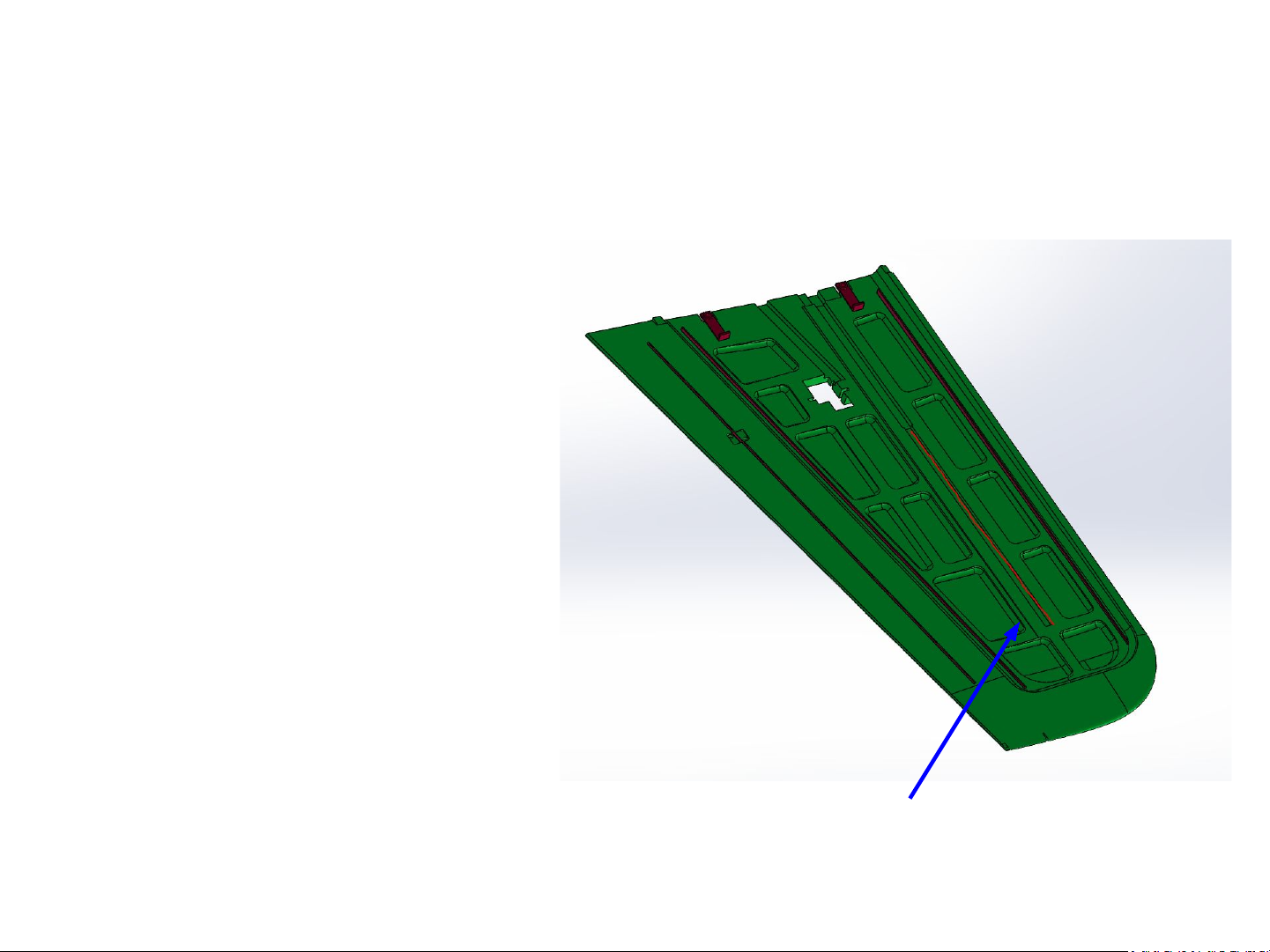
1. Glue components into wings
• Lay out the top halves of the
wings and glue in the spars
and wing anchors.
• Make sure the wing anchors
are in the correct position –
notice that one side is longer
than the other.
• Glue square hollow spar into
the channel marked with the
red line. Be sure to only glue
where the line is.
Glue along thin red line
7
Page 8
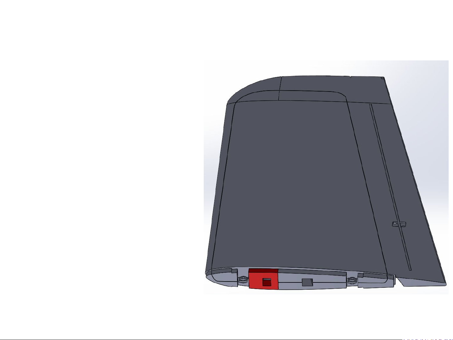
2. Glue wing halves together
• Carefully apply glue to all
mating surfaces, including
ribbon spars and square spar.
Do not get glue residue in
main spar channels
• Firmly press wing halves
together to ensure proper
adhesion.
• Glue on plastic wing caps.
(shown in red)
• Note: Servos can be installed
before, or after gluing wings.
8
Page 9
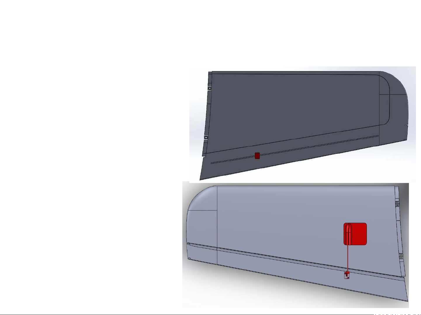
3. Install Servos & Control horns
• Servos can be installed
after wings are glued by
threading the servo
wire through the
channel in the wings.
Glue servos in place.
• Glue and screw control
horns in place and set
up linkages.
• Glue on covers over
servos.
9
Page 10
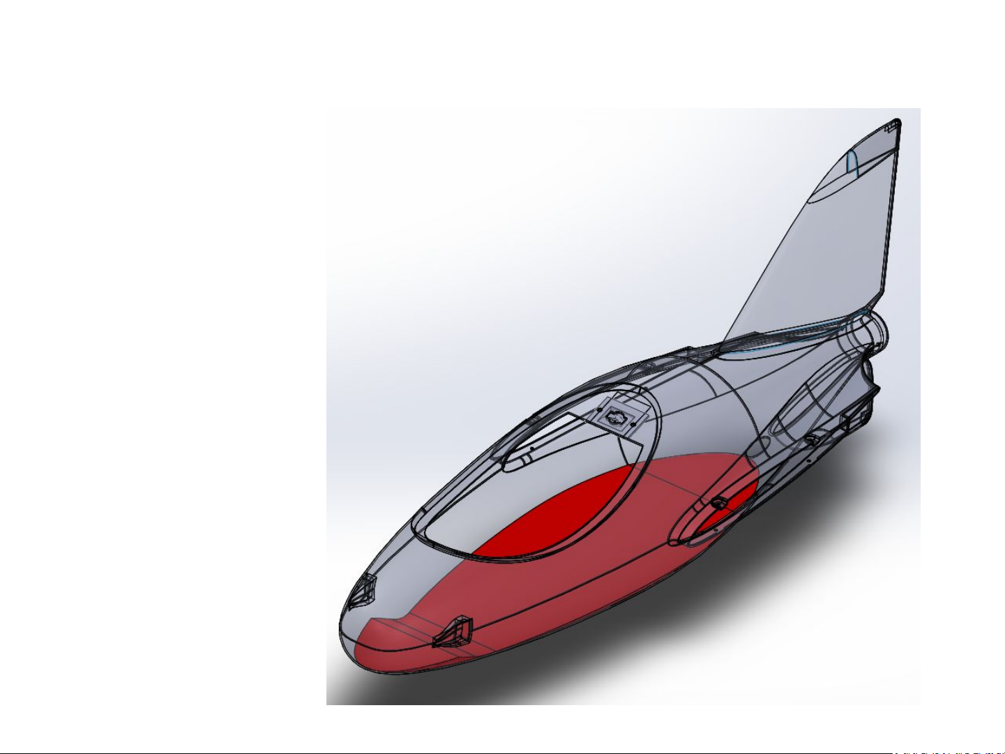
4. Glue foam into fuselage
• Glue wood tray to foam
core.
• Glue the foam core into
the fuselage.
10
Page 11
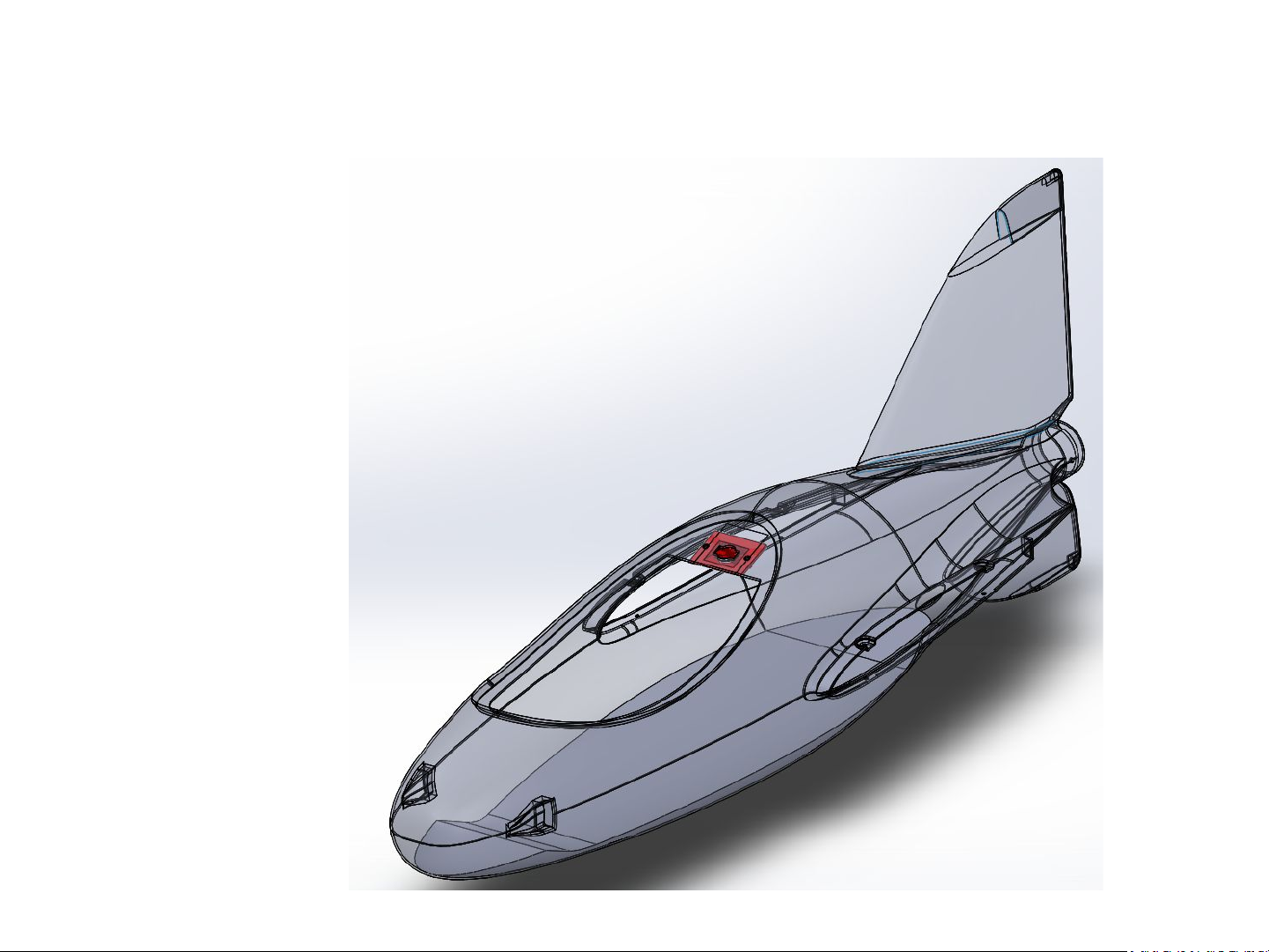
5. Install canopy latch receiver
• Screw the canopy latch
receiver plate into the
fuselage as shown.
11
Page 12
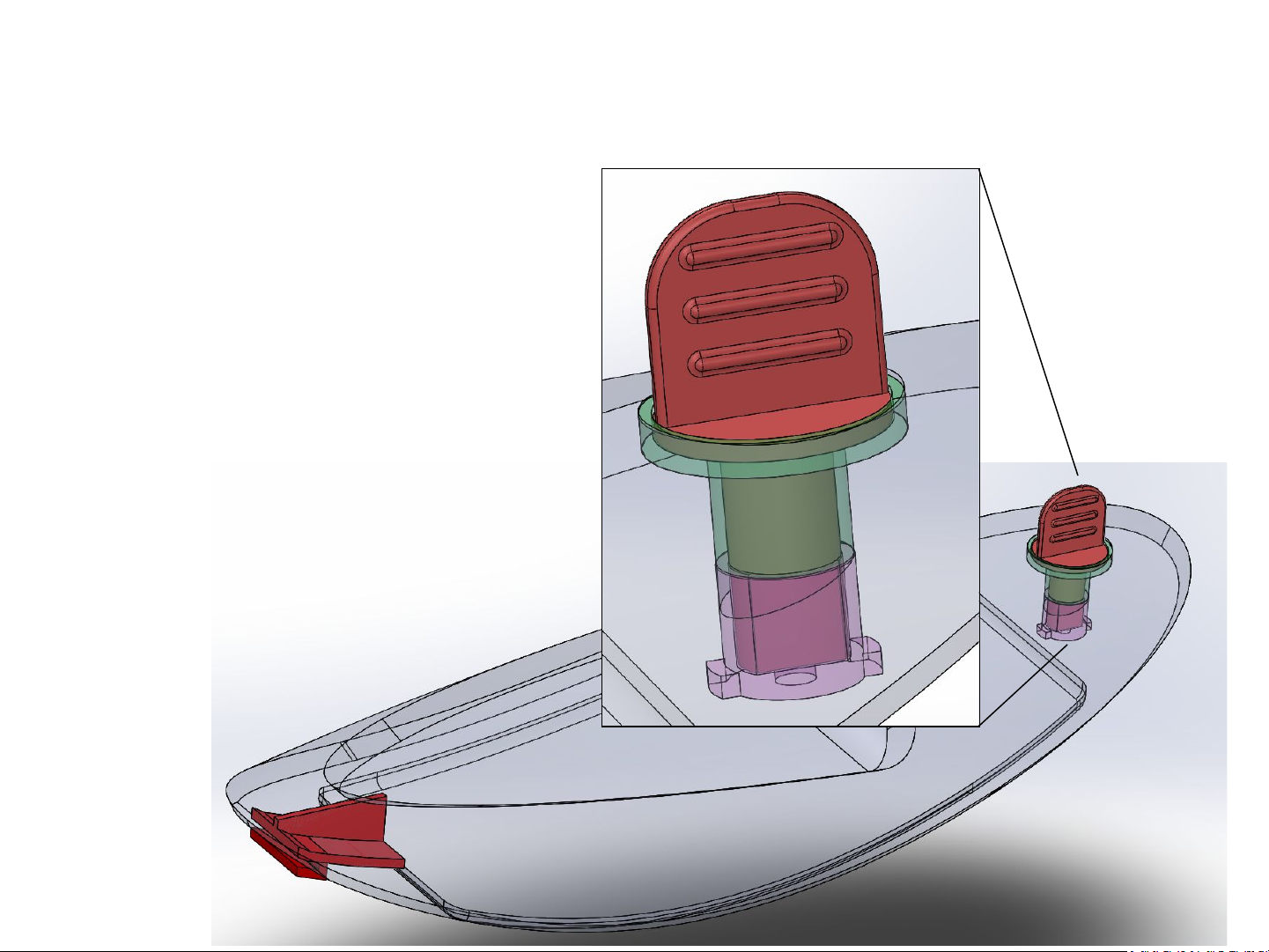
6. Assemble canopy
• Glue wood tray and
magnets into canopy.
• Glue in front latch.
• Assemble and glue
together rear latch
assembly. Ensure it can
still rotate!
12
Page 13
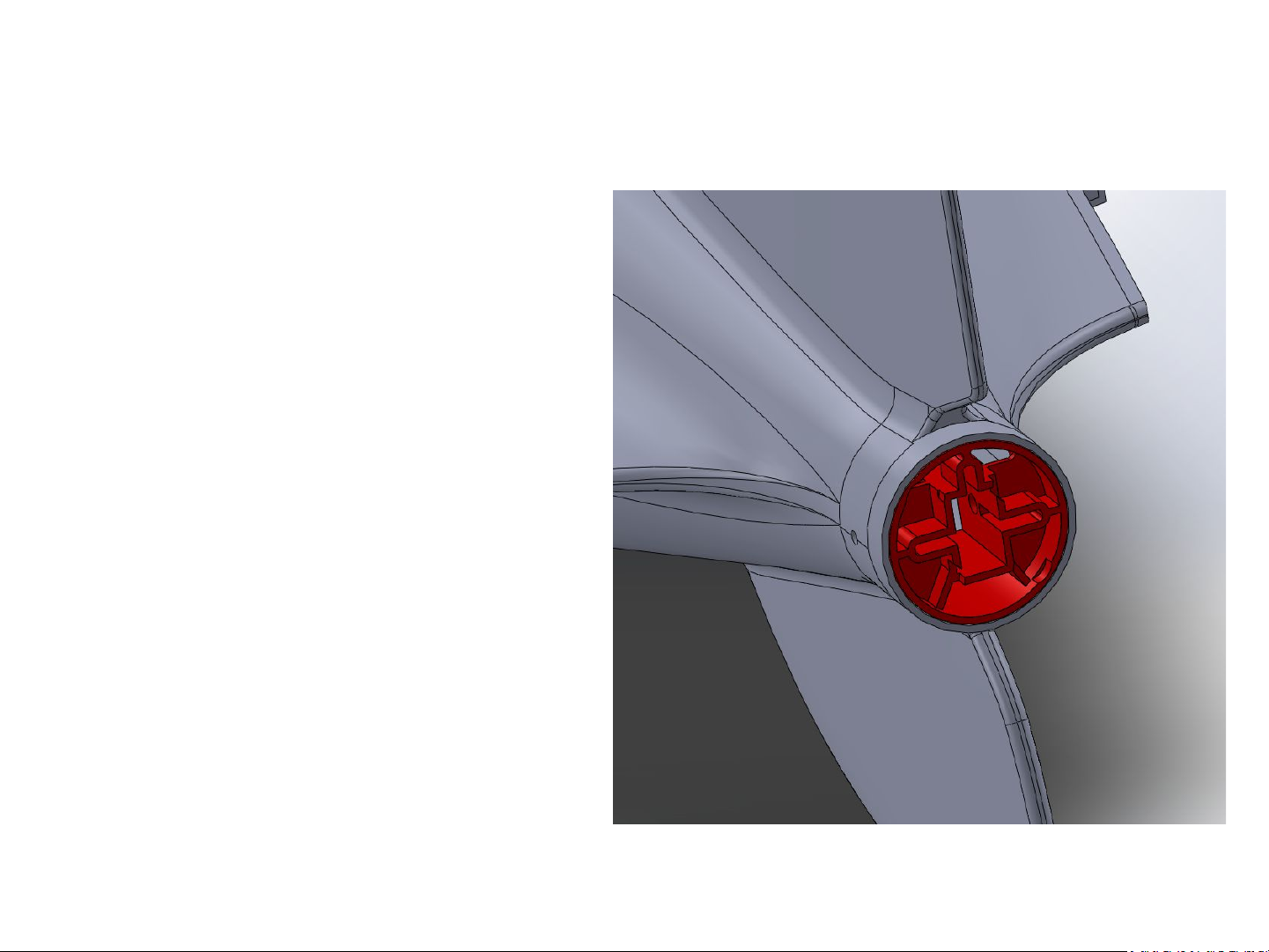
7. Install Motor Mount Receiver
• Install the motor mount
receiver into the opening
at the rear of the
fuselage.
• Ensure it is installed in the
proper orientation and
that the screws on the
side line up with the holes
in the fuselage – see
picture.
• If desired, it can be glued
in for additional support.
13
Page 14
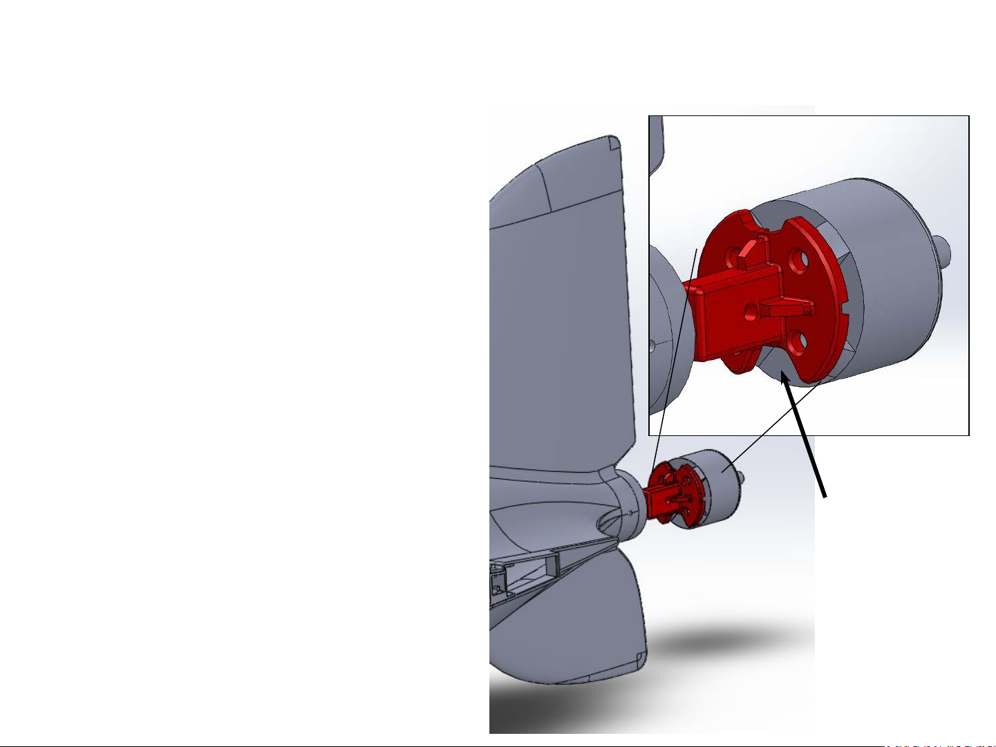
7. Install Motor
• Bolt motor to motor mount.
Check orientation of mount in
picture. Ensure bolts do not go
too far into the motor and
touch the windings.
• Carefully push the motor wires
through the bottom of the
motor mount receiver while
inserting the motor mount.
• Once fully inserted, secure the
motor mount and receiver
with bolts.
Motor wires
14
Page 15

8. Attach ESC
• Install ESC inside the
fuselage.
• Connect wires to motor
and test motor.
direction with servo
tester. (not included)
• Ensure power
connector can be easily
accessed through the
hatch.
15
Page 16
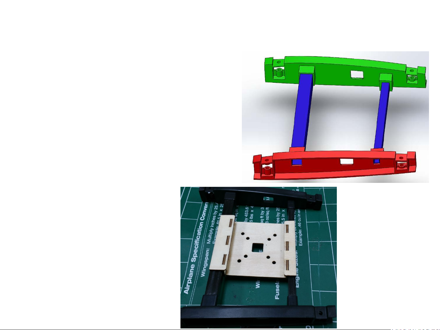
9. Assemble Wing Carriage
• Assemble plastic pieces
with carbon spars as
shown.
• Glue all parts together.
• Optionally install and
glue wood shelf as
shown.
16
Page 17

PNP Assembly Instructions
17
Page 18
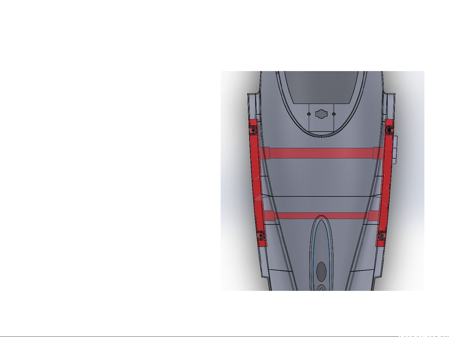
1. Insert Wing Carriage into Fuselage
• Insert the wing carriage
into the fuselage as
shown.
18
Page 19
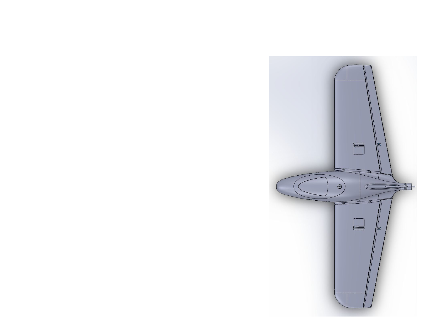
2. Install wings
• Install the main spar
into one of the wings,
and slide the wing onto
the fuselage. Push the
servo wire through the
provided hole in the
plastic side of the wing
carriage.
• Slide the other wing on.
• Secure wings with
provided M3 bolts.
19
Page 20
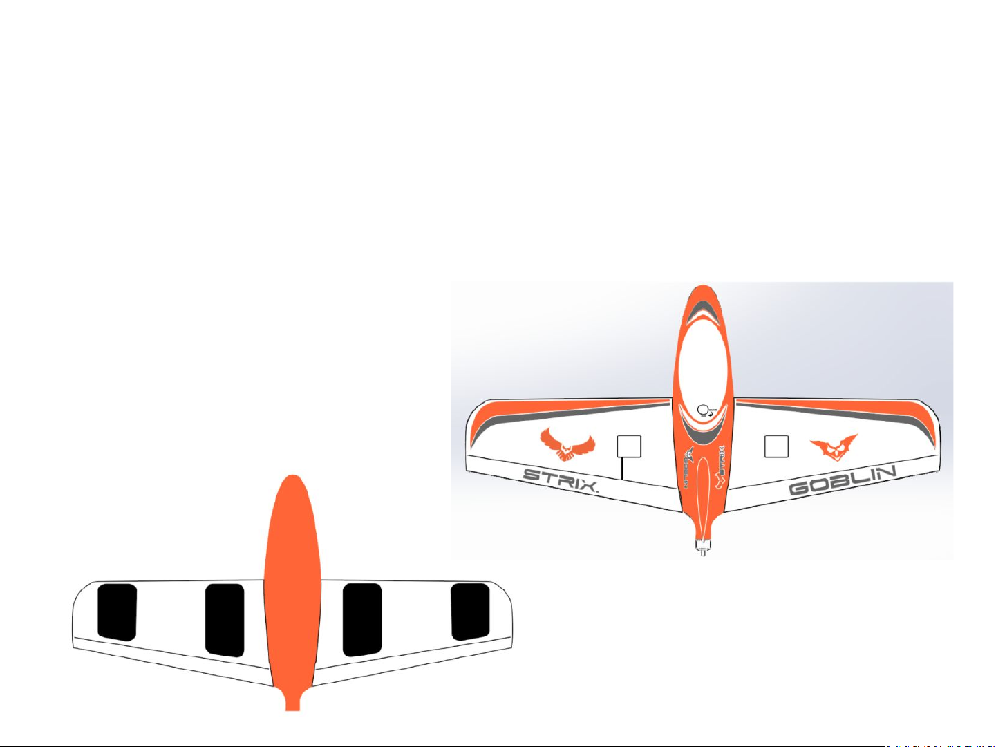
3. Apply Decals
• This is the intended decal layout, but of course you can decide that. Two clear
strips of decal have been included to apply to the bottom side of the wing on the
hinge line as reinforcement - this is optional, but recommended.
20
Page 21

4. Install and connect RC Receiver
• Connect your RC
receiver as necessary.
• Install battery.
• Check control surface.
movement as per the
beginning of this
document.
• Check CG. (31mm from
leading edge)
• GO FLY!
21
 Loading...