

LAZERTM LITE
Owner’s Manual
STOP
Solo® Germany The registered Solo® trademark is licensed for use in the U.S. to the German company Solo Kleinmotoren Gmbh by the U.S. aliate, Solo incorporated.
ATTENTION: PRIOR TO FIRST USE
Avoid damage...
Read this manual
thoroughly before
using the auger.
To operate your engine you will need to use a
clean, high-quality, 2-cycle oil. We recommend
StrikeMaster 2-cycle Low Smoke Engine Oil
mixed with fuel at a ratio of 40:1 (3.2 fl. oz. to 1
gallon of gasoline).
!!
For best performance idle
engine for 1-2 minutes
before you start drilling.
®
STRIKEMASTER
Ice Augers
Ice Fishing has become one of the fastest growing and most popular winter sports, allowing the ardent
angler the opportunity to enjoy his or her favorite outdoor activity.
®
When you purchased a StrikeMaster
reputation as the quality leader since 1946. There is no doubt that this year’s model is the finest ever
produced by StrikeMaster Corporation.
Your new StrikeMaster ice auger has all of the most wanted features in a power ice auger, to assure many
years of enjoyable ice fishing. Some of these features such as workmanship, engineering excellence, and
dependability have long been standards at StrikeMaster. Your new power ice auger boasts many new
features while retaining the best features developed in previous years to enhance your ice fishing
experience and add to your satisfaction in selecting StrikeMaster.
We know that you are anxious to go fishing and use your new power ice auger, but before you go fishing,
it is important and to your advantage to spend a few minutes getting acquainted with your new
StrikeMaster power ice auger. There is no better way to acquaint yourself with the product than to read
the Owners Manual and operating instructions. A few minutes spent studying this manual before your
first ice fishing outing will be time well spent.
power ice auger, you selected a product that has gained a
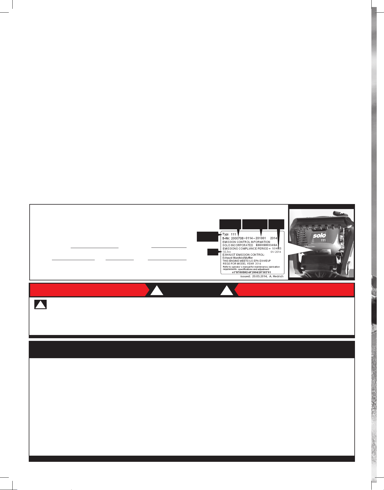
Record the engine serial number, engine type and date purchased in the space below.
Also, please return the enclosed WARRANTY CARD or submit your information at
www.strikemaster.com to validate your limited warranty.
Model: Chipper Lite
Serial Number Engine Type
Spec # CC DOM
Date Purchased ______ / ______ / ______
ENGINE
TYPE
ATTENTION
!
THIS SYMBOL POINTS OUT IMPORTANT SAFETY INSTRUCTIONS WHICH IF NOT FOLLOWED COULD ENDANGER
THE PERSONAL SAFETY AND/OR PROPERTY OF YOURSELF AND OTHERS. READ AND FOLLOW ALL INSTRUCTIONS
IN THIS MANUAL AND ANY PROVIDED WITH OR ON THE EQUIPMENT ON WHICH THIS ENGINE IS USED BEFORE
ATTEMPTING TO OPERATE YOUR STRIKEMASTER® POWER ICE AUGER.
SPEC #
CC
!!
SERIAL
NUMBER
DOM
TABLE OF CONTENTS
Important Safeguards/Component & Control Locations 3
Assembly Instructions 4
Simple Start-Up Steps 4
Fueling: Oil/Fuel Instructions 5
Engine Start Preparations 6
Engine Start Instructions 6
Stop Engine 6
Maintenance 7
Storage 7
.................................................................................................................................................................
................................................................................................................................................................
...........................................................................................................................................................................
SOLO® Engines Limited Warranty 9-10
STRIKEMASTER Limited Warranty (back cover)
..............................................................................................................................................
..............................................................................................................................................
.................................................................................................................................
.......................................................................................................................................
........................................................................................................................................
..................................................................................................................
................................................................................................
............................................................................

IMPORTANT SAFEGUARDS
!!
STOP STOP
Avoid damage...Read this manual thoroughly before using the auger.
1. DO NOT use this product for any purpose other than cutting ice fishing holes. Ice augers are precision cutting
tools built for the ice fisherman, and must be properly maintained and handled with caution during both cutting
and transporting. When not in use, always store with blade guard attached.
2. DO NOT use attachments other than those available from the manufacturer.
3. DO NOT alter this product in any manner; doing so is dangerous and voids all warranties.
4. DO NOT allow children or adults weighing under 100 lbs. to operate this equipment.
5. DO NOT operate under the influence of drugs or alcohol.
6. DO NOT allow your body, loose clothing, drawstrings, scarves, hats or other materials to come in contact with
the Powerhead, Starter Assembly or Auger (Drill) unit at any time.
7. DO NOT operate if, upon pulling the starter rope or after drilling holes, the auger (drill) rotates or if the rope
pulls hard. Have the unit checked by a qualified mechanic.
8. DO NOT allow the engine to run or operate while moving or transporting to another location.
9. DO NOT continue to use this product in the event of mechanical or electrical failure.
10. This product produces considerable cutting force that is felt by the operator. Make sure your feet are firmly
planted and that the handles are held firmly while operating this product.
11. Always check the operation of the throttle system to ensure the carburetor control is completely returning to
the idle position when the throttle lever is released.
12. Check cutting blades and auger shaft screws before and after each use to make sure they are tight.
13. During operation, the auger unit could possibly stop. Be prepared at all times to release the throttle lever.
14. The cutting blades on the ice auger are razor sharp. Use extreme care when handling.
PACKAGING & DISPOSAL
! !
Please keep the original packaging in order to protect the equipment against damage in case you ever need to ship or
transport the auger. If the packaging materials are no longer required then they must be disposed of properly in accordance
with applicable local regulations. Cardboard packaging materials are raw materials which can be recycled or reused. At the end
of the equipments service life, please make sure that you dispose of it properly, in accordance with the ocial directives and
regulations that apply in your area.
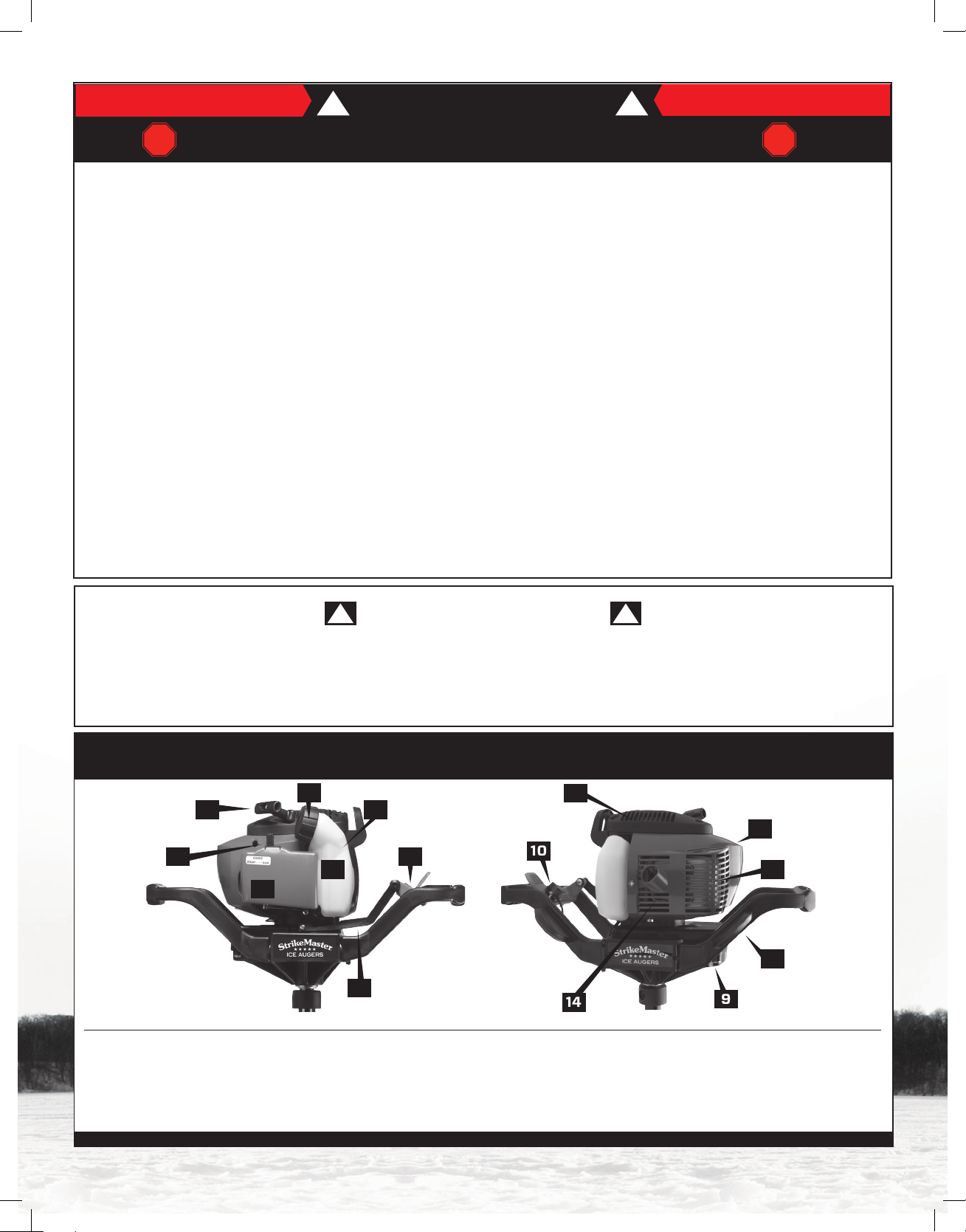
COMPONENT & CONTROL LOCATIONS
2
1
8
6
4
5
3
7
10
12
14
11
13
15
9
1. Recoil (starter) Handle
2. Fuel Cap
3. Fuel Tank
4. Fuel (FULL) Level
5. Throttle Lever
6. Air Filter Cover
7. Throttle Arm
8. Choke Lever
9. Transmission
10. Start/Stop Switch
11. Spark Plug Cover
12. Recoil Starter
3
13. Muer/Cylinder Guard
14. Muer
15. Handle Assembly

!
Carefully remove blade
1
guard and make sure
blade bolts are tight.
(Use 8mm closed end
wrench for Lazer blades)
Remove Metric Allen
2
wrench attached to the
neck of the auger and
unscrew the collar bolt
from auger.
The large and small
2a
holes from each
component must line
up before installing
the collar bolt.
Push down and twist
to line up holes.
1
2
Plastic
Collar
2a
Large
Holes
ASSEMBLY
! !
It is recommended to
3
grease inside metal collar and
Lazer
Blade
transmission output shaft on the
powerhead. Standard automotive
wheel bearing grease is suggested.
Insert drive shaft into auger and
install collar bolt.
Collar bolt inserts into the large
Metal Collar
Allen
Wrench
3a
hole, passing through the drive
shaft and threads into small hole
of metal collar. Tighten bolt. Some
Collar Bolt
wiggle is normal between the power
head and auger. Tighten often.
After assembly is complete, you
4
can conveniently store your allen
wrench on the underside of the
throttle pedal.
It is recommended that the blade
and collar bolts be checked and
torqued firmly before and after
every use.
SIMPLE START-UP STEPS
! !
3
Output Shaft
3a
4
Allen Wrench
Storage
1. Turn kill switch to the “ON” position.
2. Pump the primer bulb until it is full of fuel.
3. Move the choke lever to the “START” position.
4. SLOWLY pull recoil handle out until the flywheel engages.
5. Pull the recoil with an assertive, short pull.
6. Pull the recoil until the first audible “fire” of the engine is heard (Should be 2-4 pulls).
7. Quickly move the choke lever to the “RUN” position.
8. If the engine dies, pull over 1-2 more times.
Light pressure on the throttle lever after startup may be needed in extremely cold conditions raising the engine’s
RPMs to warm up the motor.
After using this machine, STOP the engine by allowing the engine to
return to idle and moving the switch to the OFF position. If engine fails
to stop, move choke lever to start position. DO NOT OPERATE until this
issue has been repaired by a qualified mechanic. Always check to make
sure the throttle system is moving freely and returning to idle. Turn o
this machine when traveling from fishing site to fishing site. Always
store auger with blade guard attached.
4

FUELING: OIL/FUEL INSTRUCTIONS
! !
Your new 2-stroke Solo auger engine does not come filled with a
fuel/oil mix. You will need to add a fuel/oil mix prior to your first use.
(See below) Fuel is highly flammable. Keep away from open flames
and never spill fuel. Do not smoke at the operating site or near the
refueling site.
• Stop the engine prior to refueling.
• Let the engine cool down before refueling.
• Open fuel cap slowly to allow any excess pressure in the tank to be
reduced without the risk of fuel spraying out.
• Fuel may contain substances similar to solvents. Wear protective
gloves during filling.
• Avoid breathing in fuel vapor.
• Immediately clean any spilled fuel on the machine.
• Firmly tighten fuel cap.
• Check for fuel leaks. Do not start the machine or work with the
machine if there is a fuel leak.
• Store fuel and oil in an approved and correctly labeled container.
1. The Solo engine has a non-vented gas cap which is not visible.
Air is supplied to the tank using an external venting system. (Fig 1)
2. You will notice the air line located under the fuel cap. The airline
needs to maintain this position in order to allow air to the tank. (Fig 2)
3. To prevent excessive fuel from collecting in the air line we have
the following suggestions. DO NOT OVER FILL THE GAS TANK.
4. When the auger is not in use, lay it down as shown. Position #1 (Fig 3)
is the best option followed by position #2. (Fig 4)
This will keep the air line out of the fuel.
Fig 1
AIR VENT PART #2700430
Fig 2
AIR LINE PART #64474
Fig 3
FUEL INFORMATION
• Use unleaded regular, unleaded premium or non-oxygenated
fuel. Do not use fuel with less than an octane rating of 87. For peak
performance use a 90-93 octane rated unleaded premium fuel.
• Do not use leaded fuel or E85.
• FUEL MUST BE FRESH AND CLEAN. NEVER use fuel left over
from last season or fuel that has been stored more than 30 days.
Do not use summer blend fuel; only use winter blend fuel which is
available after November 1st.
• Unsuitable fuel or deviations in mixing ratio may lead to serious
engine damage which is not covered under warranty.
2-CYCLE OIL/FUEL MIX
To operate your engine you will need to use a clean, high-quality,
2-cycle oil. We recommend StrikeMaster 2-cycle Low Smoke Engine
Oil mixed with fuel at a ratio of 40:1 (3.2 fl. oz. to 1 gallon of gasoline).
DO NOT use a fuel/oil mixture leaner than 50:1 (2.6 fl. oz. to 1 gallon
of gasoline).
• All 2-stroke engines will have some oil residue that slowly comes
from the muer area; this is normal.
• Full Synthetic 2-stroke oil may be used as long as fuel/oil mixture
ratio does not exceed 50:1 (2.6 fluid oz. oil to 1 gal. gas).
POSITION #1
When not in use
Fig 4
POSITION #2
When not in use
5

ENGINE START PREPARATIONS
!
!
• Check the complete machine for operational safety.
• The stop switch should function properly.
• The throttle must have freedom of movement and return to the idle
position on its own accord.
• The auger blades and collar bolt must be tightly secured and in
excellent working order.
• Ensure the spark plug cap and ignition cable are connected firmly.
• Remove fuel cap to ensure that the vent tube is up in the filler
tank neck and not pushed down or submersed in fuel.
ENGINE START INSTRUCTIONS
!
1. Turn the ON/OFF switch to ON. Make sure to read the
switch correctly. As shown above. (Fig 1)
2. Press the primer bulb (Fig 2) 5 to 8 times.
3. Slide the choke lever to START position. (Fig 3)
4. Pull the recoil slowly until engagement to flywheel is felt, then
continue pull with a slightly quicker motion until engine fires.
(Audible sound)
Once the motor has fired, slide the choke lever to RUN (Fig 4)
(no choke), and continue. Repeat step 4 until engine starts.
If engine fails to start, repeat steps 1-4.
Fig 1
Fig 2
Fig 3
!
Primer
Bulb
Choke Lever
(Start Position)
STARTING TIPS: As you know, very cold temperatures make all engines
a little harder to start. Whenever possible, keeping your machine in a
warm environment will ALWAYS make it easier to start.
Fig 4
If the engine fails to start after several attempts, check that all
adjustments described above have been done correctly.
Be sure the on/o switch is NOT in the o position and start once
again. If the engine still fails to start, contact your local Solo
authorized repair center located on our website.
Choke Lever
www.strikemaster.com
STOP ENGINE
! !
(Run Position)
After completing the cutting of an ice fishing hole, STOP the engine by allowing the engine to return to idle and
moving the ON/OFF switch to the OFF position. If engine fails to stop, slide choke lever to start (full choke). Do not
operate until this issue has been repaired by a qualified mechanic.
6

MAINTENANCE
! !
AIR FILTER
Contaminated air filters cause a reduction in engine
performance and increase fuel consumption with more
pollutants in the exhaust gas. Engines are less likely to
start readily with a contaminated air filter.
As a basic principle therefore, the air filter should be
cleaned as follows before starting work, and
intermittently in very dusty conditions:
Use spark plugs with the following description:
BOSCH: Super R10 USR4AC (Original plug included,
gap .020 inch)
NGK: CMR6H or comparable (Replacement/
Service plug .025 inch.)
Only use spark plugs where the contact nut has been
firmly fitted. Loose connections may produce sparks,
which can cause fire. Before restarting the engine,
check the high-tension ignition cable for any damage to
it’s insulation and ensure the cable is connected
securely to the spark plug cap.
• Insert the spark plug into the cylinder head and
tighten it.
• Push the spark plug cap firmly over the spark plug.
• Position the spark plug cover onto the housing by
aligning it with the guiding pins, push down and click
into place.
Before opening the air filter, close the choke to prevent
dirt entering the carburetor.
• Push tab (a) in, only slightly open air filter lid (11) and
remove by rotating gently back and forth.
• Remove foam filter (c) from the lid and clean the area
around the filter.
• Thoroughly clean air filter casing (d) and air filter
cover (11) on the inside, using a paintbrush or by
carefully blowing on them.
• Clean filter insert (c) by shaking it out or carefully
blowing on it.
If the filter insert is damaged or so contaminated that it
is impossible to clean, replace it with the original spare
part (part no. 20 48 406).
• Insert the new or cleaned foam filter into the
air filter lid.
• Position the air filter cover with both tabs (b) [inside,
opposite tab (a)] in the corresponding two pockets
(b’) of the filter casing.
• Press air filter cover against the filter casing until tab
(a) clicks audibly into place.
SPARK PLUG
Check the spark plug annually.
• Engine must be cool.
• Press the top tab of the spark
plug cover (16) down (a),
push back (b) and remove.
• Disconnect the
spark plug cap.
• Unscrew the spark plug
and dry electrodes.
The spark plug should be replaced after 50 hours of
operation or if the electrodes are badly worn.
Do not turn the engine over while the spark plug has
been removed or the spark plug cap has been
disconnected from the ignition cable.
.025 inch
TRANSMISSION
Transmissions are maintenance free, they require no
adding of grease or checking.
SECURING YOUR AUGER DURING TRANSPORT
With your purchase of a StrikeMaster power auger, you
have acquired one of the world’s best precision cutting
machines. A little prevention goes a long way. Whether
you transport this machine in a truck, snowmobile, ATV
or sled be sure to secure it down to prevent damage.
STORAGE
! !
Because of today’s fuels STRIKEMASTER cannot
guarantee results. For summer storage or any period of
time exceeding four weeks, the following steps should
be carried out:
WET/NORMAL STORAGE : (recommended)
• Empty fuel tank contents and dispose of properly
• Fill fuel tank to 1/4 capacity with fresh fuel,
oil and stabilizer
• Start and run engine for 2-3 minutes, varying throttle
input, then turn switch to the OFF positron
• If possible, run engine every 30 days for 2-3 minutes.
DRY STORAGE:
• Empty fuel tank contents and dispose of properly
• Fill fuel tank to 1/4 capacity with fresh fuel,
oil and stabilizer
• Start and run engine for 2-3 minutes, varying throttle
input, then turn switch to the OFF position
• Empty fuel tank contents
• Restart engine and allow engine to idle until engine
stalls (due to lack of fuel)
Suggested steps for general cleaning and storage:
• Spray WD-40 or apply oil onto the blades and blade
screws to reduce rust and corrosion
• Clean the engine thoroughly with a clean cloth
• Place a cover over engine assembly
• Store indoors in a well-ventilated low humidity area
• Store auger with blade guard attached
7

Tony Roach
Ice Force Pro Angler

®
Solo® Germany-The registered Solo® trademark is licensed for use in the U. S from the
German company Solo Kleinmotoren Gmbh by the U.S. aliate, Solo incorporated.
Transmission: Transmissions are maintenance free, they require no adding of grease or checking.
LIMITED WARRANTY
The manufacturer warranties trouble-free quality and will cover the cost of replacing parts which are found to be
faulty in material or workmanship within the prescribed warranty period after the date of purchase. Please note
that specific warranty conditions may vary from country to country. If in doubt, ask your equipment vendor. They are
responsible for warranty matters. Solo Inc. provides the initial purchaser with a 2 year engine warranty.
We hope you will understand that we cannot be liable for damage resulting from the following causes:
• Non-compliance with the operating instructions.
• Neglecting essential maintenance and repair work.
• Damage caused by incorrect carburetor adjustment.
• Wear and tear from normal use.
• Obvious overload by continuously exceeding the maximum performance limit of the product.
• Using non-authorized tools.
• Use of force, incorrect treatment, misuse and accidents.
• Damage from excessive heat due to dirt buildup around the cooling fan housing.
• Attempted adjustments and repairs by unqualified persons.
• Use of unsuitable spare parts or third party parts, if these are the cause of the defect.
• Use of unsuitable or stale fuel.
• Damage caused by using the product in the hire or rental industry.
Normal cleaning, adjustments or maintenance work fall outside the warranty provisions. A service center authorized
by the manufacturer must carry out all warranty work.
!!
9

EC DECLARATION OF CONFORMITY
In accordance with EG Directives 98/37/EC,
2000/14/EC and 89/336/EEC (amended by
92/31/EEC), SOLO Kleinmotoren GmbH,
Stuttgarter Strasse 41, D-71069 Sindelfingen,
being solely responsible, states that the product
referred to in this declaration complies with the
requirements of the Machinery Directive.
Description of product: Ice Auger
Model/Type description 111 142 154
Sound power level
Guaranteed sound
Actual sound 94 111 111 dB(A)
105 112 112 dB(A)
PARTS SUBJECT TO WEAR AND TEAR
Various parts are subject to application-specific or
normal wear and must be replaced when required.
The following parts are subject to normal wear and
are not covered by the manufacturer’s warranty:
• Air filter
• Fuel filter
• All rubber parts which come into contact with fuel
• Clutch
• Spark plug
• Starter (Recoil)
• Blades
(EN ISO 3744, EN ISO 22868)
Applied standards: EN ISO 12100, EN 11806,
ISO 14865, EN ISO 14982
Conformity assessment procedures
(98/37/EG) - Appendix V
(2000/14/EG) - Appendix V
Serial number, Build year - Type plate
This declaration of conformity loses its validity, if the
equipment is converted or modified without the
manufacturer’s consent.
Sindelfingen, 1st January 2006
SOLO Kleinmotoren GmbH Wolfgang Emmerich
Executive Director
FOR USA ONLY
Emissions Control Warranty Statement
The Environmental Protection Agency and Solo are
pleased to explain the emission control system on your
small non-road power equipment engine. In the US new
small non-road engines must be designed, built, and
equipped to meet the Environmental Protection
Agency’s standards. Solo must warrant the emission
control system on your small non- road engine for the
period of time listed below provided there has been no
abuse, neglect, or improper maintenance of your small
non-road engine.
Your emission control system includes parts such as the
carburetor, the ignition system and the exhaust system.
Where a warrantable condition exists Solo will repair
your small non-road power equipment engine at no cost
to you including diagnosis, parts, and labor.
10

LIMITED WARRANTY
The warrantor’s obligation shall be limited to repairing or replacing any part, which upon examination by StrikeMaster, is determined to be defective. This obligation
begins on the date of purchase (as evidenced by a product receipt) and continues for a period of ONE YEAR after purchase (“warranty period”), with the exception of
engines and parts subject to wear and tear. This warranty is non-transferrable; warranty registration must be completed online or via USPS within 30 days of purchase
to validate warranty. The warranty does not apply if product has been negligently used, misused, altered, damaged in an accident or if periodic maintenance has not
Company warrants that Product, other than engines and parts subject to wear and tear, will perform substantially in accordance with the accompanying written
materials [owner’s manual] for a period of ONE YEAR. In the case of engines and parts subject to wear and tear, please refer to the chart below. Parts subject to
normal wear and tear are not covered by warranty including: air filter, fuel filter, any rubber part that comes in contact with fuel, clutch, spark plug, starter (recoil), 12
volt batteries and blades. In the event applicable law imposes any implied warranties, the implied warranty period is limited to ONE YEAR from the date reflected on the
product receipt. Some jurisdictions do not allow such limitations on the duration of an implied warranty, so the above limitation may not apply.
TO THE MAXIMUM EXTENT PERMITTED BY APPLICABLE LAW, THE COMPANY AND AUTHORIZED SERVICE CENTERS DISCLAIM ALL OTHER WARRANTIES, EITHER
EXPRESS OR IMPLIED, INCLUDING, BUT NOT LIMITED TO IMPLIED WARRANTIES OF MERCHANTABILITY AND FITNESS FOR A PARTICULAR PURPOSE WITH REGARD TO
THE PRODUCT AND WRITTEN MATERIALS [OWNER’S MANUAL]. THIS LIMITED WARRANTY GIVES CUSTOMER SPECIFIC LEGAL RIGHTS. CUSTOMER MAY HAVE OTHER
TO THE MAXIMUM EXTENT PERMITTED BY APPLICABLE LAW, IN NO EVENT SHALL THE COMPANY OR AUTHORIZED SERVICE CENTER BE LIABLE FOR ANY DAMAGES
WHATSOEVER (INCLUDING WITHOUT LIMITATION, SPECIAL, INCIDENTAL, OR CONSEQUENTIAL OR INDIRECT DAMAGES FOR PERSONAL INJURY, LOSS OF BUSINESS
PROFITS, BUSINESS INTERRUPTION, LOSS OF BUSINESS INFORMATION OR ANY OTHER PECUNIARY LOSS) ARISING OUT OF THE USE OF OR INABILITY TO USE THIS
PRODUCT, EVEN IF THE COMPANY HAS BEEN ADVISED OF THE POSSIBILITY OF SUCH DAMAGES. IN ANY CASE, THE COMPANY’S AND AUTHORIZED REPAIR CENTER’S
ENTIRE LIABILITY UNDER ANY PROVISION OF THIS AGREEMENT SHALL BE LIMITED TO THE AMOUNT ACTUALLY PAID BY YOU FOR THE PRODUCT. BECAUSE SOME
JURISDICTIONS DO NOT ALLOW THE EXCLUSION OR LIMITATION OF LIABILITY FOR CONSEQUENTIAL OR INCIDENTAL DAMAGES, THE ABOVE LIMITATION MAY NOT
been performed. Customer is responsible for shipping and transportation charges to the nearest warranty repair center.
RIGHTS DEPENDING ON THE JURISDICTION.
APPLY TO YOU.
Continued satisfying performance from your StrikeMaster power ice auger may be assured by applying a minimum amount
of preventive maintenance.
Limited Warranty coverage
(with receipt/proof of registration)
Wear & tear parts X
12-Volt Battery X
StrikeMaster parts X
Solo engine X
Honda engine X
Lithium Lazer motor X
Lithium Lazer battery X
30-Day
Warranty
90-Day
Warranty
1-Year
Warranty
2-Year
Warranty
3-Year
Warranty
Visit our website for up to date warranty service centers.
www.strikemaster.com
 Loading...