

Striem
3100 Brinkerhoff
Kansas City, KS 66115
Tel: 913-222-1500
Fax: 913-291-0457
www.
striemco.com
Made in the U.S.A
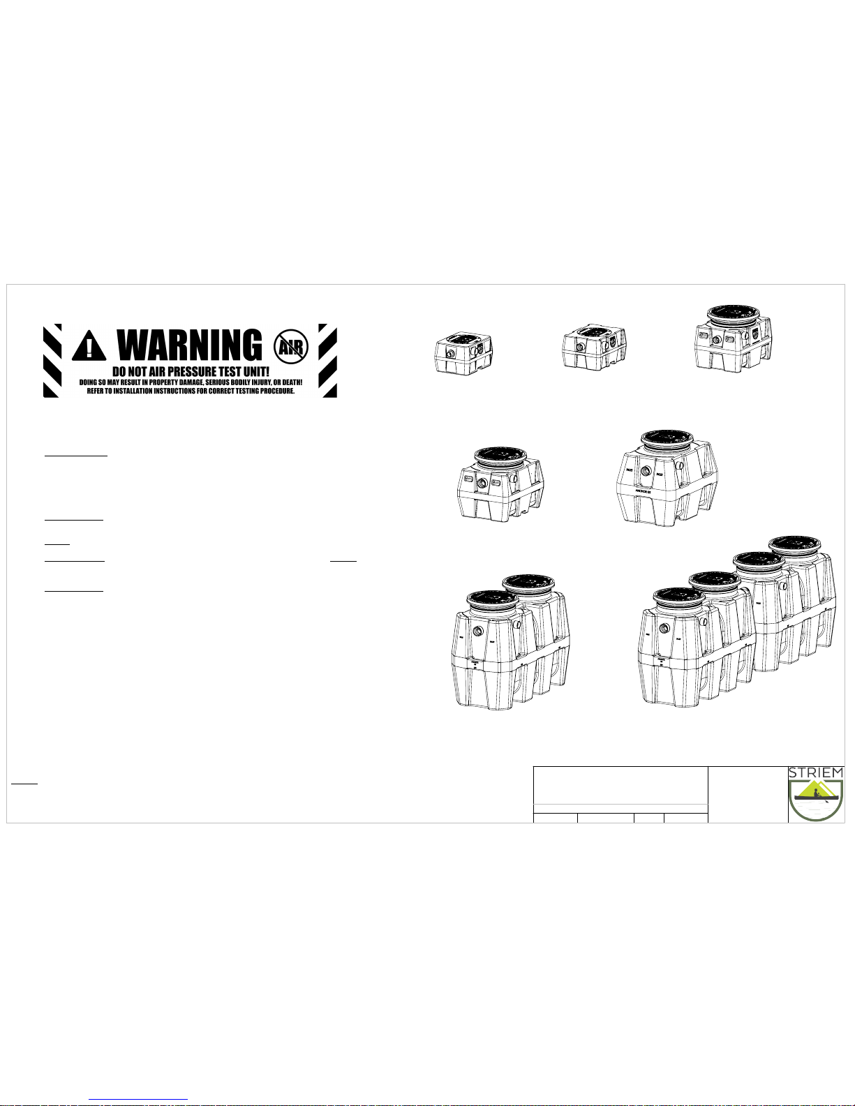
OS-15
15 gpm, 15 gallons
10 gallon oil capacity
1 gallon sand capacity
OS-25
25 gpm, 21 gallons
15 gallon oil capacity
6 gallon sand capacity
OS-35
35 gpm, 38 gallons
28 gallon oil capacity
6 gallon sand capacity
OS-50
50 gpm, 57 gallons
40 gallon oil capacity
7 gallon sand capacity
OS-75
75 gpm, 110 gallons
93 gallon oil capacity
11 gallon sand capacity
OS-100
100 gpm, 250 gallons
144 gallon oil capacity
95 gallon sand capacity
OS-500
100 gpm, 500 gallons
288 gallon oil capacity
95 gallon sand capacity
Sheet Descriptions
Sheet #1 - Series overview and Warranty information
Sheet #2 - OS General installation guidelines and Operation/Maintenance guidelines
Sheet #3 - Below Grade installation guidelines
Sheet #4 - Below and Above Grade installation guidelines
Sheet #5 - Multiple unit systems. Setting the oil draw off
Sheet #6 - OCT General installation guidelines and Operation/Maintenance guidelines
Sheet #7 - TeleGlide Riser installation guidelines (SR24, LR24)
Sheet #8 - TeleGlide Riser installation guidelines (SR16)
Leak/Seal Testing
DO NOT AIR TEST UNIT OR TELEGLIDE RISER SYSTEM! Doing so may result in property damage, personal injury or death.
Base Unit:
To perform a leak/seal test on the base unit, cap/plug all plumbing connections, remove the cover, and fill the unit with water just above the
highest connection. Inspect unit and connections for leaks. Check water level at specific time intervals per local code.
TeleGlide Riser System:
If required by local code, the riser system may be leak/seal tested similar to the base unit.
CAUTION:
the riser(s) must be supported
before filling with water to keep from tipping over. Once riser system is in place and properly supported, cap/plug all plumbing connections on the main unit,
remove the cover from the top of the riser assembly and fill the unit and riser system with water to finished grade level. Carefully, as the riser(s) will be very
heavy from the weight of the water, inspect all gasket(s) and clamps (if applicable) for any leaks. Check water level at specific time intervals per local code.
Lifetime Warranty
Effective March 2, 2015 Striem represents and warrants that HDPE and PP products will be free from any
and all defects in material and workmanship, including corrosion, during the lifetime of the plumbing system in which the Products were originally
installed and will, at its option, agree to repair, replace, or supply credit to the original purchaser.
This warranty does not cover damage caused by the Products’ normal usage, or wear and tear, nor does it cover damage from naturally occurring
phenomenon, including, but not limited to UV, freeze-related damage, or natural disasters. This warranty does not cover the purchaser’s cost of routine
maintenance including replacement of parts required in routine maintenance.
This warranty does not cover fabricated steel products, or any monitoring equipment. This warranty shall be effective if, and only if, the Products:
* Were installed in accordance with Striem’s notes, specifications and instructions, for installation, operation, and maintenance;
* Were installed in conformance with all applicable building and plumbing codes, and passed all applicable testing methods immediately following installation;
* Have not been subjected to misuse or abuse, whether negligent or intentional;
* Were never modified, repaired, or altered by any individual(s) not authorized by Striem.
This warranty is the purchaser’s sole and exclusive remedy, and acceptance of this exclusive remedy is a condition of the contract for thepurchase of these
Products. In no event shall Striem be liable for any incidental, special, consequential or punitive damages, or for any costs, attorney fees, expenses, losses or
delays claimed to be as a consequence of any damage to, failure of, or defect in any products including, but not limited to, any claims for loss of profi ts,
transportation, removal and installation charges. This warranty is exclusive and in lieu of all other warranties or conditions, written or oral, expressed or implied.
OIL RESERVE OIL SEPARATORS
(Models OS-15, OS-25, OS-35, OS-50, OS-75, OS-100, and OS-500)
OS & OCT SERIES INSTALLATION,
OPERATION AND MAINTENANCE GUIDE
ECO:
8/15/18MJREV:
DATE:
DWG BY:
DESCRIPTION:
PROPRIETARY AND CONFIDENTIAL
THE INFORMATION CONTAINED IN THIS DRAWING IS THE SOLE PROPERTY OF
STRIEM, LLC.
ANY REPRODUCTION IN PART OR AS A WHOLE WITHOUT THE WRITTEN PERMISSION OF
STRIEM, LLC.
IS
PROHIBITED.
NOTES:
Striem oil separators are rated and manufactured with an internal flow control system already in
place. They do not require an external flow control system or air intake vent.
Striem oil separators are not to be installed in any other manner except as shown. Consult local
codes for separate trapping requirements, cleanout locations and additional installation instructions.
SHEET NUMBER:
1 of 7
Striem
3100 Brinkerhoff
Kansas City, KS 66115
Tel: 913-222-1500
Fax: 913-291-0457
www.
striemco.com
Made in the U.S.A
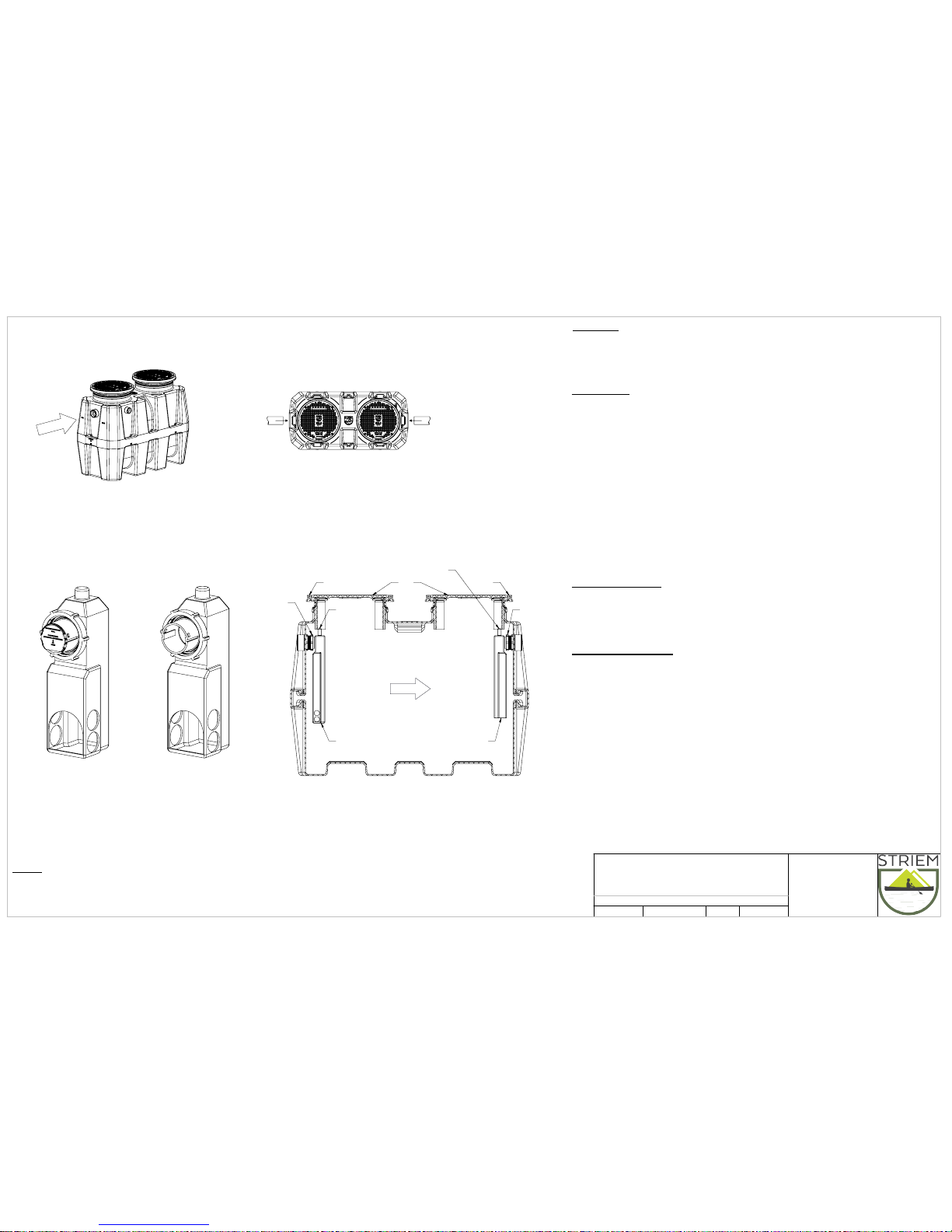
Connect inlet and outlet drainage lines to
unit. Mechanically couple pipes to
unit.
Do not solvent weld
. If connecting
multiple units for an engineered oil
separator system refer to multiple unit
installation sheet. (sheet #5)
Top View
FLOW
Isometric View
Set unit on level solid surface as close as
possible to fixtures being served. If unit is
to be installed below grade refer to below
grade installation instructions. (sheet #3)
FLOW
OS-100 SHOWN
Locking Collar
Cover
Adapter
Locking Collar
Inlet Disffuser
Outlet Diffuser
Open Top
Closed top outlet diffuser
to provide sewer gas trap
Adapter
MAINTENANCE
For most thorough cleaning contact a professional pumper contractor.
1.
Wear appropriate safety equipment when cleaning. Do not smoke near separator or clean near open
2.
flame or sparks.
Remove cover(s).
3.
Remove coalescing media (if applicable) and thoroughly wash down into appropriate container.
4.
Remove all contents of the separator including oil, sediment
5.
and wastewater.
To access the inlet and outlet lines for cleaning as needed:
6.
a.) 4" connections: Remove the inlet and outlet diffusers
(inside unit(s)) by hand loosening
green locking collars.
b.) 6" connections: Remove threaded clean-out plug from the back
of the inlet and outlet diffusers.
Clean the drain lines, diffusers and air relief thoroughly of all
7.
debris before replacing diffusers to original positions or reinstalling
threaded clean-out plug.
Fill unit(s) with water.
8.
Inspect gasket for wear and tear. Replace cover(s).
9.
Dispose of oil per local code.
10.
PUMPING FREQUENCY:
Frequency depends on the capacity of the separator and the amount of oil and sediment in the wastewater.
After initial installation, it is recommended that the unit is fully pumped every 3 to 4 weeks. Monitor each pumping
to establish an adequate maintenance schedule Striem Products recommends pumping frequency to exceed no
more than 6 months.
TROUBLESHOOTING TIPS:
In the case of a clog, inlet and outlet diffusers may be removed for line cleaning. Slower than usual drainage may
indicate the need to pump/clean oil separator. Units with 6" connections have a removable plug on the back of the
diffuser as the diffuser itself is not removable.
Always take proper care to ensure a safe and healthy environment while cleaning separator. For best cleaning and
maintenance service, call your local sewer and drain contractor.
GENERAL SEPARATOR INSTALLATION INSTRUCTIONS
(OS-100 SHOWN)
OPERATION
Striem Oil Separators are engineered to separate oil and other lighter-than-water contaminants from
wastewater to keep them from entering the sewage system. This is accomplished using Striem's patented
Diffusion Flow design. The inlet diffusor distributes the wastewater through the separator in a smooth, even
flow pattern which eliminates dead spots. This diffused flow assures that the oil and sediment layers are
undisturbed and increases the efficiency of the separator.
To maintain proper flow rate,
when interceptor is installed
in a high flow or increased head
pressure application keep
calibrated flow plate installed.
Flow plate calibrated to
rated GPM at 13 foot water column.
Flow Plate Installed
To maintain proper flow rate,
when interceptor is installed in
a low flow or reduced head
pressure application remove
and discard calibrated flow
plate.
Flow Plate Uninstalled
OS & OCT SERIES INSTALLATION,
OPERATION AND MAINTENANCE GUIDE
ECO:
8/15/18MJREV:
DATE:
DWG BY:
DESCRIPTION:
PROPRIETARY AND CONFIDENTIAL
THE INFORMATION CONTAINED IN THIS DRAWING IS THE SOLE PROPERTY OF
STRIEM, LLC.
ANY REPRODUCTION IN PART OR AS A WHOLE WITHOUT THE WRITTEN PERMISSION OF
STRIEM, LLC.
IS
PROHIBITED.
NOTES:
Striem oil separators are rated and manufactured with an internal flow control system already in
place. They do not require an external flow control system or air intake vent.
Striem oil separators are not to be installed in any other manner except as shown. Consult local
codes for separate trapping requirements, cleanout locations and additional installation instructions.
SHEET NUMBER:
2 of 7
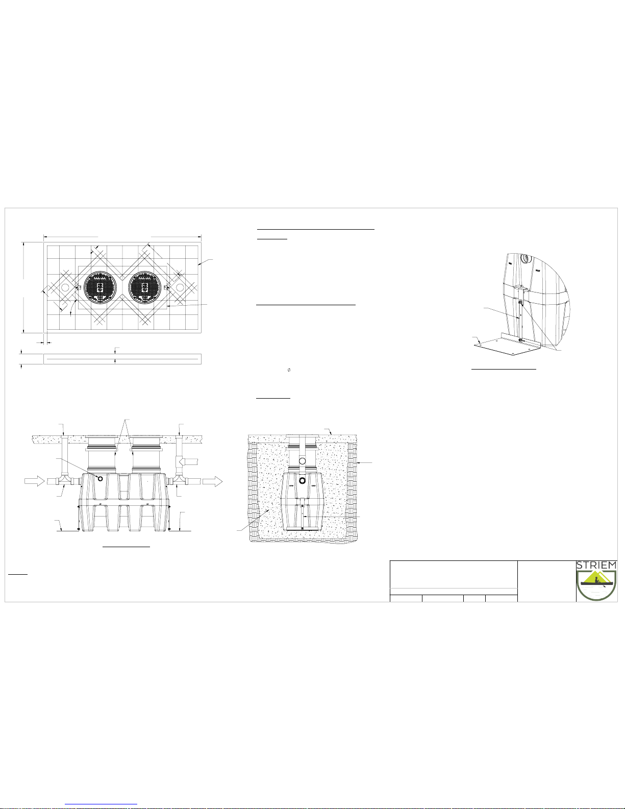
Clean out to grade
on inlet pipe of each
unit (by others)
Clean out to grade
on outlet pipe of each
unit (by others)
Risers to grade
EXCAVATION AND BACKFILL DETAIL
(INTERIOR OR EXTERIOR)
2-Way cleanout
tee (by others)
2-Way cleanout
tee (by others)
SIDE VIEW DETAIL
Optional Anchor kit
see detail
Optional Anchor kit
see detail
VENT
Concrete slab
Native soil
Crushed aggregate
or sand
Optional Anchor kit
see detail
30"
60"
4"
the unit footprint
Concrete Pad
must extend
18" outside
45.00°
2 1/2"
Min.
18" outside the unit footprint
Concrete Pad must extend
8"
4"
Rebar
Finished Grade
Rebar
OS-100
Shown
CONCRETE SLAB DETAIL FOR TRAFFIC LOADING
(INTERIOR OR EXTERIOR)
(OS-100 Shown)
Top View
Elevation View
Stainless steel
Anchor strap
Stainless steel
Anchor plate
Stainless hardware
ANCHOR KIT INSTALLATION DETAIL
Anchor Kit Installation Steps
Slide "Anchor Strap" over tie down point on end wall and
1.
bolt together using provided hardware.
Bolt "Anchor Strap" to "Anchor Plate" using provided hardware
2.
3. Hold down force achieved by backfill weight acting on Anchor Plate.
4. Anchor Plate may be bolted to concrete slab, if required, by using
holes provided in Anchor Plate.
FLOW
FLOW
Striem
3100 Brinkerhoff
Kansas City, KS 66115
Tel: 913-222-1500
Fax: 913-291-0457
www.
striemco.com
Made in the U.S.A
For unit details see specification sheet for selected unit
(Connecting pipe and fittings by others)
INTERIOR OR EXTERIOR BELOW GRADE INSTALLATION INSTRUCTIONS
(OS-35, OS-50, OS-75, OS-100, OS-500)
CONNECTIONS
Connect waste piping to the unit. When connecting OS-75 (2), and OS-500, install
units in series, not parallel.
Connect vent piping to vent connection on sidewall of tank per local code.
BELOW GRADE INSTALLATION INSTRUCTIONS
EXCAVATION
Install unit(s) as close as possible to fixtures being serviced.
1.
Width and length of excavation shall be minimum 12" greater
2.
than the tank on all sides.
Depth of excavation shall be 6" deeper than tank bottom.
3.
Set the tank in well-packed crushed aggregate material
4.
approximately 3/4" size rock, or sand, with no fines. When setting OS-75 (2) and
the OS-500 all units must be level.
Anchor kit is recommended for installations in high water table conditions to
5.
prevent float out. To be determined by specifying engineer. If necessary,
order optional "Anchor Kit". See detail on this sheet.
BACKFILLING & FINISHED CONCRETE SLAB
Preparation of sub grade per geotech recommendations.
1.
Stabilize and compact sub grade to 95% proctor.
2.
Fill tank with water before backfilling to prevent float out during piping installation.
3.
Before backfilling and pouring of slab secure cover(s) and riser/s (if necessary) to the unit(s)
4.
Backfill using crushed aggregate material approximately 3/4" size rock, or sand,
5.
with no fines.
6. Place 6" aggregate base under slab. Aggregate should be 3/4" size rock, or sand, with no fines.
7. Thickness of concrete around cover to be determined by specifying engineer. If traffic
loading is required the concrete slab dimensions shown are for guideline
purposes only.
8. Concrete to be 28 day compressive strength to 4000 PSI.
9. NO. 4 rebar (
1/2") grade 60 steel per ASTM A615: connected with tie wire.
10. Rebar to be 2 1/2" from edge of concrete.
11. Rebar spacing 12" grid. 4" spacing around access openings.
12. All pipe penetrations to be sleeved or have slip connections.
VENT
OS & OCT SERIES INSTALLATION,
OPERATION AND MAINTENANCE GUIDE
ECO:
8/15/18MJREV:
DATE:
DWG BY:
DESCRIPTION:
PROPRIETARY AND CONFIDENTIAL
THE INFORMATION CONTAINED IN THIS DRAWING IS THE SOLE PROPERTY OF
STRIEM, LLC.
ANY REPRODUCTION IN PART OR AS A WHOLE WITHOUT THE WRITTEN PERMISSION OF
STRIEM, LLC.
IS
PROHIBITED.
NOTES:
Striem oil separators are rated and manufactured with an internal flow control system already in
place. They do not require an external flow control system or air intake vent.
Striem oil separators are not to be installed in any other manner except as shown. Consult local
codes for separate trapping requirements, cleanout locations and additional installation instructions.
SHEET NUMBER:
3 of 7

ON-THE-FLOOR DETAIL
(OS-100 SHOWN)
SHOP
FLOW
FLOW
FLOW
FLOW
Max. load
2,500 lb.
OS-25 Shown with riser
Rebar
Riser (sold separately)
16" Max.
VENT
If concrete slab falls within body of unit, reinforce with rebar,
extending 6" beyond footprint of unit to connect main floor slab.
Concrete
Crushed aggregate or sand backfill
Native soil
Striem
3100 Brinkerhoff
Kansas City, KS 66115
Tel: 913-222-1500
Fax: 913-291-0457
www.
striemco.com
Made in the U.S.A
INTERIOR BELOW GRADE INSTALLATION INSTRUCTIONS
(OS-15, OS-25)
EXCAVATION
Install unit(s) as close as possible to fixtures being serviced.
1.
Width and length of excavation shall be minimum 6" greater
2.
than the tank on all sides.
Depth of excavation shall be 6" deeper than tank bottom.
3.
Set the tank in well-packed crushed aggregate #7 backfill material
4.
approximately 3/4" size rock, or sand, with no fines.
CONNECTIONS
Connect waste piping to the unit.
1.
SET OIL DRAW OFF
If unit is ordered with optional oil draw off connection, see sheet 5 for correct settings.
1.
BACKFILLING & FINISHED CONCRETE SLAB
Before backfilling and pouring of slab secure cover(s) to the unit(s).
1.
Backfill using crushed aggregate #7 backfill material approximately 3/4" size rock or sand
2.
with no fines.
3. Place 6" aggregate base under slab.
Note
Models OS-15 and OS-25 cannot be installed flush with floor. A riser must be used for below
grade installations.
INTERIOR ABOVE GRADE INSTALLATION INSTRUCTIONS
(OS-15, OS-25, OS-35, OS-50, OS-75, OS-100, OS-500)
Install unit(s) as close as possible to fixtures/drains being serviced.
CONNECTIONS
Connect waste piping to the unit.
SET OIL DRAW OFF
If unit is ordered with optional oil draw-off connection, see sheet #5 for correct settings.
VENT
OS & OCT SERIES INSTALLATION,
OPERATION AND MAINTENANCE GUIDE
ECO:
8/15/18MJREV:
DATE:
DWG BY:
DESCRIPTION:
PROPRIETARY AND CONFIDENTIAL
THE INFORMATION CONTAINED IN THIS DRAWING IS THE SOLE PROPERTY OF
STRIEM, LLC.
ANY REPRODUCTION IN PART OR AS A WHOLE WITHOUT THE WRITTEN PERMISSION OF
STRIEM, LLC.
IS
PROHIBITED.
NOTES:
Striem oil separators are rated and manufactured with an internal flow control system already in
place. They do not require an external flow control system or air intake vent.
Striem oil separators are not to be installed in any other manner except as shown. Consult local
codes for separate trapping requirements, cleanout locations and additional installation instructions.
SHEET NUMBER:
4 of 7

Striem
3100 Brinkerhoff
Kansas City, KS 66115
Tel: 913-222-1500
Fax: 913-291-0457
www.
striemco.com
Made in the U.S.A
Oil Separator (OS)
Oil Collection Tank (OCT)
FLOW
A A
INLET
OIL DRAW OFF
OUTLET
Spill Line
COMMON VENT
Maximum Oil Capacity
Operating Water Level
Static Water Level
Adjustable Oil
Draw-Off Arm
Oil Separator (OS)
Oil Collection Tank (OCT)
Oil Collection Tank Installation
(OCT-50, OCT-125, OCT-275)
CONNECTIONS
Connect vent pipe and spill line as shown.
1.
Install an additional vent on the outlet pipe of the OS unit.
2.
Adjust Oil Draw-Off arm between 1/4" to 1/2" above operating water line.
3.
INSTALLATION INSTRUCTIONS
Install unit(s) as close as possible to OS Series tank.
1.
OCT tank installation is identical to similar sized OS tanks. See Sheets #2 through #4, and sheets #7
2.
and #8 for TeleGlide installation.
PUMPING FREQUENCY:
Frequency depends on the capacity of the interceptor and the
amount of oil and sediment in the wastewater.
After initial installation, it is recommended that the unit is pumped
every 3 to 4 weeks. Monitor each pumping to establish an adequate
maintenance Striem recommends pumping
frequency not to exceed more than 6 months.
OIL DRAW-OFF (OPTIONAL)
Striem Oil Separators may be ordered with a 1-1/2" draw-off unit consisting
of an adjustable draw-off tube and slip-nut. In order for the Oil Separator to work
properly, the oil draw-off must be adjusted to meet the correct operating
height for the flow of the unit. The oil draw-off unit leads separated oil into an
oil drainage line and collection tank, where it can be taken care of properly
(See OCT Series).
Once the Oil Separator is installed, an operating water level must be established.
Remove covers and run water through separator at maximum flow rate. Move
adjustable draw-off tube between 1/4" to 1/2" above operating water line. If
discharged oil contains water, raise adjustable tube until only oil is being removed.
Draw-off setting must be checked periodically. If draw-off tube is properly set,
water will not draw off with oil.
Slip-nut
Adjustable gravity
draw-off tube
Oil discharge to
collection tank
Exterior wall
of separator
Static water level
Operating water level
OS & OCT SERIES INSTALLATION,
OPERATION AND MAINTENANCE GUIDE
ECO:
8/15/18MJREV:
DATE:
DWG BY:
DESCRIPTION:
PROPRIETARY AND CONFIDENTIAL
THE INFORMATION CONTAINED IN THIS DRAWING IS THE SOLE PROPERTY OF
STRIEM, LLC.
ANY REPRODUCTION IN PART OR AS A WHOLE WITHOUT THE WRITTEN PERMISSION OF
STRIEM, LLC.
IS
PROHIBITED.
NOTES:
Striem oil separators are rated and manufactured with an internal flow control system already in
place. They do not require an external flow control system or air intake vent.
Striem oil separators are not to be installed in any other manner except as shown. Consult local
codes for separate trapping requirements, cleanout locations and additional installation instructions.
SHEET NUMBER:
5 of 7

Striem
3100 Brinkerhoff
Kansas City, KS 66115
Tel: 913-222-1500
Fax: 913-291-0457
www.
striemco.com
Made in the U.S.A
Adapter
Adapter
Cover
Cover
Gasket
Gasket
OS-100
(standard)
Upper clamp
Lower clamp
Lower clamp
Upper clamp
Cut location "C"
LR24
(long riser)
(optional component)
Gasket
Upper Clamp
Lower Clamp
Cut location "B"
SR24
(short riser)
(optional component)
Gasket
Lower Clamp
Upper Clamp
OS-35, OS-50,
OS-75 & OS-100
(standard)
Adapter
Cover
Gasket
Upper clamp
Lower clamp
VENT
FLOW
Finished floor
Figure 1
Riser Height
Adapter
Unit
Figure 2
Adapter
Riser
Riser Height +
Distance from step 5
4"
Cut
Mark
Figure 3
Adapter
Riser
exceed 4"*
Must be at least
2-1/2" and cannot
Gasket
Unit
Riser/Adapter
Upper Clamp
Lower Clamp
Figure 4
*3" for a OS-35 with 4" connections
5. Adjust
adapter
upwards to reach 20" to 22"
6. Adjust
adapter
upwards to reach 35" to 37"
Cut location "A"
Adapter
Cover
Adapter & Cover
(standard component)
Tools included (with base grease interceptor unit(s))
7/16" Nut driver tool/bit
•
Silver permanent marker
•
Tools Needed:
Tape measure
•
Regular or cordless drill with 1/2" chuck
•
Tools needed if Riser(s) require cutting:
Jigsaw or
•
Cordless circular saw or
•
Reciprocating saw
•
Riser Assembly Instructions/Steps:
If unit is to be installed on grade (on-the-floor), there is no need for any adjustments.
1.
Unit is ready to be put into service.
If unit is to be buried: Once unit is set so that the pipe connections line up with
2.
jobsite piping, measure total riser height needed from top of cover to finished
grade. Make sure you include any future tile work, etc. that may be installed
in your finished grade measurements. See figure 1.
Select according riser(s) needed based off Table 1.
3.
If riser(s) is needed, remove cover(s) from adapter and remove adapter from main
4.
unit by loosening upper clamp with included nut driver bit (lower band is factory
set do not adjust or remove). On the floor near the unit, insert adaptor into first riser
until it stops. If needed, insert bottom of first riser into top of second riser until it stops.
You may need to tighten upper clamps during this step to keep risers from shifting.
Adapter and riser(s) should sit level with each other. Removal of cover during this process
will ease assembly.
From the top of the adapter, measure your needed total riser height downward to the
5.
sidewall of the riser. Then, add
5”
(for OS-35 or OS-50) or 6” ( for OS-75, or OS-100).
For example, if you have a OS-100 and need a 15-1/2” extension, you would measure
down from the top of the adapter 21-1/2” (15-1/2” + 6” = 21-1/2”). See Figure 2.
Refer to Table 2, Table 3 or Table 3a to determine if, and where, any cuts need to be made.
6.
If a cut needs to be made, make a circular line around the sidewall of the riser with the
included silver marker at your riser height
+dimension from step 5
. Using a jigsaw, circular
saw or reciprocating saw, cut along your line. Discard/recycle the cutoff scrap.
Whether the riser needs to be cut or not, make another mark with the silver marker on the
7.
sidewall of the riser a distance of
4 INCHES
(3 INCHES for a OS-35 w/ 4” connections) above
the edge just cut. If you did not make a cut (meaning your riser height
+ dimension from
step 5
line was beyond the bottom edge of your riser), still mark the sidewall of the riser
4 INCHES above where your riser height
+ dimension from step 5
line would have been.
DO NOT cut this new line. Once the riser is installed into the main unit, this new line will end
up at the top of the gasket and will aid in re-assembly. See Figure 3.
IMPORTANT: Before the next step:
8.
Make sure both diffusers are installed inside the main unit at the appropriate locations
and check if there needs to be any flow control adjustment on the inlet diffuser. Refer
to sheet 2 of the installation instructions for flow control adjustment.
Refer to sheet 1 of the installation instructions for leak/water testing procedures.
9.
Take riser(s) and adapters apart to reduce the weight during installation. Wipe all sidewalls and
10.
inside of gasket with a damp cloth to remove jobsite dust/debris. Install components into the main
unit starting from the lowest (cut) riser and working your way toward the finished floor level. Upper
clamps at each gasket need to be loosened or removed to aid in assembly. Once riser(s)/adapter
is inserted into gasket, upper clamp can be tightened.
Verify that the bottom of the lowest riser is protruding at least 2-1/2” but no more than 4” into
11.
the main unit from the top of the gasket. Your mark from step 7 should be at the top edge
of the gasket on the main unit. If measurements were made correctly, this should happen
automatically. See figure 4.
If tilting of the adapter is required to be flush with finished grade, it must be done AFTER all
12.
clamps have been tightened with riser(s)/adaptor in a vertical and level position. Tilting is
achieved by using the flexibility of the gasket. If tilting is done before clamps are tightened, a
perfect gasket seal may be compromised. Schier recommends tilting only the adapter versus the
entire riser assembly to make sure your riser height is maintained.
Tighten all clamps to a minimum of 5 and a maximum of 8 ft lbs. of torque. Use the same torque
13.
as you would tighten a rubber no-hub coupling.
The adapter must be adjusted
upward
to achieve certain extension heights. See Table 2,
14.
Table 3 or Table 3a.
If jobsite riser height conditions change after the above steps have been completed, there
15.
may still be room for vertical adjustment in both directions. As long as minimum and maximum
overlaps are maintained (see Figure 4), the adapter/riser(s) can be adjusted/cut as many times
as necessary. Please follow these steps from the beginning to ensure the proper overlaps are
maintained.
1. Adjust
adapter
upwards to reach 22" to 24"
2. Adjust
adapter
upwards to reach 37" to 39"
3. Adjust
adapter
upwards to reach 56" to 58"
4. Adjust
adapter
upwards to reach 70" to 72"
5. For OS-75 , Adaptor will need to be cut short at
location "A" to reach 0"- 3-1/2" due to oprn top
Deffuser.
7. Adjust
adapter
upwards to reach 19" to 21"
8. Adjust
adapter
upwards to reach 34" to 36"
TeleGlide Riser (24 Series) Installation Guidelines
(OS-35, OS-50, OS-75, OS-100)
Call Striem with questions or suggestions @ 1-913-222-1500 Customer Service Hours: 8AM-5PM CST
OS & OCT SERIES INSTALLATION,
OPERATION AND MAINTENANCE GUIDE
ECO:
8/16/18MJREV:
DATE:
DWG BY:
DESCRIPTION:
PROPRIETARY AND CONFIDENTIAL
THE INFORMATION CONTAINED IN THIS DRAWING IS THE SOLE PROPERTY OF
STRIEM, LLC.
ANY REPRODUCTION IN PART OR AS A WHOLE WITHOUT THE WRITTEN PERMISSION OF
STRIEM, LLC.
IS
PROHIBITED.
NOTES:
Striem oil separators are rated and manufactured with an internal flow control system already in
place. They do not require an external flow control system or air intake vent.
Striem oil separators are not to be installed in any other manner except as shown. Consult local
codes for separate trapping requirements, cleanout locations and additional installation instructions.
SHEET NUMBER:
6 of 7

Striem
3100 Brinkerhoff
Kansas City, KS 66115
Tel: 913-222-1500
Fax: 913-291-0457
www.
striemco.com
Made in the U.S.A
OS-15
Cover
(included with
base unit)
Riser Kit
OS-25
VENT
FLOW
Figure 4
Finished floor
Fasten Cover
Install Riser
VENT
FLOW
Figure 1
Remove cover
Install ring / bolts
Finished floor
X"
VENT
FLOW
Figure 2
Finished floor
Install
Riser
Measure
X"
Figure 3
Riser
Mark, cut,
and deburr
Measurement from
Figure 2
Riser
Bolts
Gasketed Ring
SR16 Riser Kit
(Sold Separately)
2-1/8" Min.
VENT
FLOW
Figure 5
16" Max.
VENT
FLOW
Tools included (with riser kit)
Silver permanent marker
•
Tools Needed:
Tape measure
•
Phillips head screwdriver
•
Jigsaw or
•
Cordless circular saw or
•
Reciprocating saw
•
Riser Assembly Instructions/Steps:
If unit is to be buried, you will need a riser kit (sold separately). The 16 Series TeleGlide Riser System for these models
1.
allows riser heights from 2-1/8" above standard unit up to 16". Only ONE riser may be used per base unit to allow sufficient
access to internal serviecable components. See Figure 5.
If more than 16" of riser height is needed, you will need to adjust jobsite requirements OR purchase the next available
2.
model with a 24 Series TeleGlide Riser System which allows taller riser heights.
Once unit is set so that pipe connections line up with jobsite piping, remove cover from unit. Fasten yellow gasketed ring to
3.
unit with hardware provided in separate riser kit. Ring flange with 4 bolt notches faces down against the unit. See Figure 1.
Push riser into ring until it stops (about 1 inch). See Figure 2.
4.
Measure the distance from the top edge of the riser down to the finished floor. Make sure to account for any future tile work
5.
in your measurment. See Figure 2.
Remove riser from ring. Take measurement from step 5 from the BOTTOM of the riser upwards towards the top of the
6.
riser. Mark a line around the riser, and cut with handsaw, jig saw, or reciprocating saw. Remove debris from cut edge with
scraper, utility knife, or gloves. See Figure 3.
Place cut riser back into ring on unit until it stops. Fasten cover from unit into riser with the same 4 bolts from the unit. Unit
7.
is ready to be water tested and backfilled. Install finished floor. See Figure 4.
TeleGlide Riser (16 Series) Installation Guidelines
(OS-15, OS-25)
Minimum and maximum riser heights when units are buried.
OS & OCT SERIES INSTALLATION,
OPERATION AND MAINTENANCE GUIDE
ECO:
8/16/18MJREV:
DATE:
DWG BY:
DESCRIPTION:
PROPRIETARY AND CONFIDENTIAL
THE INFORMATION CONTAINED IN THIS DRAWING IS THE SOLE PROPERTY OF
STRIEM, LLC.
ANY REPRODUCTION IN PART OR AS A WHOLE WITHOUT THE WRITTEN PERMISSION OF
STRIEM, LLC.
IS
PROHIBITED.
NOTES:
Striem oil separators are rated and manufactured with an internal flow control system already in
place. They do not require an external flow control system or air intake vent.
Striem oil separators are not to be installed in any other manner except as shown. Consult local
codes for separate trapping requirements, cleanout locations and additional installation instructions.
SHEET NUMBER:
7 of 7
 Loading...