

Page 1
3505 HUTCHINSON ROAD
U
L
C
US
R
CUMMING, GA 30040-5860, USA
STRIDE™ INDUSTRIAL UNMANAGED ETHERNET SWITCH
8-PORT – DATA SHEET
NN
::
OOTTEE
OR ADDI TONAL PRO DUC T DETAILS, A US ER MANU AL,
F
SE-USER-M, IS AVAILABLE AS A DOWNLAODABLE PDF FILE FROM THE
AA
UUTTOOMMAATTIIOONNDDIIRREECCTT
8 ports
IEEE 802.3, 802.3u, 802.3x
1024 addresses
3.2 Gbps
16 us + frame time (typical)
5 us + frame time (typical)
Redundant Input Terminals
4.0 W
Yes
15,000 watts peak
5,000 watts (10x for 10 uS)
1500 VRMS 1 minute
-10 to +60 °C (+14 to +140 °F),
cold startup at -10 °C (+14 °F)
-40 to +85 °C (-40 to +185 °F),
cold startup at -40 °C (-40 °F)
-40 to +85 °C (-40 to +185 °F)
5 to 95% RH
No corrosive gasses permitted
IEC68-2-6, -27, -32
(Zone 2, Category 3), CE (ATEX)
FCC part 15, ICES-003, EN55022
IEC61326-1
EN50021/EN60079-15 (Zone2)
SE-SW8U
SE-SW8U-WT
Metal case designed
for -40 ° to 85 °C.
Description:
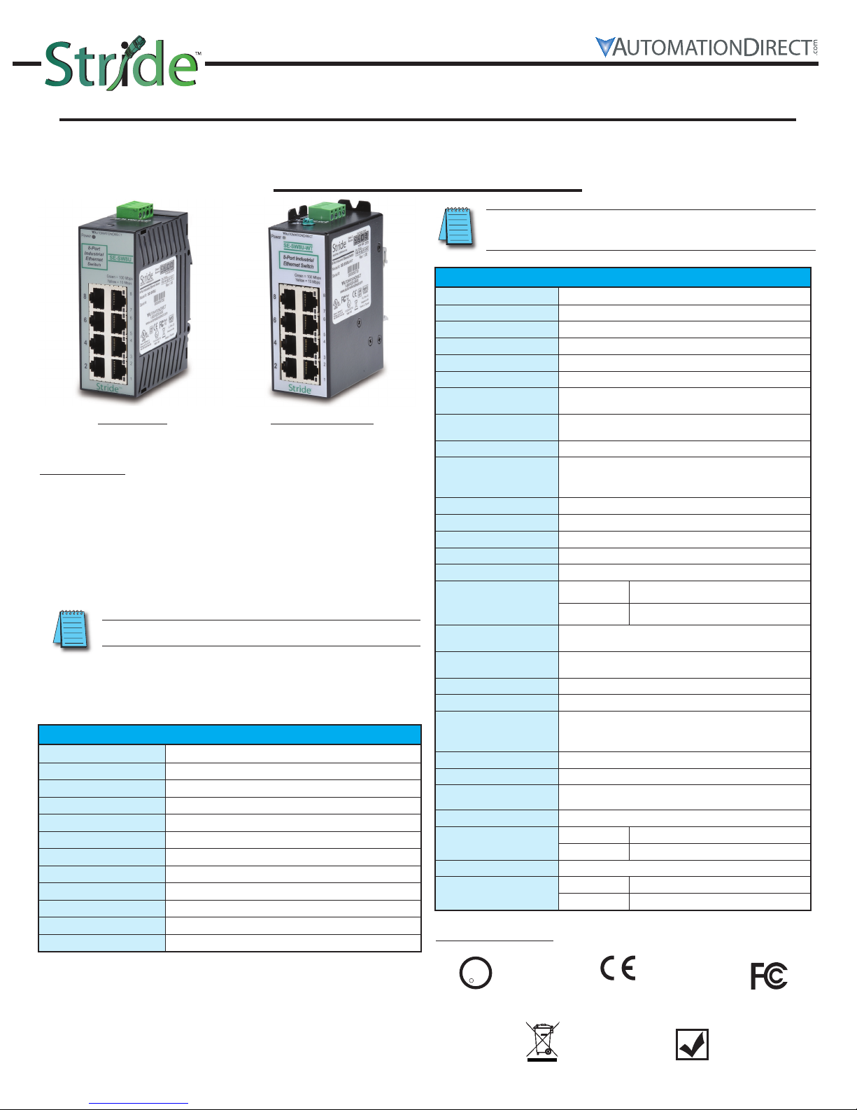
STRIDE SlimLine Industrial Unmanaged Ethernet Switch with eight
10/100BaseT RJ45 Ethernet ports. Redundant power inputs with surge
and spike protection. Auto-crossover. DIN rail mounting. Supports
store & forward wire speed switching and full-duplex with flow control.
UL, CSA (CUL), & CE. The -WT models have a metal case and are
rated for a wider temperature range, from -40 ° to 85 °C.
NN
::
OOTTEE
D
1 - 8 0 0 - 6 3 3 - 0 4 0 5
10/100BaseT ports
Protocols supported
Ethernet compliancy
Auto-crossover
Auto-sensing operation
Auto-negotiating
Auto-polarity
Flow control
Ethernet isolation
Plug and play
Cable requirements
Max. cable distance
SHOWN ON THE BACK OF THIS DATA SHEET.
IMENSIONS, INSTALLATION AND WIRING INFORMATION IS
Copper RJ45 Ports: (10/100BaseT)
Shielded RJ45
All standard IEEE 802.3
IEEE 802.3, 802.3u, 802.3x
Yes, allows you to use straight-through or crossover wired cables
Yes, Full and half duplex
Yes, 10BaseT and 100BaseT
Yes, on the TD and RD pair
Automatic
1500 VRMS 1 minute
Yes
Twisted pair (Cat. 5 or better) (shielded recommended)
100 meters
ONLINE DOCUMENTATION AREA OF THE
Ethernet switch type
Operating mode
Devices supported
Standards
MAC addresses
Memory bandwidth
Latency for
10 Mbps ports
Latency for
100 Mbps ports
Power input
Input power
(typical with all ports
active at 100 Mbps)
Input voltage
Reverse power protection
Transient protection
Spike protection
Ethernet isolation
Operating temperature
range
Storage temperature
range
Humidity
(non-condensing)
Environmental Air
Vibration, shock & freefall
Agency Approvals
EMI emissions
EMC immunity
Hazardous locations
RoHS and WEEE
Packaging and protection
Dimensions (L x W x H)
Weight
Safety Standards:
General Specifications
Store and forward wire speed switching, non-blocking
All IEEE 802.3 compliant devices are supported
10-30 VDC (continuous) - Class 2 Power Supply
SE-SW8U
SE-SW8U-WT
UL/cUL 508, CSA C22 per EN61010-1,
UL/cUL 1604 (Class 1, Div. 2, Groups A, B, C, D),
CSA C 22.2/213 9 per EN50021/EN60079-15
UL1604, CSA C22.2/213 (Class I, Div.2) (file #E200031);
RoHS (Pb free) and WEEE compliant
SE-SW8U UL94VO Lexan, IP30
SE-SW8U-WT Aluminum IP30
See mechanical diagrams for details
SE-SW8U 6 oz (0.17 kg)
SE-SW8U-WT 8 oz (0.23 kg)
WEB
SITE.
w w w . A u t o m a t i o n D i r e c t . c o m
Electrical Safety
1
European
Directives
RoHS
WEEE Compliant RoHS Compliant
US Emissions
Page 2
3.96
[100.6]
1.50
[38.1]
Dia. 0.15 [3.8]
Use for direct
panel mounting
to a flat surface.
1.98
[50.3]
3.26
[82.8]
0.06
[1.5]
Units: inches [mm]
1.98
[50.3]
Snaps to standard
35 mm x 7.5 mm height
DIN rail (EN50022)
Removable
Screw Block,
Phoenix
p/n 1757035
1.01
[25.7]
1.01
[25.7]
8 Port – SE-SW8U
4.35
[110.5]
Dimensions:
Snaps to standard
35 mm x 7.5 mm height
DIN rail (EN50022)
Removable
Screw Block,
Phoenix
p/n 1757035
C
2.25
[57.1]
2.25
[57.1]
Dia. 0.175 [4.4]
Use for direct
panel mounting to
a flat surface with
up to #8 screw.
4.00
[101.6]
0.30
[7.6]
4.35
[110.5]
Removable
for direct panel
mounting
1.50
[3.81]
1.60
[40.6]
Units: inches [mm]
0.80
[20.3]
3.00
[76.2]
0.39
[9.9]
8 Port – SE-SW8U-WT
4.50
[114.3]
0.175
[4.4]
P2 P1
One DC Supply
+
–
Single DC Power
Redundant DC Power
Chassis
GND
(panel)
P2 P1
+
–
+
–
Chassis
GND
(panel)
Dual DC Supplies
1
2
A
B
A
B
C
Installation – DIN Rail Mounting:
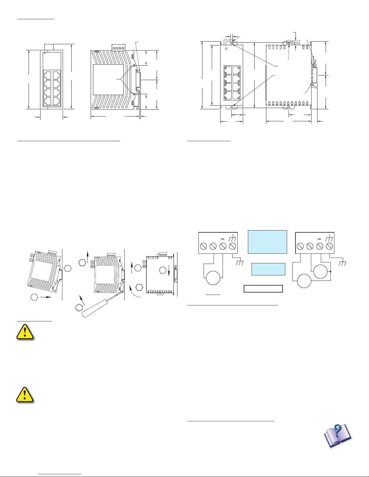
The switch can be snapped onto a standard 35 mm x 7.5 mm height
DIN rail (Standard: CENELEC EN50022) and can be mounted either
vertically or horizontally.
DIN rail mounting steps, plastic and metal case:
1. Hook top back of unit over the DIN rail.
2. Push bottom back onto the DIN rail until it snaps into place.
DIN rail removal steps, plastic case:
A. Insert screwdriver into DIN clip and pry until it releases from the rail.
B. Unhook top of unit from DIN rail.
DIN rail removal steps, metal case:
A. Push the unit down to free the bottom of the DIN rail.
B. Rotate the bottom of the unit away from the DIN rail.
C. Unhook top of unit from DIN rail.
Mounting
Removal, plastic case
Removal, metal case
1 - 8 0 0 - 6 3 3 - 0 4 0 5
WARNING
All power, input and output (I/O) wiring must be in accordance with Class I, Division 2 wiring methods and in
accordance with the authority having jurisdiction.
“This Equipment is Suitable for Use in Class I, Division 2, Groups A, B, C, D or Non-Hazardous Locations Only”.
WARNING – EXPLOSION HAZARD – SUBSTITUTION OF COMPONENTS MAY IMPAIR SUITABILITY FOR CLASS I, DIVISION 2.
WARNING – EXPLOSION HAZARD – WHEN IN HAZARDOUS LOCATIONS, DISCONNECT POWER BEFORE REPLACING OR WIRING UNITS.
WARNING – EXPLOSION HAZARD – DO NOT DISCONNECT EQUIPMENT UNLESS POWER HAS BEEN SWITCHED OFF OR THE AREA IS
KNOWN TO BE NONHAZARDOUS.
WARNING – EXPLOSION HAZARD – IN HAZARDOUS OR POTENTIALLY HAZARDOUS LOCATIONS, DO NOT SEPARATE ANY
PART OF THE UNIT WHEN ENERGIZED. USE THE UNIT FOR INTERNAL CONNECTIONS ONLY.
AVERTISSEMENT – RISQUE D’EXPLOSION – LA SUBSTITUTION DE TOUT COMPOSANT PEUT NUIRE À LA CONFORMITÉ DE CLASSE I,
DIVISION 2.
AVERTISSEMENT – RISQUE D’EXPLOSION – LORSQUE DANS DES ENDROITS DANGEREUX, DÉBRANCHEZ LE CORDON
D'ALIMENTATION AVANT DE REMPLACER OU DE BRANCHER LES MODULES.
AVERTISSEMENT – RISQUE D’AVERTISSEMENT – NE DÉBRANCHEZ PAS L’ÉQUIPEMENT PENDANT QUE LE CIRCUIT EST DIRECT OU À
MOINS QUE L’ENVIRONNEMENT SOIT CONNU POUR ÊTRE LIBRE DE CONCENTRATIONS INFLAMMABLES.
AVERTISSEMENT – RISQUE D’EXPLOSION – DANS LES ENDROITS DANGEREUX OU POTENTIELLEMENT DANGEREUX, NE PAS
SEPARER UNE PARTIE DE L'UNITE SOUS TENSION. SEULEMENT UTILISEZ L'APPAREIL POUR LES CONNEXIONS INTERNES.
Copyright 2014, AutomationDirect.com Incorporated/All Rights Reserved Worldwide
Tout pouvoir, le câblage d’entrée et de sortie (I/O) doivent être conformes aux méthodes de câblage de Classe
I, Division 2 et conformément à l’autorité compétente.
“Cet équipement est adapté pour une utilisation en Classe1, Division 2, Groupes A, B, C et D ou endroits
non-dangereux seulement ”.
Power Wiring:
The switch can be powered from the same DC source that is used to
power your other devices. To maintain the UL508 listing, this must be
a Class 2 power supply. A DC voltage in the range of 10 to 30 VDC
needs to be applied between the P1 (plus) terminal and the Minus
terminal as shown below. The chassis screw terminal should be tied to
panel or chassis ground. To reduce down time resulting from power
loss, the switch can be powered redundantly with a second power
supply as shown below.
A recommended DC power supply is AutomationDirect.com Part
number PSC-24-015.
Maximum power
terminal screw
torque is
5.0 lb-in (0.57Nm).
Wire Size Range
24 – 12 AWG
10-30 VDC, 4.0W
Communication Ports Wiring:
The switch provides connections to standard Ethernet devices such as
PLCs, Ethernet I/O, industrial computers and much more. Use dataquality (not voice-quality) twisted pair cable rated category 5 (or better)
with standard RJ45 connectors. Straight-through or crossover RJ45
cable can be used for all devices the switch is connected to as all the
ports are capable of auto-mdi/mdix-crossover detection.
The RJ45 Ethernet port connector bodies on the switch are metallic
and connected to the Chassis GND terminal. Therefore, shielded cables
may be used to provide further protection. To prevent ground loops,
the cable shield should be tied to the metal connector body at one end
of the cable only. Electrical isolation is also provided on the Ethernet
ports for increased reliability.
Additional Help and Support
• For additional product support, specifications, and
installation, a User Manual, SE-USER-M, is available
as a downloadable PDF file from the Online
Documentation area of www.AutomationDirect.com
• For additional technical support and questions, call our Technical
Support team @ 770-844-4200.
2
w w w . A u t o m a t i o n D i r e c t . c o m
 Loading...