

strex STB-140-04 User Manual

STREX Cell Strain Instrument
Catalog # STB-140-04
User Manual

Contents
Section 1: Main Components......................................................................................... 3
Stretch Unit ................................................................................................................... 3
Control Unit Front Panel ............................................................................................... 4
Control Unit Back Panel ............................................................................................... 4
Silicone Strain Chamber ............................................................................................... 5
Section 2: Use of the Cell Strain Instrument ................................................................ 6
Preparation of Cell Strain Instrument............................................................................ 6
System Operation .....................................................................................
Culturing Cells in the Silicone Chambers……………………………
............................... 6
............................... 7
Preparation of Silicone Chambers................................................................................. 8
Section 3: Strain Parameters……………………………………………………..…………10
Section 4: FAQ ………………………………………………………………..................……11
Section 5: References .................................................................................................. 13
Section 6: Safety Instructions ..................................................................................... 15
Section 7: Warranty ...................................................................................................... 18
2
Section 1: Main Components
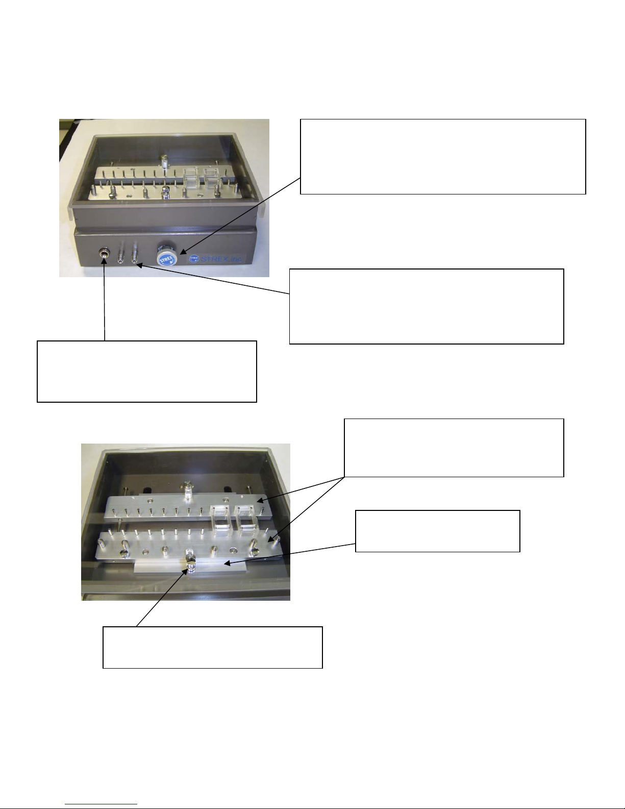
Stretch Unit
Chamber length adjusting knob:
Use the knob to adjust the distance of chamber
brackets to maintain tension on the chamber. The
bottom of the chamber should be taut.
System coolant inlet and outlet valves:
Be sure to supply cool water when in operation.
Failure to do so may lead to overheating inside the
incubator or motor burnout.
Connectors:
Use Connector Cable to connect Control
Unit to Stretch Unit
Alignment Pins:
Holds Strain Chamber Brackets in place
Strain Chamber Brackets:
Each chamber is mounted on four pins,
two pins on each bracket.
Mounting Stage:
Brackets sit on top of the stage
3
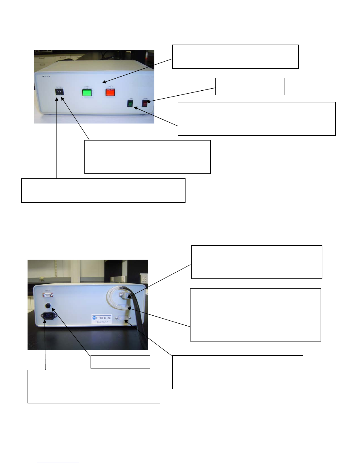
Control Unit Front Panel
Fuse case cover
Strain Ratio:
Use upper and lower buttons to increase
and decrease stretch ratio
Strain Frequency Selector:
Use upper and lower buttons to adjust cycle frequency.
Start and Stop Button:
Use to start or stop the stretching action.
Main Power Switch
Water Pump Switch:
Use to turn on and off the pump that circulates water
to cool the motor.
Control Unit Back Panel
Power Cable Outlet for 110 Volts:
Use the Power Cable to connect the Control
Unit to a power source.
Control Connector:
This cable supplies electricity from the
Control Unit to the Stretch Unit.
System coolant inlet & outlet valves:
Be sure to supply cool water when in
operation. Failure to do so may lead to
overheating inside the incubator or motor
burnout.
Reservoir coolant inlet & outlet valves:
Attach a large flask or similar type of
reservoir filled with cold water.
4

Silicone Strain Chamber (ST-CH-04.0)
20mm x 20mm x 10mm
40m
Chamber Dimensions
Chamber membrane
thickness = 0.1mm
31m
10m
18m
4 places for pins
25m
5

Section 2: Use of the Cell Strain Instrument
Preparation of the Cell Strain Instrument
Before using the Cell Strain Instrument, sterilize the unit — especially the chamber mounting area
— using ethanol-immersed swabs.
System Operation
The STREX Cell Strain System needs to be water cooled when in operation. Without
cooling, the maximum run time for the continuous operation of the motor is only 10
minutes. For longer operation, water cooling is essential. Also, please note that, when operating
the unit in an incubator, the temperature inside the unit will be elevated so it is particularly important
to ensure the cooling system is employed in this environment.
Set up the Strain and Control Unit
1. Set up the cooling system by using the Connector Cable. The Connector Cable supplies
electricity and cold water from the Control Unit to the Stretch Unit. One end of the Cable has 3
plugs of which 2 are identical metal plugs. This end of the Cable attaches to the front of the
Stretch Unit. The 2 identical metal plugs are plugged into the System Coolant Inlet and Outlet
Valves (see Section 1). To release the metal plugs from the Stretch Unit, push backward on
the outer metal rings around the valves. The single, larger black plug supplies electricity to the
Stretch Unit – this plug has to be in the correct orientation to fit properly.
The other end of the Connector Cable has 2 exposed latex tubes which fit onto the System
Coolant Inlet and Outlet Valves on the back panel of the Control Unit. The Cable’s square
shaped plug fits the motor outlet just above the coolant valves.
To circulate cool water throughout the system, use latex tubing to attach a large reservoir of
cold water to the Reservoir Coolant Inlet and Outlet Valves on the back panel of the Control
Unit. The water in the reservoir can be kept cool by placing the reservoir on ice.
2. Use the Power Cable to connect the Control Unit to a 110 volt power source.
3. Turn on the Main Power Switch and Water Pump Switch on the Control Unit. The Switches
will light up.
4. Press the START button to ensure that the strain chamber bracket moves correctly. The Start
Button light will flash when the instrument is stretching.
5. Press the STOP button to ensure that the strain chamber bracket stops moving. The Stop
Button will light up.
6
 Loading...