

Stress-Tek VULCAN ON-BOARD SCALES, V600 Owner's Manual

CONTENTS 1
V600 OWNER’S MANUAL
Table of Contents
V600 MENU TREE.................................................................................................5
V600 BASIC REFUSE SYSTEM SETUP.....................................................................6
1.0 V
ULCAN SINGLE LINE (VSL) TECHNOLOGY, V600 ELECTRONICS SYSTEM........7
1.1 Load Cells And Air Sensors...............................................................................10
1.2 VSL Vulcoders...................................................................................................11
1.3 V600 Meter........................................................................................................11
1.4 Explanation of Meter Channels..........................................................................12
1.5 Electronics Installation.......................................................................................13
2.0 V600 METER OPERATION............................................................................17
2.1 Power / Menu Button Operation ........................................................................17
2.1.1 Powering The Meter On / Off..................................................................17
2.1.2 Entering And Exiting The Meter Program Menu .....................................17
2.2 Arrow Buttons Operation ...................................................................................18
2.2.1 Changing Display Intensity .....................................................................18
2.2.2 Increase / Decrease Meter Program Settings.........................................18
2.3 Cycle Button Operation......................................................................................19
2.3.1 Locking The Meter On A Particular Channel...........................................19
2.3.2 Scroll Through The Meter Program Menu Functions..............................19
2.4 Enter Button Operation......................................................................................20
2.4.1 Selects / Enters Program Menu Items....................................................20
2.4.2 Stores Newly Adjusted Meter Settings.................................................... 20
2.4.3 Displays Time and Date..........................................................................20
2.4.4 Prints A Weight Ticket ............................................................................20
2.5 Tare / Zero Button Operation.............................................................................21
2.5.1 Zeroes Meter Values ..............................................................................21
2.5.2 Zeroes Meter Display In The Pick-up / Delivery Mode............................21
2.5.3 Displays Gross Weight In The Net And Pick-up / Delivery Modes..........21
June 21, 2006 VULCAN ON-BOARD SCALES 1-800-237-0022 Doc. 44-10032-001 Rev. C
© STRESS-TEK, INC. 2006

2 CONTENTS
2.6 Vulcoder Updating.............................................................................................22
3.0 V600 - PROGRAM MENU (SYSTEM SETUP) ...................................................23
3.1 Entering The Program Menu .............................................................................23
3.2 Entering The Configure System Menu...............................................................24
3.2.1 Configure The Weight Mode (Gross, Net, Or Pick-Up)...........................25
3.2.2 Configure The Display Code...................................................................26
3.2.3 Configure The Set Points........................................................................28
3.2.3A Configure Relay 1 .....................................................................29
3.2.3B Configure Relay 2 .....................................................................31
3.2.3C Configure Delta Weight.............................................................32
3.2.3D Configure On Time....................................................................33
3.2.4 Configure The Channel Cycle Time........................................................35
3.2.5 Configure The RS232 Port ..................................................................... 36
3.2.6 Configure The Print Headers..................................................................37
3.2.7 Configure The Date ................................................................................39
3.2.8 Configure The Time................................................................................41
3.2.9 Configure The Scale ID ..........................................................................42
3.2.10 Configure The Lock (Tare and Cal Lockout)........................................... 43
3.2.11 Exiting The Configure System Menu ......................................................44
3.3 Entering The Setup / Calibrate Menu ................................................................44
3.3.1 Setting The Tare Weight.........................................................................44
3.3.2 Setting The Cal Number.........................................................................46
3.3.3 Setting The Cal Weight...........................................................................47
3.3.4 Setting The Post Calibration...................................................................49
3.3.5 Setting The Grad Size ............................................................................51
3.3.6 Setting The Units (Lb or Kg)...................................................................51
3.3.7 Setting The Auto Zero Tracking Range ..................................................52
3.3.8 Setting The Sample Size.......................................................................53
3.3.9 Exiting The Configure System Menu ......................................................55
3.4 Sequencing Channels .......................................................................................55
3.4.1 Manual Sequencing................................................................................56
3.5 System Test Menu.............................................................................................57
June 21, 2006 VULCAN ON-BOARD SCALES 1-800-237-0022 Doc. 44-10032-001 Rev. C
© STRESS-TEK, INC. 2006

CONTENTS 3
3.5.1 Test Keypad............................................................................................58
3.5.2 Test LED’s..............................................................................................58
3.5.3 Test Memory...........................................................................................59
3.5.4 Test VSL Comm .....................................................................................60
3.5.5 Test L / C Offset......................................................................................61
3.6 Exiting The Program Menu................................................................................62
4.0 V600 CALIBRATION.....................................................................................63
4.1 Weight Measuring Methods...............................................................................63
4.1.1 Gross Vehicle Weight.............................................................................64
4.1.2 Net Payload Weight................................................................................64
4.2 Procedure For Entering Tare Weights...............................................................64
4.2.1 Entering Tare Weight For A Typical 2 - Channel, Truck & Trailer
System....................................................................................................64
4.2.2 Entering Tare Weight For A Typical Short Logger System.....................66
4.2.3 Entering Tare Weight For A Typical Refuse System...............................68
4.3 Procedure For Entering Starting Calibration Numbers.......................................69
4.4 Fine Tuning The Calibration Number For Gross Vehicle Weight Method
When Only One Channel Per Truck Or Trailer Is Used .....................................71
4.5 Fine Tuning The Calibration Number For Gross Vehicle Weight And Net
Payload Weight Methods When More Than One Channel Is Used Per Truck
Or Trailer............................................................................................................74
5.0 MAINTENANCE.............................................................................................79
5.1 Driver's Daily Vehicle Inspection........................................................................79
5.2 Preventative Maintenance And Vulcan Torque Specifications...........................80
6.0 TROUBLESHOOTING.....................................................................................87
6.1 Vulcan Check-out Box.......................................................................................88
6.2 Load Cell Evaluation Tests................................................................................89
6.2.1 Leakage Test Procedure ........................................................................89
6.2.2 Tare Test Procedure...............................................................................90
6.2.3 Resistance Test Procedure.....................................................................93
June 21, 2006 VULCAN ON-BOARD SCALES 1-800-237-0022 Doc. 44-10032-001 Rev. C
© STRESS-TEK, INC. 2006

4 CONTENTS
6.3 V600 Meter Error Codes....................................................................................94
6.3.1 Err 01......................................................................................................94
6.3.2 Err 02......................................................................................................94
6.3.3 Err 03......................................................................................................95
6.3.4 Err 04......................................................................................................95
6.3.5 Err 05......................................................................................................96
6.3.6 Err 06......................................................................................................96
6.3.7 Err 07......................................................................................................97
6.3.8 Err 08......................................................................................................97
6.3.9 Err 09......................................................................................................98
6.3.10 Err 10......................................................................................................98
6.3.11 Err 11......................................................................................................98
6.4 System Malfunctions .........................................................................................99
6.4.1 No Indicator Display Or Function Lights .................................................99
6.4.2 Unable To Enter Tare Or Calibration Numbers.....................................100
6.4.3 Meter Reading Drifts Or Wanders With Time .......................................100
6.4.4 Meter Reading Does Not Change When Truck Is Being Loaded..........102
6.4.5 Meter Stops Powering Up After Displaying All Digits............................102
6.4.6 Meter Displays LO-LO..........................................................................103
6.5 Troubleshooting Worksheet.............................................................................106
6.6 Troubleshooting Assistance And Replacement Parts......................................108
7.0 APPENDIX.................................................................................................109
7.1 Starting Calibration Numbers...........................................................................110
7.2 System Specifications .....................................................................................111
7.3 Assistance In Fine Tuning Your Scale System (Primarily For Two Channels
On One Truck Application Only)......................................................................112
7.4 Keeping Records.............................................................................................114
June 21, 2006 VULCAN ON-BOARD SCALES 1-800-237-0022 Doc. 44-10032-001 Rev. C
© STRESS-TEK, INC. 2006
V600 MENU TREE 5
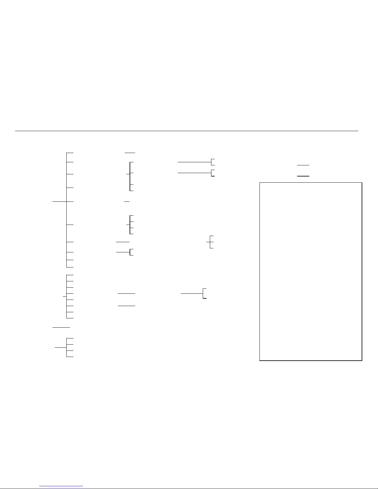
V600 MENU TREE
CONF: WT. MODE
CONF: DISP CODE
CONF: SET POINTS
CONF: CYCLE TIME
CONF: RS232 PORT
CONF: PRINT HDRS
CONF: DATE
CONF: TIME
CONF: SCALE ID
CONF: LOCK
SET: TARE WEIGHT
SET: CAL NUMBER
SET: CAL WEIGHT
SET: POST CAL
SET: GRAD SIZE
SET: UNITS
SET: AZT RANGE
SET: SAMPLE SIZE
START SEQUENCING
TEST: KEYPAD
TEST: LEDs
TEST: MEMORY
TEST: VSL COMM
WT MODE: [GROSS] [NET] [P/D]
CONF: RELAY 1
CONF: RELAY 2
CONF: DELTA WT.
CONF: ON TIME
FORMAT: [NONE] [PRINT] [WEIGHT] [OBC]
HEADER LINE 1
HEADER LINE 2
HEADER LINE 3
HEADER LINE 4
FORM: [MM/DD/YY] [DD/MM/YY]
CHANGE: HOURS
CHANGE: MINUTES
CH X POST CAL
UNITS: [LBS] [KGS]
R1: [OFF]
R1: [LOCKED ONLY] [CH A] ... etc
R2: [LOCKED ONLY] [CH A] ... etc
R2: [OFF]
R1: ENT WT LIMIT
R2: ENT WT LIMIT
CHANGE: YEAR
CHANGE: MONTH
CHANGE: DAY
V600 GROSS WT
ACTUAL GROSS WT
CONFIGURE
SYSTEM
SEQUENCE
CHANNELS
SYSTEM TEST
TE
[SCRBRD3] [SCRBRD6]
SETUP/CALIBRA
V600 Menu Operation
1. To enter menu mode, press the
PWR/MENU button once.
2. To cycle through the menu options,
press the CYCLE button.
3. To select one of the menu options
or select a submenu, press the
ENTER button.
4. To change a value (such as Tare
Weight, Cal Number, etc.) which
appears in the upper display
window, or option values (such as
Wt Mode, RS-232 Port Format, etc)
which appear in brackets in the
lower display, press the UP or
DOWN arrow buttons.
5. To reset a value to zero, press the
TARE/ZERO button. Note: this
does not work for all values
6. To accept a value press the
ENTER button.
7. To cancel a selection or return to
the previous menu level, press the
PWR/MENU button.
June 21, 2006 VULCAN ON-BOARD SCALES 1-800-237-0022 Doc. 44-10032-001 Rev. C
© STRESS-TEK, INC. 2006

6 V600 BASIC REFUSE SYSTEM SETUP
V600 BASIC REFUSE SYSTEM SETUP
1. Enter the Program Menu by pressing the PWR/MENU button after the meter has finished its start up routine, Section 3.1.
2. Configure System will be displayed on the smaller display. Press the ENTER button to enter the Configure System Menu, Section 3.2.
3. Configure the Weight Mode: Press the ENTER button to select the CONF: WT. MODE Menu. Most users will set the weight mode to the
Pickup/Deliver Mode by pressing the UP or DOWN ARROW buttons until [P/D] is displayed. Press the ENTER button to save the desired
selection. See Section 3.2.1 for more details.
4. Set the vehicle Tare Weight: Press the PWR/MENU button to return to the Configure System Menu. Press the CYCLE button to advance to the
Setup/Calibrate Menu. Press the ENTER button to enter the Setup/Calibrate Menu. Press the ENTER button to select the SET: TARE
WEIGHT Menu. Press either the UP or DOWN ARROW buttons to adjust the number to the desired Tare Weight. Most users will set the Tare
Weight to zero to monitor net payload. Press the ENTER button to save the desired Tare Weight. See Section 3.3.1 for more details.
5. Set the Grad Size: Press the CYCLE button to advance to the SET: GRAD SIZE Menu is displayed. Press the ENTER button to enter the SET:
GRAD SIZE Menu. Press either the UP or DOWN ARROW buttons to adjust the desired Grad Size. Most users find that leaving the Grad Size
set to 50 works well without being too sensitive. Press the ENTER button to save the desired Grad Size. See section 3.3.5 for more details.
6. Set the Auto Zero Tracking Range to Zero: Press the CYCLE button to advance to the SET: AZT RANGE Menu. Press the ENTER button to
enter the SET: AZT RANGE Menu. Press either the UP or DOWN ARROW buttons to adjust the AZT Range to zero. Press the ENTER button
to save the desired AZT Range. See section 3.3.7 for more details.
7. Exit the Program Menu: Press the PWR/MENU button until the display returns to the normal operating mode. See section 3.6 for more details.
June 21, 2006 VULCAN ON-BOARD SCALES 1-800-237-0022 Doc. 44-10032-001 Rev. C
© STRESS-TEK, INC. 2006
CHAPTER 1 7
V
C H A P T E R 1 . 0
VULCAN SINGLE LINE (VSL) TECHNOLOGY
V600 ELECTRONICS SYSTEM
Vulcan On-Board Scales can be installed on all types of vehicles including, hook lifts, logging trucks,
flatbed trailers, chip trailers, front loaders, rear loaders, side loaders, roll-offs, transfer trailers, and
many other commercial vehicles requiring scales. Axle group weights, payload weights, gross vehicle
weights, and individual pick-up and drop-off weights can be measured using the Vulcan On-Board
Scale System.
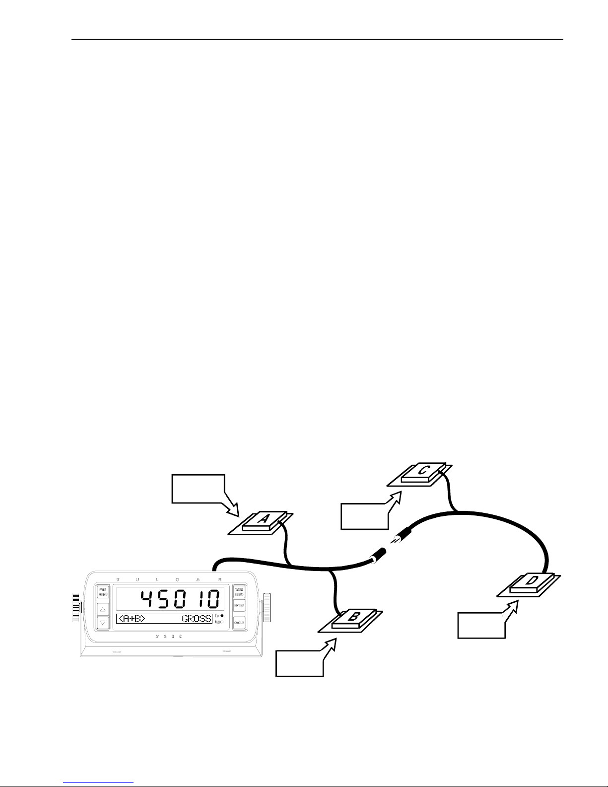
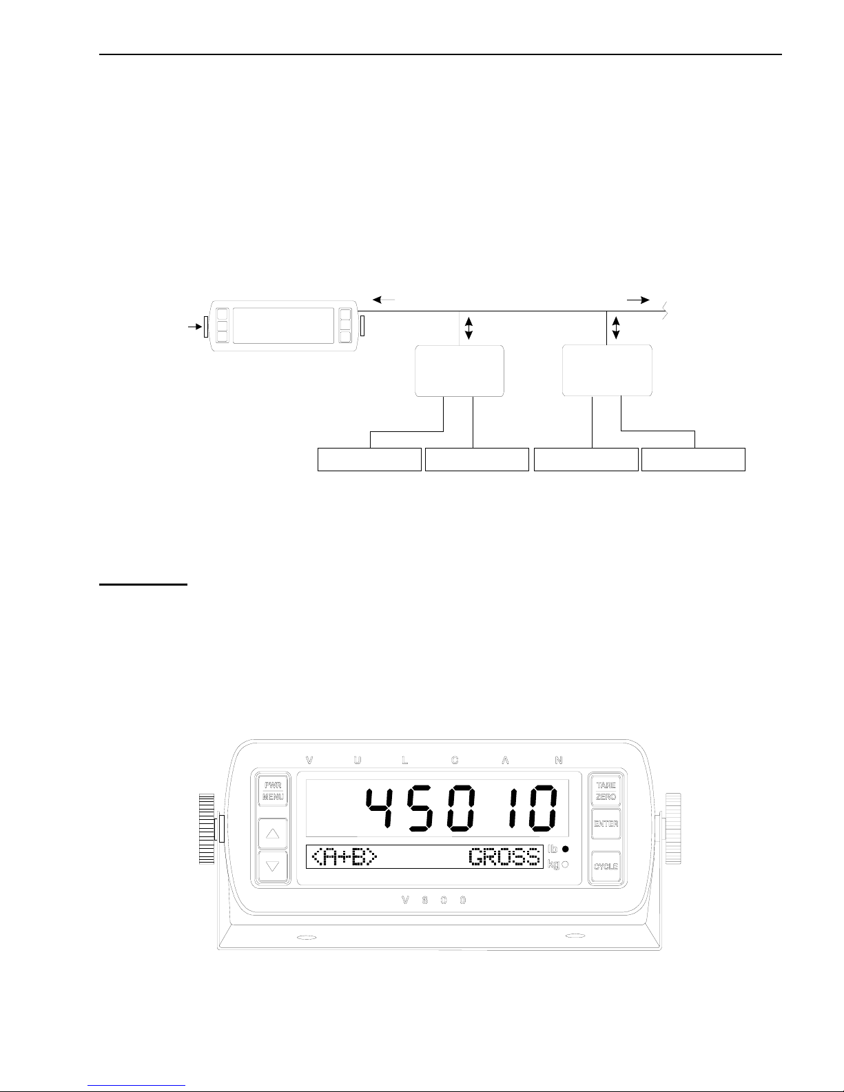
The Vulcan On-Board Scale System consists of:
• Load Cells or Air Sensors - to sense load or air pressure.
• VSL Vulcoders - to convert the signals from the sensors to weight and communicate with
the meter.
• V600 Meter - to display the weights and run the scale system.
The number of VSL Vulcoders needed depends on the number of channels required. The number and
type of load cells needed depends on the truck’s configuration, such as length, type of suspension, load
capacity, etc. Only one V600 Meter is required per truck.
The new Vulcan Single Line (VSL) technology is a revolutionary way that the V600 Meter
communicates with each VSL Vulcoder. VSL technology uses a single 2-wire cable to provide the
communications between the meter and VSL Vulcoders. The single 2-wire communication cable
sends power and set-up data to each VSL Vulcoder while receiving weight data from each VSL
Vulcoder.
VSL
LOAD CELL
OR
AIR SENSOR
LOAD CELL
OR
AIR SENSOR
VULCODER
T
R
AI
L
E
R
June 21, 2006 VULCAN ON-BOARD SCALES 1-800-237-0022 Doc. 44-10032-001 Rev. C
VSL
VULCODER
K
C
U
R
T
VSL
VULCODER
LOAD CELL
OR
AIR SENSOR
ULCAN SINGLE LINE (VSL)
Figure 1-A: VSL Single Line (VSL)
4-Channel System Example
© STRESS-TEK, INC. 2006
LOAD CELL
OR
AIR SENSOR
VSL
VULCODER

8 CHAPTER 1
R
R
4 EACH
V
V
= V600 ME TER
= VSL VULCODER
V
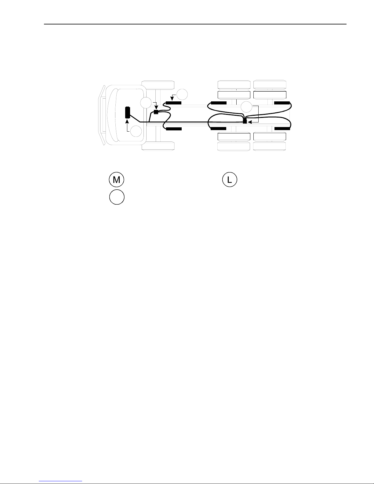
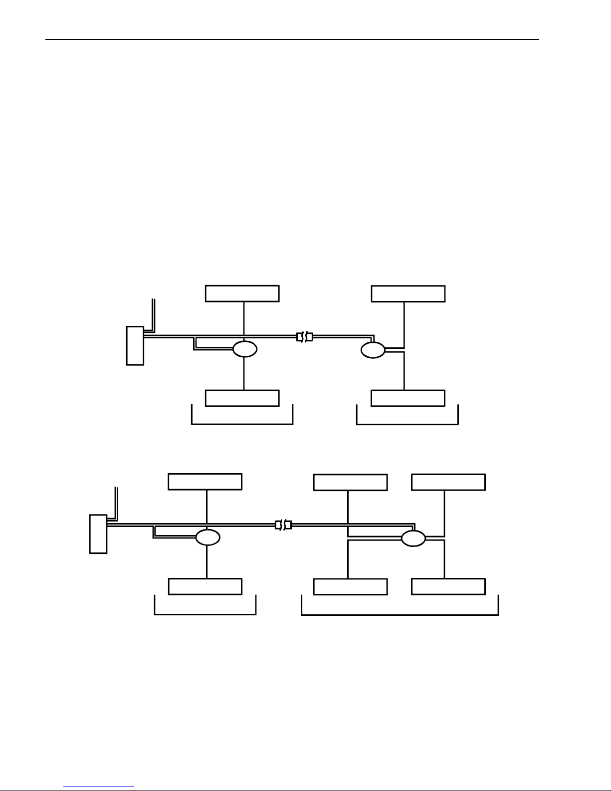
Figure 1-B: Example - VSL Long Logger System
(Truck: 1-channel, Trailer: 1-channel)
V
L
4 EACH
C
= LOAD C E LL
TRUCK / TRAILER
=
C
CONNECTO
M
= V600 ME T ER
= VSL VULCODER
V
Figure 1-C. Example - VSL Short Logger System
(Truck: 2-channels, Trailer (not shown): 2-channels)
June 21, 2006 VULCAN ON-BOARD SCALES 1-800-237-0022 Doc. 44-10032-001 Rev. C
= LOAD CELL
=
C
© STRESS-TEK, INC. 2006
V
C
TRUCK / TRAILER
CONNECTO
CHAPTER 1 9
L
6 EACH
V
M
V
= V600 METER
= VSL VULCODER
V
= LOAD CELL
Figure 1-D. Example - VSL Refuse System with 6 Load Cells
(Truck: 2-channels)
June 21, 2006 VULCAN ON-BOARD SCALES 1-800-237-0022 Doc. 44-10032-001 Rev. C
© STRESS-TEK, INC. 2006
10 CHAPTER 1
1.1 LOAD CELLS AND AIR SENSORS
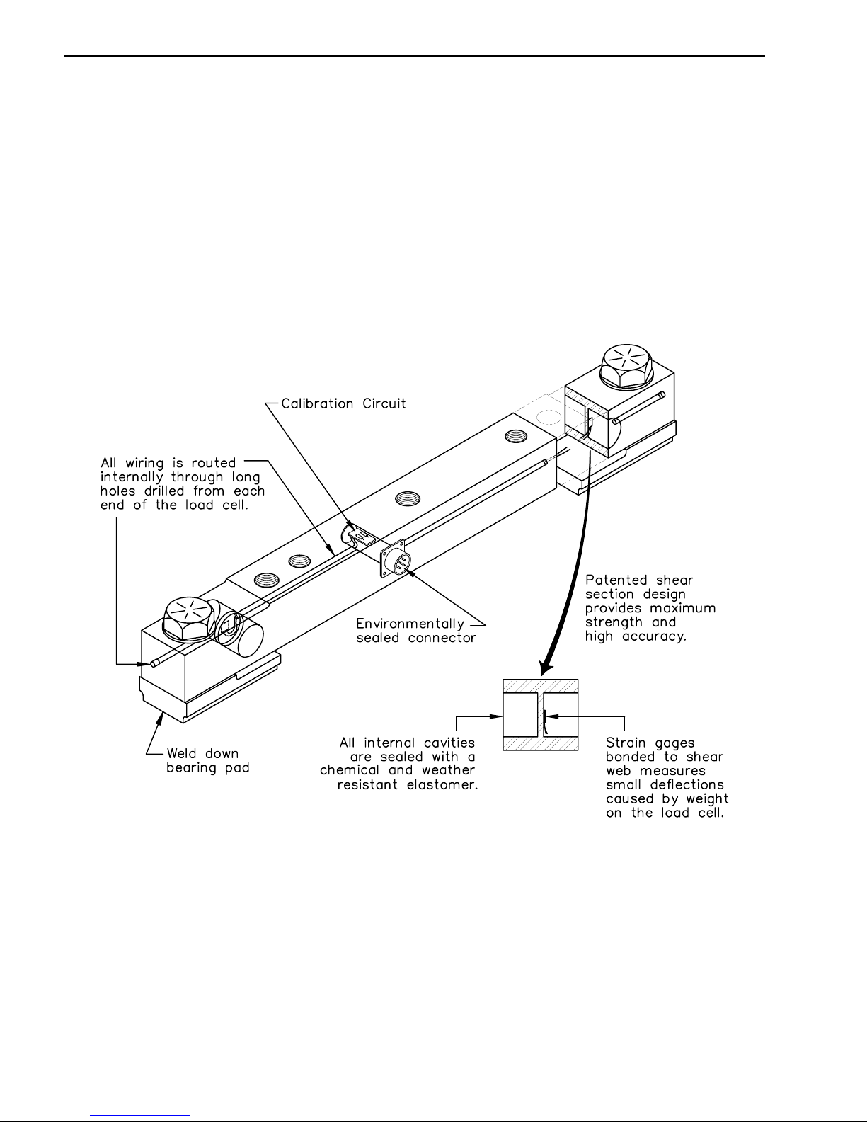
Vulcan load cells and air sensors are machined from solid blocks of high strength steel. The Strain
gages are bonded inside the load cell or air sensor to sense extremely small dimensional changes in the
material. A strain gage is a precision electrical resistance element. When force is applied to these
sensors, the strain gages stretch or compress, causing a change in output signal voltage. This signal
voltage is measured by the VSL Vulcoder and then used to determine weight.
Example: Vulcan Super - Beam Load Cell
Figure 1-E: Vulcan Super - Beam Load Cell
(Covered by one or more of the following patents:
US Patent RE. 35,301, 4,459,863
June 21, 2006 VULCAN ON-BOARD SCALES 1-800-237-0022 Doc. 44-10032-001 Rev. C
Canadian Patent 1,245,677)
© STRESS-TEK, INC. 2006
CHAPTER 1 11
1.2 VSL VULCODERS
The VSL Vulcoder is specifically designed to be used with the V600 meter. The functions of the VSL
Vulcoder are to supply power to the load cells or air sensors and receive the analog voltage signal
from the load cells or air sensors. A computer inside the VSL Vulcoder then calculates the weight
based on the calibration values, the “Tare Weight” and the “Cal” number for that particular channel,
which are stored in its memory. When the meter requests weight from a channel, the proper VSL
Vulcoder will respond and send the weight information back to the meter. All VSL Vulcoders connect
to the same single 2-wire cable. Any VSL equipped trailer can be plugged into any truck with a V600
meter and be immediately identified and read properly.
10.5-29 Vdc
POWER & 2-WAY COMM UN IC ATION S
WEIGHT lb/kg
TO OTHER
VSL VULCODERS
VSL VULCOD ER
AMPLIFIES,
COMPUTES &
STORES DATA
V600 METER
LOAD CELL
VSL VULCODER
AMPLIFIES,
COMPUTES &
STORES DATA
LOAD CELL LOAD CELL LOAD CELL
Figure 1-F: Vulcan Electronics Diagram
1.3 V600 METER
Application: For vehicle combinations with one to six channels of weight sensing. The V600 Meter
provides a high visibility display and the ability to easily read different trailers.
The V600 Meter uses VSL technology to power and communicate with VSL Vulcoders on a single
2-wire cable. The meter requests weight information from the different Vulcoders. It then displays
individual channel weights and total weight as requested by the operator. The weight can be displayed
in pounds or kilograms. The meter also transfers all setup and calibration information for up to six
independent channels (A, B, C, D, E, and F) into the VSL Vulcoder, where it is stored.
June 21, 2006 VULCAN ON-BOARD SCALES 1-800-237-0022 Doc. 44-10032-001 Rev. C
Figure 1-G: V600 Meter
© STRESS-TEK, INC. 2006
12 CHAPTER 1
1.4 EXPLANATION OF METER CHANNELS
The V600 meter can display information on up to six channels: A, B, C, D, E, and F. There is a VSL
Vulcoder for each channel. The number of channels is based on the number of load cells and their
grouping. For example, a trailer could have as many as four load cells per channel. The display code
tells the meter what channels to scan. For more information on how to select the meter display code,
refer to Section 3.2.2 “Configure The Display Code”.
Refuse or Logging Truck Applications:
Typically, a refuse or logging truck application usually requires only one or two meter channels, A, or
A and B. Channel A usually represents the truck or front load cells regardless of the number of load
cells connected to the VSL Vulcoder. Channel B usually represents the trailer or rear load cells. The
total weight for both the front and rear load cells is represented on Channel A+B.
10.5 - 29 Vdc
LOAD CELL
LOAD CELL
METER
10.5 - 29 Vdc
METER
VSL VU LCOD ER
LOAD CELL
CHANNEL A
LOAD CELL
VSL VU LCODER VSL VU LCODER
CHANNEL A
VSL VU LCODER
LOAD CELL
CHANNEL B
LOAD CELL LOAD CELL
LOAD CELLLOAD CELL
CHANNEL B
LOAD CELL
Figure 1-H: Vulcan 4 and 6 Cell System Configurations
June 21, 2006 VULCAN ON-BOARD SCALES 1-800-237-0022 Doc. 44-10032-001 Rev. C
© STRESS-TEK, INC. 2006

CHAPTER 1 13
1.5 ELECTRONICS INSTALLATION
1. Tape the VSL Vulcoder connectors prior to routing the cabling to avoid contamination. Mount
the VSL Vulcoders on the inside of the truck frame rail or next to a structural member. The
VSL Vulcoder mounting surface must be in an area protected from road and hauling debris.
2. Route the black cable to the load cells. (Do not trim the black cable to length).
3. Important: Check the connectors to make sure they are clean and dry. Do not get moisture,
contact cleaner, or any other substance inside of the connectors.
4. Check the load cell connector coming from the VSL Vulcoder for an O-ring. Attach the black
cable connectors to the bulkhead connectors on the load cells. Make sure they are finger tight
plus an additional 1/8 of a turn more with channel lock pliers. The additional tightening is
necessary to compress the O-ring. This prevents scale errors which can occur from moisture
entering into the load cell connector. Caution: Do not over tighten the connectors as this can
damage them.
5. Route the single 2-wire orange VSL Vulcoder cable from the meter in the cab to the last VSL
Vulcoder in the system. Be sure to route the cable to the meter and do not trim any excess
wire off at the meter. Trim off the excess cable to approximately 1' - 2' of extra orange cable at
the location of the VSL Vulcoder splice to allow for the splice. Note: On a truck-to-trailer
connection, these wires may be routed using the existing truck-to-trailer wire harness if two
unused ungrounded wires are available. Additionally, you may follow the existing wire
harness and use a separate connector of your choice between the truck and trailer. If using the
separate connector, for the best and most reliable connection, connect each color wire to two
pin connections. For example, connect the green wire to the top two pins of a 4-pin truck-totrailer connector, and the white wires to the bottom two pins.
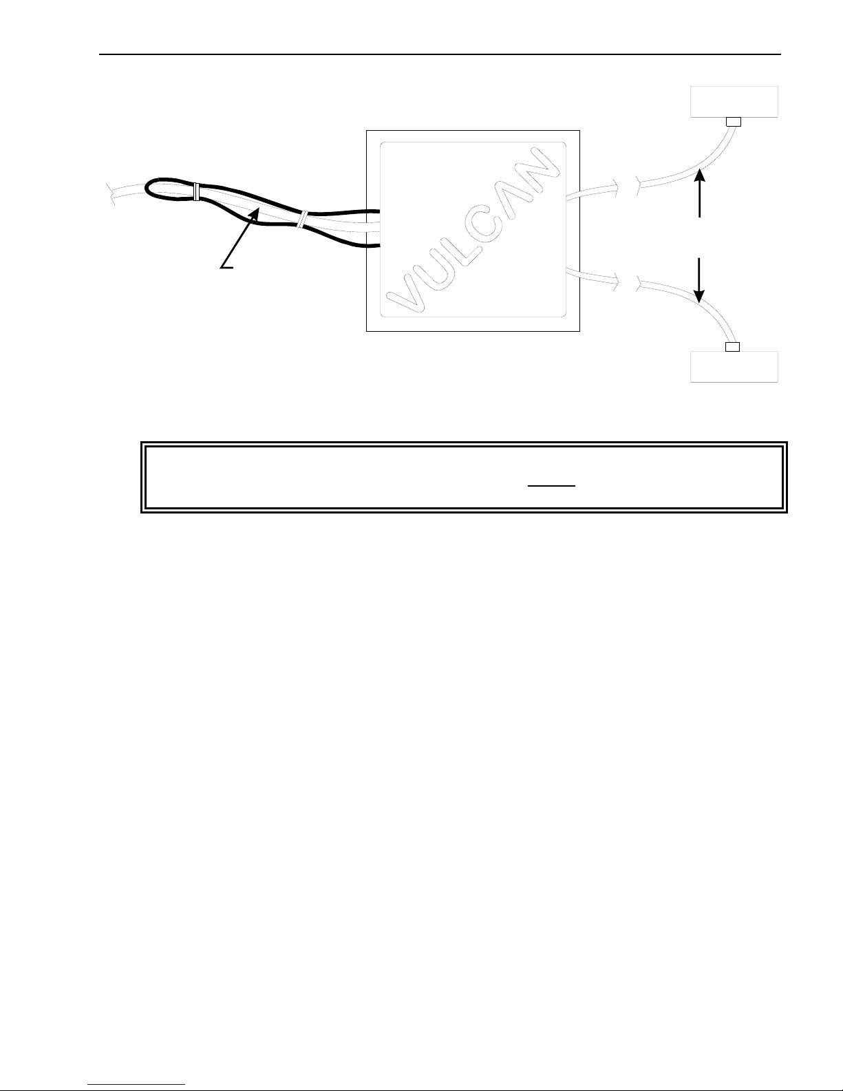
6. Connect the first VSL Vulcoder in the system to the 2-wire cable by splicing each color coded
wire from the communication cable and the VSL Vulcoder cable, (refer to Figure 1-J). When
using the Vulcan supplied 3M connector, do not strip the insulation from each wire. Be sure
to insert wires completely into the connector and check their position by looking through the
translucent connector body. Crimp the connector cap down flush with the top edge of the
connector body, ensuring a good connection. Tape the connection and all of the wires with the
orange insulation stripped off to help seal and prevent wire chaffing that can cause a wire to
short. Wire tie the splice so that the connection is strain relieved.
7. Find a suitable location for each additional VSL Vulcoder needed in the system. Connect
additional VSL Vulcoders in the system to the 2-wire cable by splicing each color coded wire
from the communication cable and the VSL Vulcoder cable (refer to Figure 1-J). When using
the Vulcan supplied 3M connector do not strip the insulation from each wire. Be sure to insert
wires completely into the connector and check their position by looking through the
translucent connector body. Then crimp the connector cap down flush with the top edge of the
connector body ensuring a good connection. Tape the connection and all of the wires with the
orange insulation stripped off to help seal and prevent wire chaffing that can cause a wire to
short. Wire tie the splice so that the connection is strain relieved.
June 21, 2006 VULCAN ON-BOARD SCALES 1-800-237-0022 Doc. 44-10032-001 Rev. C
© STRESS-TEK, INC. 2006

14 CHAPTER 1
Figure 1-J VSL Vulcoder Communication Connection
8. Once all of the Vulcoders have been installed, the Vulcoders must have either the wire loop cut
or uncut. Cutting the loop wire will designate the Vulcoder as a Front Vulcoder (refer to
Figure 1-K) and not cutting the Vulcoder designates the Vulcoder as a Rear Vulcoder (refer to
Figure 1-L). Following this procedure will enable the meter to properly assign channels.
For example, on a 2-channel system with the truck having a Front Vulcoder, and the trailer
having a Rear Vulcoder, the meter will sequence the Front Vulcoder as Channel A, and the
Rear Vulcoder as Channel B.
CUT
LOAD CELL
BLACK
CABLE
ORANGE
CABLE
LOAD CELL
Figure 1-K Front VSL Vulcoder Configuration
June 21, 2006 VULCAN ON-BOARD SCALES 1-800-237-0022 Doc. 44-10032-001 Rev. C
© STRESS-TEK, INC. 2006
CHAPTER 1 15
LOAD CELL
BLACK
CABLE
ORANGE
CABLE
LOAD CELL
Figure 1-L Rear VSL Vulcoder Configuration
WARNING: If installing the meter in a vehicle with a positive ground electrical system, the
meter chassis, mounting bracket, and mounting fasteners MUST be electrically isolated from
the vehicle chassis.
9. Find a suitable location for the meter and install the mounting bracket. Secure the VSL
Vulcoder cable so it does not obstruct other in cab equipment and strain relieve. Unplug the
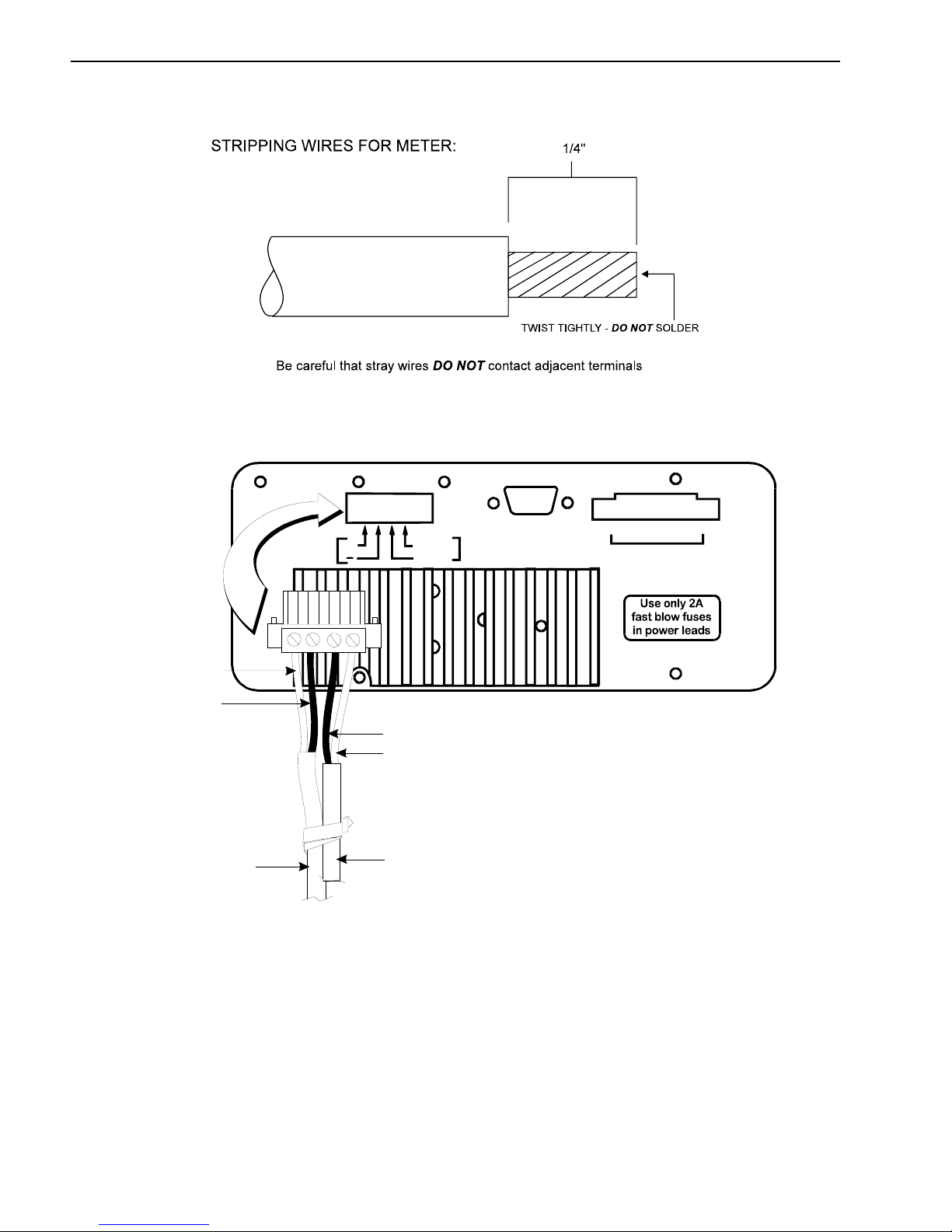
terminal block from the back of the meter, strip the wires, and connect the VSL Vulcoder wires
to the terminal block (refer to Figures 1-M and 1-N). Secure the power cable so it does not
obstruct other in cab equipment, strain relieve the power cable, and cut to length. Strip the
wires, and make all wire connections to the terminal block (refer to Figures 1-M and 1-N).
Note: Cut the shield wire off when stripping wires. Do not plug the terminal block into the
meter at this time.
10. Disassemble the positive fuse holder, (red wire). Apply grease to the positive connector at the
battery post to inhibit corrosion. Connect fused power leads directly to battery posts for best
operation. If not connecting directly to the battery, be sure to use a location that has the proper
voltage available at all times, and never more than 29 Vdc. Note: Vulcan V600 meters are
configured to be used in 12 Vdc system using 2 amp fast blow fuses in both power and
negative leads. To use the V600 meter in a 24 Vdc system, the 2 amp fast blow fuse must be
replaced with a 1 amp fast blow fuse in both power and negative leads. Refer to Section 7.2
“System Specifications.” Do not connect the power cable to a power source activated by the
key switch, power should be supplied at all times.
June 21, 2006 VULCAN ON-BOARD SCALES 1-800-237-0022 Doc. 44-10032-001 Rev. C
© STRESS-TEK, INC. 2006
16 CHAPTER 1
Figure 1-M: Stripping Wires for the Meter
Stress-Tek, Inc., Kent, WA, U.S.A
POWER
POWER
+
-
POWER
CABLE
12-24 Vdc
+
White
Green
GREEN
WHITE
VSL VULCODER
COMMUNICATION
(COMM LIN K)
RS-232
VSL
CABLE
1 2 3 4 5 6 7 8
Accessory Port
Figure 1-N: V600 Wire Connections to the Meter
11. Review steps 1 to 10 before connecting the terminal block to the back of the meter.
June 21, 2006 VULCAN ON-BOARD SCALES 1-800-237-0022 Doc. 44-10032-001 Rev. C
© STRESS-TEK, INC. 2006
CHAPTER 2 17
C H A P T E R 2 . 0
V600 METER OPERATION
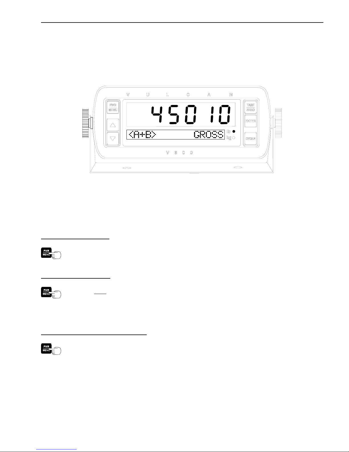
Figure 2-A: V600 Meter
2.1 POWER / MENU BUTTON OPERATION
2.1.1 POWERING THE METER ON / OFF
To Turn the Meter On:
Press the PWR / MENU button for less than 2 seconds.
To Turn the Meter Off:
Press and
2.1.2 ENTERING AND EXITING THE METER PROGRAM MENU
To Enter the Meter Program Menu:
After the meter has completed its start up routine and is running, press the PWR / MENU
button to enter the program menu.
hold the PWR / MENU button until the meter display goes blank.
June 21, 2006 VULCAN ON-BOARD SCALES 1-800-237-0022 Doc. 44-10032-001 Rev. C
© STRESS-TEK, INC. 2006
18 CHAPTER 2
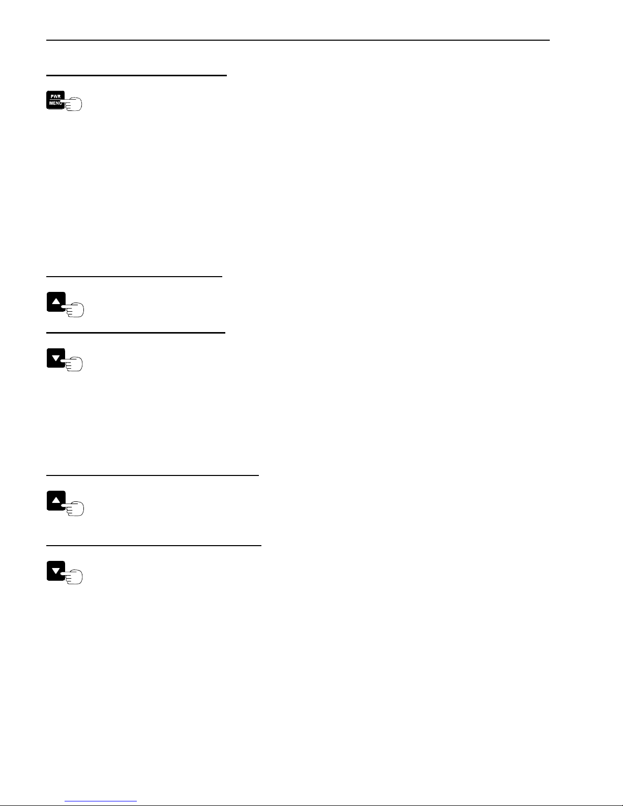
To Exit the Meter Program Menu:
Press the PWR / MENU button to exit from the program menu at any time to return to the
normal operating mode.
Note: If the PWR / MENU button is held too long the meter will display all 8’s and the meter will
turn off.
2.2 ARROW BUTTONS OPERATION
2.2.1 CHANGING DISPLAY INTENSITY
There are four levels of display intensity to choose from.
To Increase the Display Intensity:
Press the UP ARROW button, while in the normal operating mode.
To Decrease the Display Intensity:
Press the DOWN ARROW button, while in the normal operating mode.
2.2.2 INCREASE / DECREASE METER PROGRAM SETTINGS
The arrow buttons enable the user to customize the system to their particular needs. For example,
adjusting the system Tare Weights use the UP ARROW button to increase the weight.
To Increase A Particular Meter Feature:
Press the UP ARROW button to increase the displayed value.
To Decrease A Particular Meter Feature:
Press the DOWN ARROW button to decrease the displayed value.
June 21, 2006 VULCAN ON-BOARD SCALES 1-800-237-0022 Doc. 44-10032-001 Rev. C
© STRESS-TEK, INC. 2006
CHAPTER 2 19
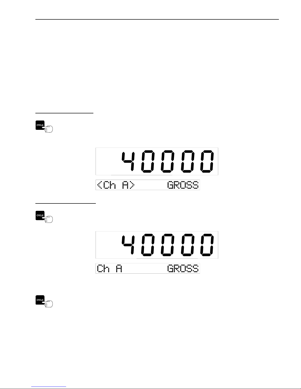
2.3 CYCLE BUTTON OPERATION
2.3.1 LOCKING THE METER ON A PARTICULAR CHANNEL
The lower yellow display indicates the channel, or group of channels, whose weight is being shown in
the large red upper display. The meter will automatically cycle through the channels and groups of
channels as determined by the display code setting.
If two or more letters are displayed, separated by a plus sign, this represents the sum of the weights on
those channels.
To Lock on a Channel:
When the desired channel or group of channels is being displayed, press the CYCLE button
to stop the automatic advance. The lock brackets “< >” are displayed when the meter is
locked on that particular channel(s).
To Unlock the Channel:
Press the CYCLE button again. The lock brackets “< >” are not displayed and the meter
will continue to cycle through the channels.
2.3.2 SCROLL THROUGH THE METER PROGRAM MENU FUNCTIONS
When in the Program Menu Mode, press the CYCLE button to scroll through the different
Program Menu items.
June 21, 2006 VULCAN ON-BOARD SCALES 1-800-237-0022 Doc. 44-10032-001 Rev. C
© STRESS-TEK, INC. 2006
20 CHAPTER 2
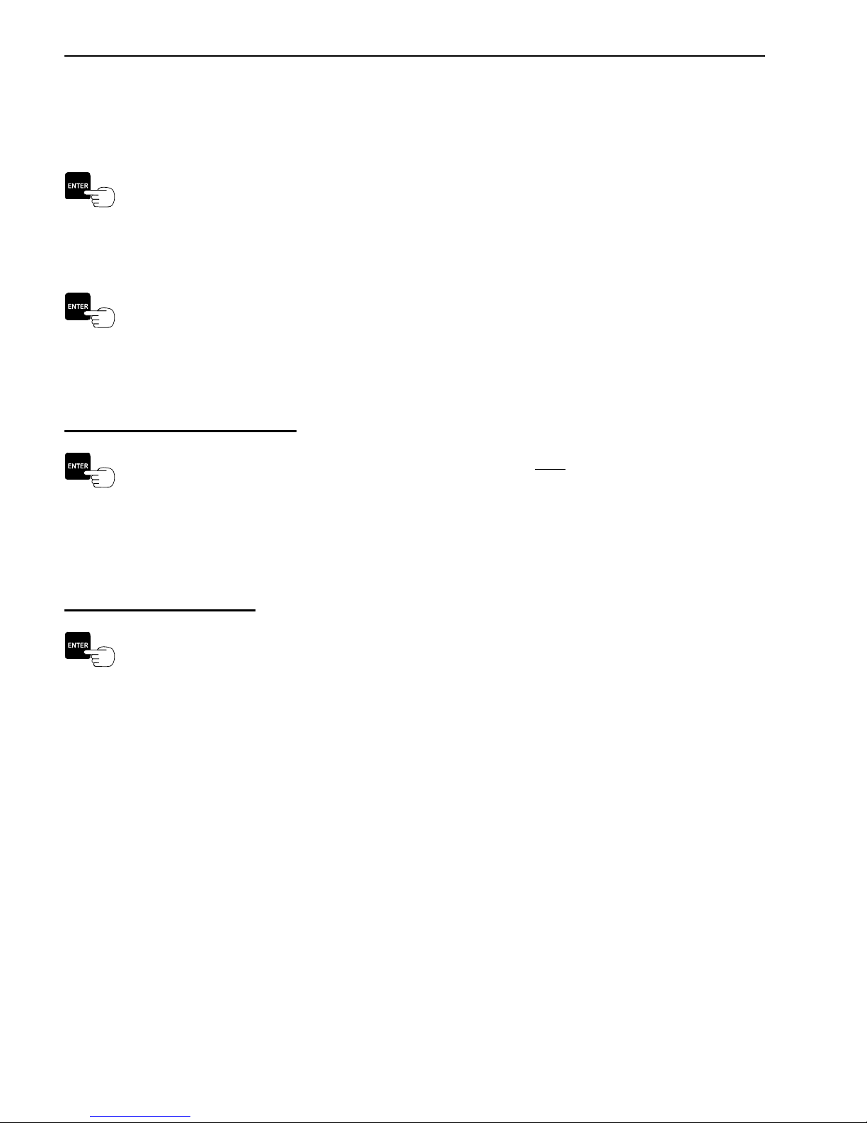
2.4 ENTER BUTTON OPERATION
2.4.1 SELECTS / ENTERS PROGRAM MENU ITEMS
Press the ENTER button to select the desired main program menu item when it is shown in
the lower display. For example, press the ENTER button to select the CONFIGURE
SYSTEM Menu after entering the Program Menu.
2.4.2 STORES NEWLY ADJUSTED METER SETTINGS
Press the ENTER button to store the newly adjusted settings. For example, after making
adjustments to the weight mode, press the ENTER button to store the desired setting and
return to the CONF: WT. MODE Menu option.
2.4.3 DISPLAYS TIME AND DATE
To Display The Time And Date:
While the meter is in the normal operating mode, press and hold the ENTER button until the
current time and date is displayed. The meter will continue to display the time until th e
ENTER button is pressed and held again. The meter will return to the normal weight
display.
2.4.4 PRINTS A WEIGHT TICKET
To Print A Weight Ticket:
While the meter is in the normal operating mode and the RS232 port is configured for a
printer, press the ENTER button to print a weight ticket.
June 21, 2006 VULCAN ON-BOARD SCALES 1-800-237-0022 Doc. 44-10032-001 Rev. C
© STRESS-TEK, INC. 2006
CHAPTER 2 21
2.5 TARE / ZERO BUTTON OPERATION
2.5.1 ZEROES METER VALUES
This feature is very useful when entering various numeric values. The meter will automatically zero
the displayed value when the TARE / ZERO button is pressed. For example, this can be used when
entering Tare Weights, Set Point values, AZT Range, etc.
To Adjust Meter input values to Zero:
Press the TARE / ZERO button to adjust the desired values to zero.
2.5.2 ZEROES METER DISPLAY IN THE "PICK-UP / DELIVERY MODE"
The Tare / Zero Button function enables the user to automatically zero the display for each channel,
at any time during normal operation. Refer to Section 3.2.1 to set the Weight Mode to Pick-up /
Delivery.
To Zero The Meter Display:
Press the TARE / ZERO button to zero the meter display during normal operation.
Note: The Tare / Zero button will only zero a channel or combination of channels when
locked on that particular channel or combination of channels.
2.5.3 DISPLAYS GROSS WEIGHT IN THE NET AND PICK-UP /
DELIVERY MODES
The Tare / Zero Button function enables the user to check the total gross weight while being in the Net
or Pick-up / Delivery Modes. The gross weight will be displayed on the smaller alpha-numeric
display. Note: If in the Pick-up / Delivery mode and locked on a channel or combination of channels,
this will also zero what is on the large display. If the meter is in the cycle mode, the gross weight will
be displayed without zeroing the upper display.
To Display The Total Gross Weight While In The Net or Pick-up / Delivery Modes:
Press and hold the TARE / ZERO button to display the total gross weight on the smaller
display without switching to the gross weight mode.
June 21, 2006 VULCAN ON-BOARD SCALES 1-800-237-0022 Doc. 44-10032-001 Rev. C
© STRESS-TEK, INC. 2006

22 CHAPTER 2
2.6 VULCODER UPDATING
After adjustments have been made to the meter’s set-up, tare or calibration values, the meter will
update the Vulcoders with the new information while displaying “WAIT . . .”. Note: Do not power
off the meter while it is updating the Vulcoders.
June 21, 2006 VULCAN ON-BOARD SCALES 1-800-237-0022 Doc. 44-10032-001 Rev. C
© STRESS-TEK, INC. 2006

CHAPTER 3 23
C H A P T E R 3 . 0
V600 - PROGRAM MENU (SYSTEM SETUP)
3.1 ENTERING THE PROGRAM MENU
The V600 meter program menu enables the user to:
• Configure System - Selects user configuration fields, allowing system flexibility and customizing
of the configuration items listed:, (Section 3.2)
• Weight Mode (Conf: Wt. Mode) - Configures the weight mode, either Gross, Net, or
Pickup/Delivery, (Section 3.2.1).
• Display Code (Conf: Disp Code) - Configures the program code, telling the meter what
channels and combination of channels to display, (Section 3.2.2).
• Set Point (Conf: Set Points) - Configures the set points, (Section 3.2.3)
• Cycle Time (Conf: Cycle Time) - Configures the channel cycle time, (Section 3.2.4).
• RS 232 Port (Conf: RS232 Port) - Configures the data format of the RS 232
communications port, (Section 3.2.5).
• Print Headers (Conf: Print Hdrs) - Configures customized print headings used when
printing weight tickets, (Section 3.2.6).
• Date (Conf: Date) - Configures the current date, (Section 3.2.7).
• Time (Conf: Time) - Configures the current time, (Section 3.2.8).
• Scale ID (Conf: Scale ID) - Configures the scale or truck ID associated with currently
used V600 system, (Section 3.2.9).
• Lock (Conf: Lock) - Configures the Setup / Calibration Lock. The lock must be in the Off
position to adjust the Tare or Calibration settings for the scale. Turning the lock to the On
position will prevent changes to the system’s calibration, (Section 3.2.10).
• Setup / Calibration - Selects the system setup and calibration (Section 3.3), items listed:,
(Section 3.3)
• Tare Weight (Set: Tare Weight) - Sets the desired tare weight (Empty Weight) of each
active channel, (Section 3.3.1).
• Cal Number (Set: Cal Number) - Sets the calibration number for each active channel,
(Section 3.3.2).
• Full Weight (Set: Full Weight) - Sets the projected full, calibrated weight for each active
channel, (Section 3.3.3).
• Post Cal (Set: Post Cal) - Sets the system calibration after the load is emptied for each
active channel, (Section 3.3.4).
• Grad Size (Set: Grad Size) - Sets the graduation for displaying weight, (Section 3.3.5).
• Units (Set: Units) - Sets the units of measure, either pounds or kilograms, (Section 3.3.6).
• Auto Zero Tracking (Set: AZT Range) - Sets the auto zero tracking range for each active
channel, (Section 3.3.7)
June 21, 2006 VULCAN ON-BOARD SCALES 1-800-237-0022 Doc. 44-10032-001 Rev. C
© STRESS-TEK, INC. 2006
24 CHAPTER 3
• Sample Size (Set: Sample Size) - Sets the number of weight readings averaged before
displaying a weight, i.e. the higher the number, the more the readings are filtered. The
higher filtering is needed when there is movement during the weighing process, (Section
3.3.8).
• Sequence Chanls - Assigns the proper sequence to the Vulcoders in the system, (Section 3.4).
• System Test Menu - Selects the diagnostic system test, (Section 3.5).
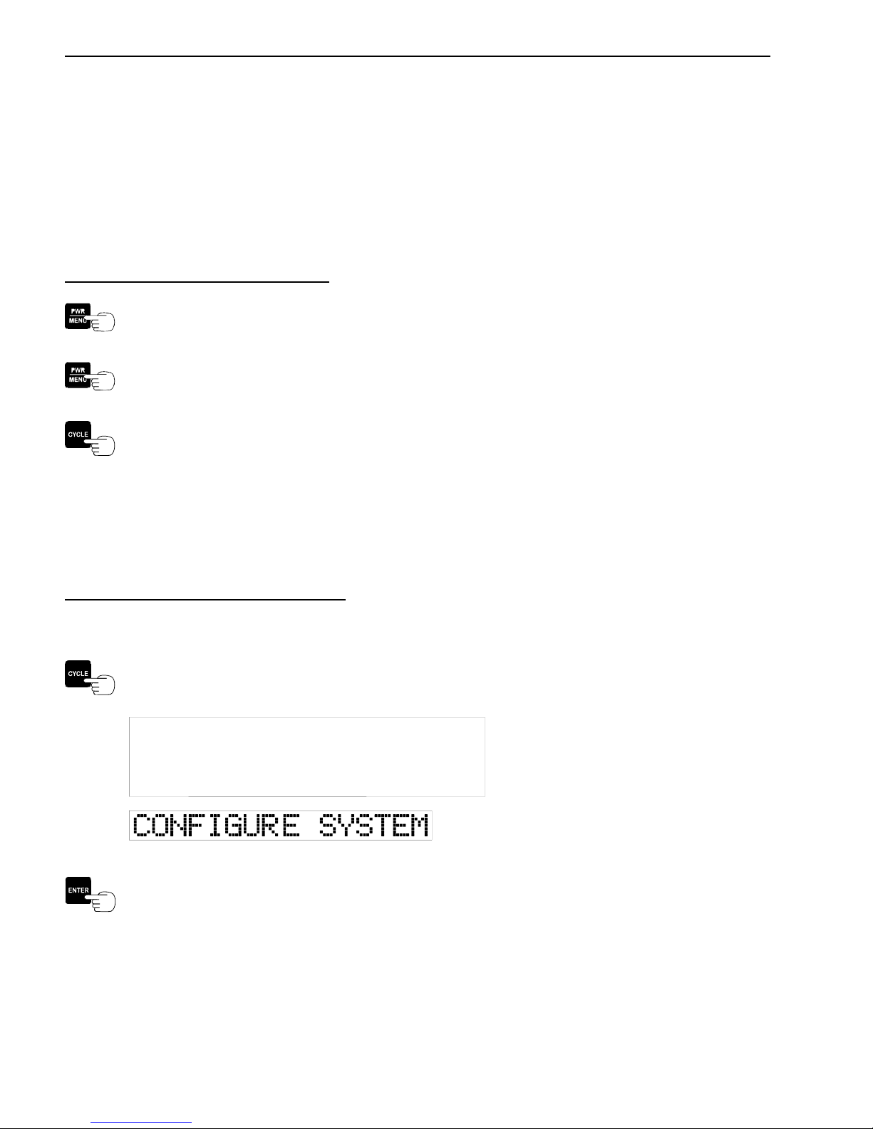
To Enter the Meter Program Menu:
Press the PWR / MENU button to turn on the meter.
After the meter has completed its start up routine and is running, press the PWR / MENU
button to enter the program menu.
Press the CYCLE button to go through the four different main program items: Configure
System, Setup / Calibration, Sequence Chanls, and System Test.
Note: If the PWR / MENU button is held too long, the meter display will display all 8’s and the meter
will turn off.
3.2 ENTERING THE CONFIGURE SYSTEM MENU
To Enter the Configure System Menu:
Enter the Program Menu (Section 3.1)
Press the CYCLE button until CONFIGURE SYSTEM is displayed.
Press the ENTER button to select the CONFIGURE SYSTEM Menu.
June 21, 2006 VULCAN ON-BOARD SCALES 1-800-237-0022 Doc. 44-10032-001 Rev. C
© STRESS-TEK, INC. 2006
CHAPTER 3 25
3.2.1 CONFIGURE THE WEIGHT MODE (GROSS, NET, OR PICK-UP)
The Vulcan Scale System can be used to measure weight by three different methods. These methods
are Gross Vehicle Weight, Net Payload Weight, or Individual Pick-up Weight.
Gross Vehicle Weight
Entire truck weight including fuel, equipment, personnel, and payload.
In order to use the Gross Vehicle Weight method, the Tare Weight for each channel must be entered.
The Tare Weight is the weight of the empty truck with fuel, equipment, personnel, and no payload.
For example, if the Tare Weight is 30,000 lb the meter will display this weight before any payload has
been loaded. As the payload increases, the weight displayed on the meter will also increase. For a
2-channel system (A and B), the total Gross Vehicle Weight is displayed on Channel (A+B). For a
4-channel system, the total Gross Vehicle Weight is displayed on Channel (A+B+C+D).
Net Payload Weight
Weight of the truck’s payload only.
By using the Net Payload Weight method, payload pickups are measured cumulatively. Net Payload
Weight can be measured for each channel the weight displayed at all times is the Net Payload Weight.
Note: To temporarily display the total gross weight, refer to section 2.5.3.
Individual Pick-up and Delivery Weight
This method is used for weighing individual customer pick-ups or deliveries during a route.
Note: To temporarily display the total gross weight, refer to section 2.5.3.
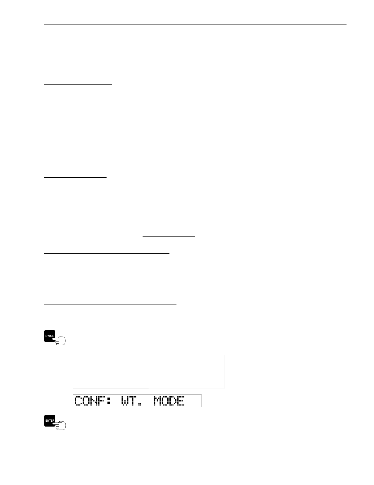
Procedure to Configure the Weight Mode:
Enter the CONFIGURE SYSTEM Menu, (Section 3.2)
Press the CYCLE button until CONF: WT. MODE is displayed.
Press the ENTER button to select the CONF: WT. MODE Option.
June 21, 2006 VULCAN ON-BOARD SCALES 1-800-237-0022 Doc. 44-10032-001 Rev. C
© STRESS-TEK, INC. 2006
26 CHAPTER 3
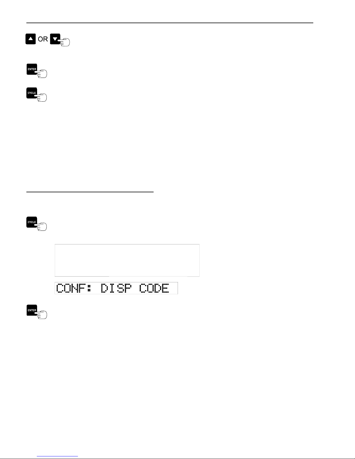
Press the UP or DOWN ARROW buttons until the desired weight mode appears.
There are three weight modes to choose from: [GROSS], [NET], or [P/D], where
[P/D] refers to Individual Pick-up and Delivery mode.
Press the ENTER button to store the weight mode and return to the CONF: WT. MODE
Menu option.
Press the CYCLE button to advance to the next CONFIGURE SYSTEM Menu option.
3.2.2 CONFIGURE THE DISPLAY CODE
The number of VSL Vulcoders connected to the Vulcan system corresponds to the number of
channels. The first number in the display code is the number of channels. The next two numbers or
letters determine how the channels will be displayed. When code 000 is selected, the meter
automatically selects the display code depending on how many VSL Vulcoders are communicating
with the meter at power up. The meter display code allows the user to display a combination of one or
more of the available channels. Refer to the list of display codes listed below.
Procedure to Configure The Display Code:
Enter the Configure System Menu, (Section 3.2)
Press the CYCLE button until CONF: DISP CODE is displayed.
Press the ENTER button to select the CONF: DISP CODE option.
June 21, 2006 VULCAN ON-BOARD SCALES 1-800-237-0022 Doc. 44-10032-001 Rev. C
© STRESS-TEK, INC. 2006
CHAPTER 3 27
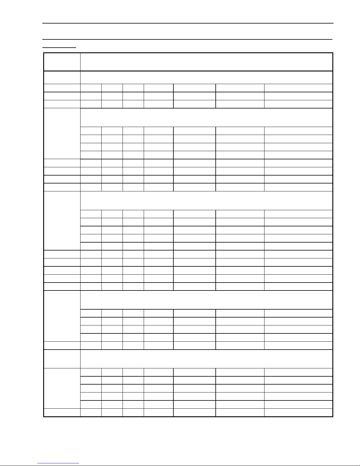
Table of Display Codes (The first number in the display code refers to the number of channels in
the system):
Display Code
000 Automatically selects codes 101, or 201, or 301, or 402, or 501, or 601, depending on the number of VSL Vulcoders
101 A
201 A B A+B
202 A B
300 Consists of the following special grouping codes (3c1, 3c2, 3c3, 3c4) that can be quickly selected using the Cycle key
without going into the Program Menu. In normal operation, press and hold the Cycle key down, then use the Up or
Down arrow keys to select the group desired.
3c1 A B A+B
3c2 B C B+C
3c3 A+B+C
3c4 A B C A+B+C
301 A B C A+B+C
302 A B A+B C A+B+C
303 A B C B+C A+B+C
304 A B C
400 Consists of the following special grouping codes (4c1, 4c2, 4c3, 4c4, 4c5) that can be quickly selected using the
Cycle key without going into the Program Menu. In normal operation, press and hold the Cycle key down, then use
the Up or Down arrow keys to select the group desired.
4c1 A B A+B
4c2 B C B+C
4c3 C D C+D
4c4 A+B+C+D
4c5 A B A+B C D C+D A+B+C+D
401 A B C D A+B+C+D
402 A B A+B C D C+D A+B+C+D
403 A B C B+C D A+D A+B+C+D
404 A B A+B C D C+D
405 A B D A+B+D
500 Consists of the following special grouping codes (5c1, 5c2, 5c3, 5c4) that can be quickly selected using the Cycle key
without going into the Program Menu. In normal operation, press and hold the Cycle key down, then use the Up or
Down Arrow keys to select the group desired.
5c1 A B A+B
5c2 B C B+C
5c3 C D C+D
5c4 D E D+E
501 A B C D E A+B+C+D+E
600 Consists of the following special grouping codes (6c1, 6c2, 6c3, 6c4, 6c5) that can be quickly selected using the
Cycle key without going into the Program Menu. In normal operation, press and hold the Cycle key down, then use
the Up or Down Arrow keys to select the group desired.
6c1 A B A+B
6c2 B C B+C
6c3 C D C+D
6c4 D E D+E
6c5 E F E+F
601 A B C D E F A+B+C+D+E+F
Displayed Channels
communicating with the meter.
Figure 3-A: Display Codes - V600 Meter
June 21, 2006 VULCAN ON-BOARD SCALES 1-800-237-0022 Doc. 44-10032-001 Rev. C
© STRESS-TEK, INC. 2006
28 CHAPTER 3
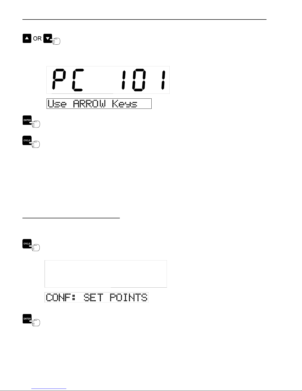
Press either the UP or DOWN ARROW buttons to select the desired channel
display code.
Example:
Press the ENTER button to store the display code information and return to the CONF:
DISP CODE Menu option.
Press the CYCLE button to advance to the next CONFIGURE SYSTEM Menu option.
3.2.3 CONFIGURE THE SET POINTS
Set points enable the meter to communicate with the user when a particular weight is reached on a
particular channel or combination of channels. There are two individual set points with capabilities of
driving a relay for each set point configuration. When each set point is activated, the meter display
will show that the set point weight has been reached and if a relay is connected, the meter will activate
the relay which can be connected to a light, horn or any other device used to alert the user.
Procedure to Configure The Set Point:
Enter the CONFIGURE SYSTEM Menu, (Section 3.2).
Press the CYCLE button until CONF: SET POINT is displayed.
Press the ENTER button to select the CONF: SET POINT option.
June 21, 2006 VULCAN ON-BOARD SCALES 1-800-237-0022 Doc. 44-10032-001 Rev. C
© STRESS-TEK, INC. 2006

CHAPTER 3 29
Configure Set Point - Selects user set point configuration fields, allowing flexibility and customizing
of the set point configuration items listed:
• Configuration of Relay 1 (Conf: RELAY 1) - Configures the set point to activate relay 1,
(Section 3.2.3A).
• Configuration of Relay 2 (Conf: RELAY 2) - Configures the set point to activate relay 2,
(Section 3.2.3B).
• Configuration of Delta Weight (Conf: DELTA WT.) - Configures the set point Delta
Weight, (Section 3.2.3C).
• Configuration of On Time (Conf: ON TIME) - Configures the set point activation On
Time, (Section 3.2.3D).
3.2.3A CONFIGURE RELAY 1
Relay 1 is one out of two relays in the Set Point operation. Each relay can be configured to monitor
one of the following channels or combination of channels, (refer to Figure 3-B) independent of the
other relay:
RELAY CHANNEL
CONFIGURATION SELECTIONS
[OFF] Meter Relay Set Points are turned off.
[LOCKED ONLY] Meter must be "Locked" (See 2.3.1) on a channel of
[CH A ONLY] Channel A will activate the relay.
[CH B ONLY] Channel B will activate the relay.
[CH C ONLY] Channel C will activate the relay.
[CH D ONLY] Channel D will activate the relay.
[CH E ONLY] Channel E will activate the relay.
[CH F ONLY] Channel F will activate the relay.
[A+B] The total of A and B will activate the relay.
[B+C] The total of B and C will activate the relay.
[C+D] The total of C and D will activate the relay.
[D+E] The total of D and E will activate the relay.
[E+F] The total of E and F will activate the relay.
[A+B+C] The total of A, B and C will activate the relay.
[D+E+F] The total of D, E and F will activate the relay.
[A+B+C+D] The total of A, B, C, and D will activate the relay.
[A+B+C+D+E] The total of A, B, C, D, and E will activate the relay.
[A+B+C+D+E+F] The total of A, B, C, D, E, and F will activate the relay.
Figure 3-B: V600 Meter Relay Channel Configuration Selections.
DESCRIPTION
group of channels to activate the relay.
June 21, 2006 VULCAN ON-BOARD SCALES 1-800-237-0022 Doc. 44-10032-001 Rev. C
© STRESS-TEK, INC. 2006
30 CHAPTER 3
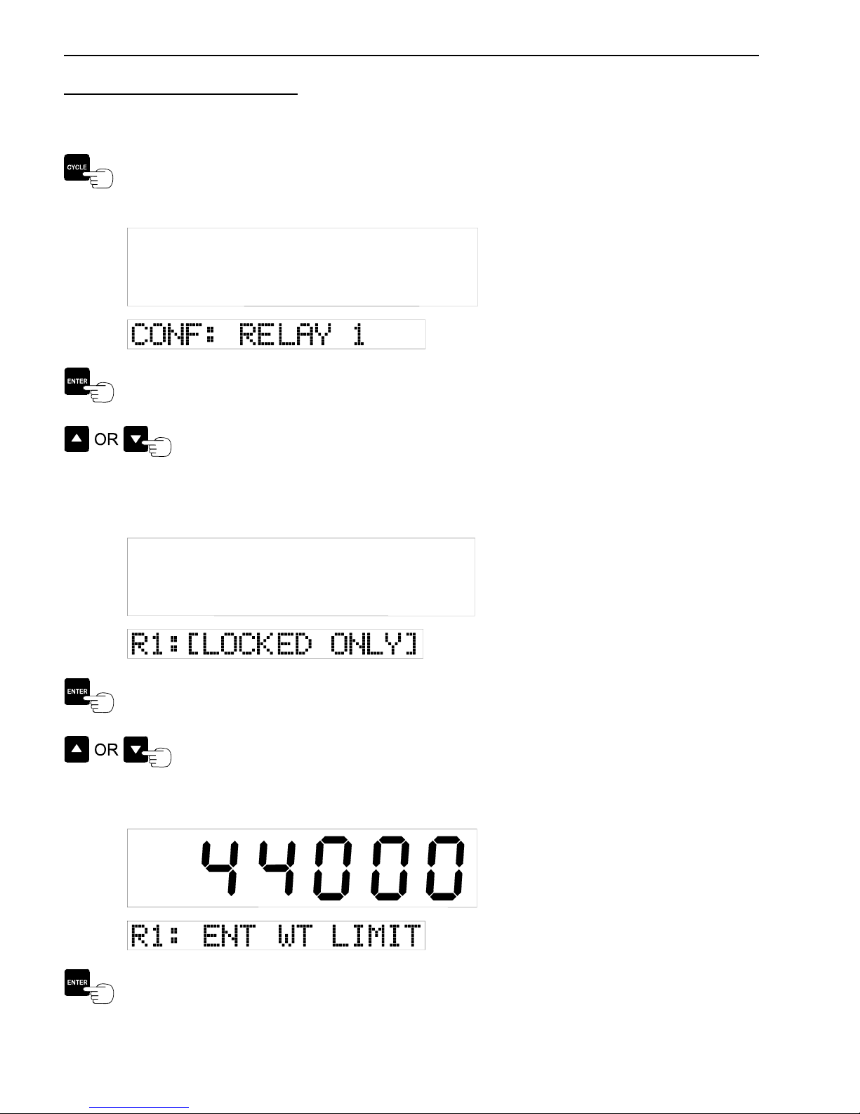
Procedure to Configure Relay 1:
Enter the CONF: SET POINT Menu, (Section 3.2.3)
Press the CYCLE button until CONF: RELAY 1 is displayed.
Press the ENTER button to select the CONF: RELAY 1 option.
Press either the UP or DOWN ARROW buttons to select the desired channel or
combination of channels, which will activate Relay 1. Refer to Figure 3-B, for the
list of channel combinations.
Example:
Press the ENTER button to store the selected channel or channel combination used for
activating Set Point Relay 1 and advance to setting the Set Point Weight.
Press either the UP or DOWN ARROW buttons to adjust the weight limit which
activates relay 1.
Example:
Press the ENTER button to store the desired weight limit and return to the CONF: RELAY
1 Menu option.
June 21, 2006 VULCAN ON-BOARD SCALES 1-800-237-0022 Doc. 44-10032-001 Rev. C
© STRESS-TEK, INC. 2006
 Loading...