

Page 1
217-8080
Talon SRX - User’s Guide
crosstheroadelectronics.com vexpro.com
Copyright 2017, Cross The Road Electronics, VEX Robotics Inc.
Updated: 2017-02-03
1
Talon SRX – User’s Guide
Cross The Road Electronics
www.crosstheroadelectronics.com
Page 2
217-8080
Talon SRX - User’s Guide
crosstheroadelectronics.com vexpro.com
Copyright 2017, Cross The Road Electronics, VEX Robotics Inc.
Updated: 2017-02-03
2
Table of Contents
The Talon SRX at a Glance: ................................................................................................................. 4
Electrical/Mechanical Specs: ................................................................................................................ 5
1. Installing a Talon SRX ...................................................................................................................... 7
1.1. Wiring the Motor Output .............................................................................................................. 7
1.2. Wiring the Power Input ............................................................................................................... 7
1.3. Wiring the Talon SRX Signal Input ............................................................................................. 8
1.3.1. Configuring a Talon SRX with CAN bus on a roboRIO ........................................................ 8
1.3.2. Wiring the Talon SRX for use with CAN bus ...................................................................... 10
1.3.3. Wiring Talon SRX for PWM Control ................................................................................... 12
1.3.4. Firmware requirements (PWM and CAN bus) .................................................................... 14
1.4. Wiring Sensors to the Talon SRX ............................................................................................. 17
1.4.1. Data Port Pinout................................................................................................................. 17
1.4.2. Analog Input ....................................................................................................................... 18
1.4.3. Quadrature Encoder Input ................................................................................................. 19
1.4.4. Forward & Reverse Limit Switch Inputs ............................................................................. 20
1.4.5. Connecting to the Data Port ............................................................................................... 22
1.4.6. Encoder (and Limit Switch) Breakout ................................................................................. 23
1.4.7. Analog 5V Encoder (and Limit Switch) Breakout ............................................................... 25
1.4.8. Heat Shrink Use with Breakout .......................................................................................... 26
1.5. Mounting the Talon SRX ........................................................................................................... 27
1.6. General Robot Wiring Guidelines ............................................................................................. 27
1.7. Applying Power for the First Time ............................................................................................. 28
2. Additional Information ..................................................................................................................... 29
2.1. Brake & Coast Modes ............................................................................................................... 29
2.1.1. Switching Between Brake & Coast Using the B/C CAL Button: ......................................... 29
2.1.2. Switching Between Brake & Coast Using CAN bus: .......................................................... 29
2.1.3. Switching Between Brake & Coast Using CAN Control Frames ........................................ 29
2.2. PWM Calibration ....................................................................................................................... 30
2.2.1. To Calibrate the Talon SRX: .............................................................................................. 30
Page 3
217-8080
Talon SRX - User’s Guide
crosstheroadelectronics.com vexpro.com
Copyright 2017, Cross The Road Electronics, VEX Robotics Inc.
Updated: 2017-02-03
3
2.2.2. To Restore Default Calibration: .......................................................................................... 31
2.3. Blink Codes............................................................................................................................... 32
2.3.1. Blink Codes – Damaged Hardware .................................................................................... 33
2.4. Performance Data ..................................................................................................................... 34
2.5. Frequently Asked Questions: .................................................................................................... 35
3. Troubleshooting .............................................................................................................................. 39
4. Compliance ..................................................................................................................................... 43
5. Revision History: ............................................................................................................................. 44
Page 4
217-8080
Talon SRX - User’s Guide
crosstheroadelectronics.com vexpro.com
Copyright 2017, Cross The Road Electronics, VEX Robotics Inc.
Updated: 2017-02-03
4
Talon SRX – User’s Guide
The Talon SRX is a speed controller designed through collaboration between VEX Robotics
(VEX.com) & Cross the Road Electronics (crosstheroadelectronics.com) that allows fine control and
high performance of brushed DC motors in competition robotics applications. The Talon SRX handles
high current loads with minimal voltage drop and heat generation. Its linear output and Brake/Coast
options allow for precise motor control, making it well suited for everything from drivetrains to shooter
wheels.
The Talon SRX’s Data Port and CAN bus features make it the most capable motor controller
available for competition robotics. The Data Port allows Quadrature Encoders, Limit Switches and
Analog Sensors to be connected directly to the motor controller. Sensors that are connected through
the Data Port are directly processed by the Talon SRX, freeing up resources in the primary robot
controller for more complex user code. When using CAN bus, up to 63 Talon SRXs can communicate
with the primary robot controller for tasks like field-upgrade, Data Port Configuration, dynamic
Brake/Coast toggling, and motor control.
The lightweight aluminum case was designed using extensive Finite Element Heat Transfer Analysis
(FEHTA). The result is a fully sealed design that makes fans optional. This, combined with a 3.25 sq.
in footprint, a variety of built-in mounting options, and super-flexible/high-strand-count leads, makes
installation a breeze.
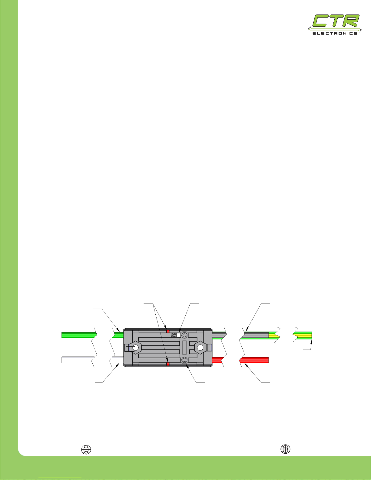
The Talon SRX at a Glance:
(M-)
Signal
Wires
Data Port
Positive
Output
(M+)
Positive Input
(V+)
Signal
Wires
Output GND
(M-)
Status
LEDs
B/C Cal
Button
Input GND
(V-)
Page 5
217-8080
Talon SRX - User’s Guide
crosstheroadelectronics.com vexpro.com
Copyright 2017, Cross The Road Electronics, VEX Robotics Inc.
Updated: 2017-02-03
5
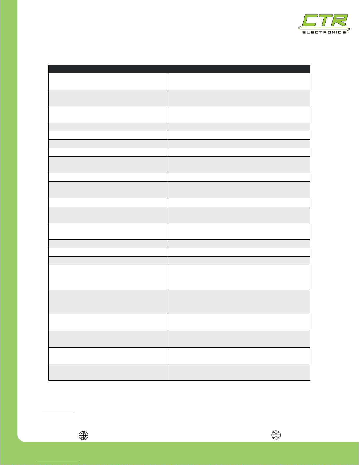
Electrical/Mechanical Specs:
Talon SRX Specs
Outside Dimensions
2.75” x 1.185” x 0.96”
[69.9mm x 30.2mm x 24.4mm]
Weight
0.23 lbf [0.10 kgf] (excluding wiring)
Supported Communication
Protocols
PWM, DWCAN bus (1Mbps)
Nominal Voltage
12V
Min/Max Voltage
6 – 28V
Continuous Current
60A
Surge Current (2 sec)
100A
PWM Input Pulse
(High Time)
1 – 2 ms Nominal
0.6 – 2.4ms max
PWM Input Rate (Period)
2.9 – 100ms
PWM Output Chop Rate
(Switching Frequency)
15.625 kHz
Minimum Throttle (Dead band)
4%
PWM Logic High
Min Voltage Threshold
1V
PWM Logic Low
Max Voltage Threshold
0.4V
PWM Input Min Current
< 1mA
Max Quadrature CPR
(1)
80,000,000 / Peak RPM
Max Quadrature RPM
(1)
80,000,000 / CPR
Logic High
Min Input Voltage
Quad A/B/Idx/Limit Fwd/Rev
2.64V
Logic Low
Max Input Voltage
Quad A/B/Idx/Limit Fwd/Rev
0.66V
Min/Max Voltage
Analog Input
0 – 3.3V
Min/Max Voltage
Quad A/Limit Fwd/Rev
0 – 5V
Min/Max Voltage
Quad B and Quad Idx
0 – 3.3V
(2)
(Talon revision 1.5 and earlier)
0 – 5V (Talon revision 1.6 and on)
Data Port Max Current
3.3V (pin1) : 33mA
5V (pin2) : 50mA
Note 1: This is based on the maximum quadrature edge-to-edge rating of 187.5ns.
Note 2: A late errata on the microcontroller was released after Talon SRX 2015 season production, indicating the Quad B and Quad Idx are
not 5V tolerant. As a result, Talons with revision 1.5 (and earlier) should not use sensor cable/breakouts that allow >3.6V on Quad B or Quad
Idx, as this may damage Talon SRX. See Talon SRX Software Reference Manual (Section 2) for how to detect Hardware Revision. See
Section 1.4.6.1 for the updated breakout solution.
Page 6
217-8080
Talon SRX - User’s Guide
crosstheroadelectronics.com vexpro.com
Copyright 2017, Cross The Road Electronics, VEX Robotics Inc.
Updated: 2017-02-03
6
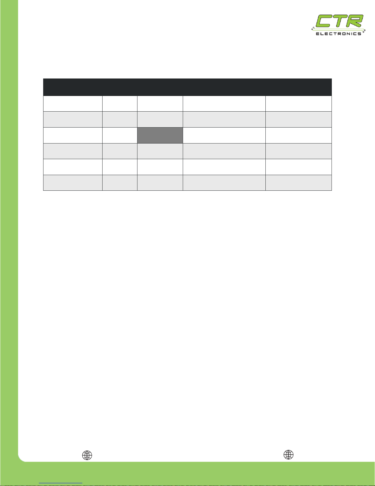
The power inputs and outputs of the Talon SRX are indicated by markings on the housing.
They are also shown in the table below:
Wire
Case
Marking
Wire Color
Wire Gauge
Wire Length
± 0.25in [6.35mm]
Positive Input
V+
Red
12 AWG
(600 strand min)
5.5in [139.7mm]
Input Ground
GND
Black
12 AWG
(600 strand min)
5.5in [139.7mm]
Positive Output
M+
White
12 AWG
(600 strand min)
5.5in [139.7mm]
Output Ground
M-
Green
12 AWG
(600 strand min)
5.5in [139.7mm]
CAN-High/
PWM Signal
None
Yellow
22 AWG
11.0in [279.4mm]
CAN-Low/
PWM Ground
None
Green
22 AWG
11.0in [279.4mm]
Note: There are (2X) yellow and (2X) green 22AWG signal wires on each Talon SRX. Signal wires of
the same color are electrically identical.
Page 7
217-8080
Talon SRX - User’s Guide
crosstheroadelectronics.com vexpro.com
Copyright 2017, Cross The Road Electronics, VEX Robotics Inc.
Updated: 2017-02-03
7
1. Installing a Talon SRX
Wiring a speed controller has never been easier than with the Talon SRX. By following a few quick
steps, your robot will be up and running in no time.
1.1. Wiring the Motor Output
Connect the white wire to the M+ side of the motor and the green wire to the M- side of the motor
using tightly crimped connectors.
If the motor’s inputs are not marked, the polarity of the input may be chosen by the user. Be sure to
connect the output wires to motors with consistent polarity so each motor will rotate the same
direction when given the same PWM signal. Reversing the output wire connections will result in the
motor rotating the opposite direction when given the same PWM signal.
In many cases, the output leads of the Talon SRX will not be long enough to reach the motor it is
controlling, so an extension cable will be required. Extension cables should be made using
appropriately sized wire and connected using tightly crimped connectors.
Note: For the most robust connection, it is highly recommended that all connectors are crimped and
soldered.
1.2. Wiring the Power Input
WARNING: TO MAXIMIZE PERFORMANCE, THE TALON SRX DOES NOT INCLUDE
REVERSE POLARITY PROTECTION. IF POWER IS APPLIED BACKWARDS, THE
TALON SRX MAY BE PERMANENTLY DAMAGED.
To power the Talon SRX, connect the positive input (red) wire to the selected positive terminal of the
Power Distribution Panel (PDP), and the input ground (black) wire to the corresponding ground
terminal. In many cases, the Talon SRX may be wired directly to the robot’s PDP without extension
cables – this is preferable since it reduces the number of electrical connections. If the robot’s design
does not allow for a direct connection to the PDP, extension cables may be used.
Always keep good electrical practices in mind when designing a robot's electrical system. The Talon
SRX’s source voltage should never exceed 28V. In addition, a 40A or smaller breaker should be
used in series with the Talon SRX’s positive input.
Page 8
217-8080
Talon SRX - User’s Guide
crosstheroadelectronics.com vexpro.com
Copyright 2017, Cross The Road Electronics, VEX Robotics Inc.
Updated: 2017-02-03
8
1.3. Wiring the Talon SRX Signal Input
The Talon SRX is capable of being controlled using either CAN bus or a PWM signal. Each input type
has its own pros and cons that should be carefully considered before wiring and programming.
The CAN bus capability of the Talon SRX is one of its most powerful features. It allows up to 63 Talon
SRXs to be daisy chained – this means Talon SRXs can plug into each other and only require a
single output on the primary robot controller. CAN bus also allows two-way communication between
the Talon SRX and the robot controller, which enables tasks like field-upgrade, Data Port
configuration, dynamic Brake/Coast toggling, and motor control. When using CAN bus, sensors that
are connected to the Data Port are monitored by the Talon SRX meaning that the primary robot
controller has more processing power to devote to other tasks.
One of the simplest ways to control a Talon SRX is using a Pulse Width Modulation (PWM) signal.
Unlike CAN bus control, using PWM requires that each Talon SRX must be individually connected to
a different output on the system’s primary robot controller – Talon SRXs cannot be daisy chained in
PWM mode. When using PWM to control the Talon SRX, only limit switches (or equivalent binary
switches) may be used with the Data Port. Encoders or Analog sensors cannot be used.
1.3.1. Configuring a Talon SRX with CAN bus on a roboRIO
Talon SRX automatically detects CAN bus traffic so there is no need to select “CAN” vs “PWM”. The
only configuration that is necessary is assigning Device IDs to prevent common-ID Talons (more than
one Talon with the same device ID). This is a common problem condition that prevents reliable
communication between the primary robot controller and other CAN devices.
However the roboRIO Web-based Configuration page is tolerant of common-ID Talons to a degree
(up to typically five or less common-ID Talons), so you can discover, firmware update, modify settings,
and change the device ID of a common-ID Talon to an unused device ID. More information can be
found in the Software Reference Manual.
Page 9
217-8080
Talon SRX - User’s Guide
crosstheroadelectronics.com vexpro.com
Copyright 2017, Cross The Road Electronics, VEX Robotics Inc.
Updated: 2017-02-03
9
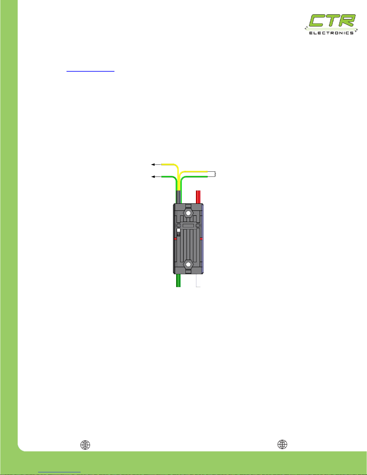
Another option is to explicitly ensure each Talon SRX has a unique ID assigned to it prior to wiring the
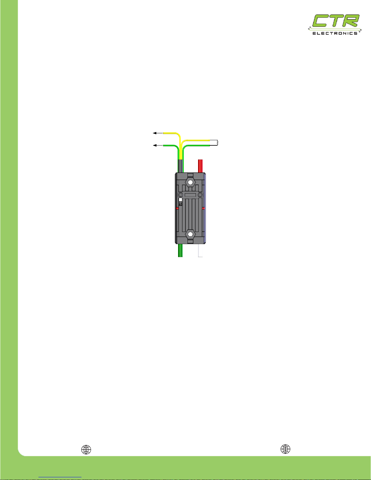
entire CAN bus harness. To do this, connect a yellow signal wire to the NI roboRIO CAN terminal
marked “H” and connect a green signal wire to the NI roboRIO CAN terminal marked “L” as shown in
the figure below. Connect the remaining green and yellow signal wires using a 120 Ω resistor as
shown in the figure below. Alternatively the Power Distribution Panel’s CAN interface can be wired
instead of a 120 Ω resistor since the PDP has an integrated resistor.
After the Talon SRX has been connected to the roboRIO, ensure there are no shorts, then apply
power and use the roboRIO Web-based Configuration page to assign the Talon SRX a unique ID.
TIP: Avoid using the default ID “0”, this makes adding new default Talons easier. The unique
ID is a 6-bit number; valid numbers are from 1 to 62. After the unique ID has been assigned, remove
power and repeat the process for each Talon SRX.
WARNING: When applying power to the Talon SRX for programming its unique ID, it may be
tempting to connect it directly to a 12V robot battery without a breaker – this is NOT recommended. If
the temporary power connectors short without a breaker protecting the wires, there is a high risk of an
electrical fire.
To CAN “L” Terminal
120 Ω
Resistor
or PDP
To CAN “H” Terminal
Page 10
217-8080
Talon SRX - User’s Guide
crosstheroadelectronics.com vexpro.com
Copyright 2017, Cross The Road Electronics, VEX Robotics Inc.
Updated: 2017-02-03
10
1.3.2. Wiring the Talon SRX for use with CAN bus
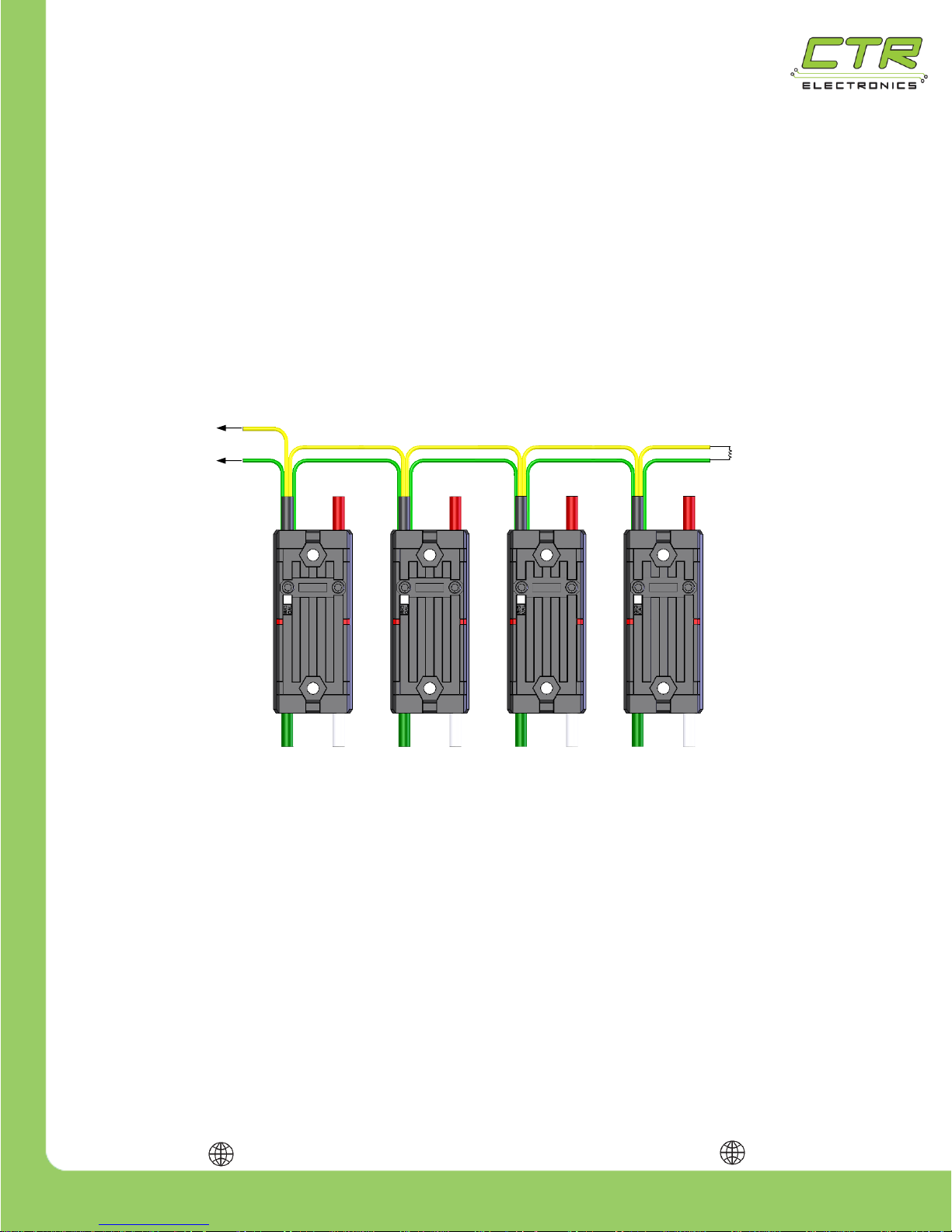
To wire CAN bus, connect a yellow signal wire to the CAN terminal marked “H” on the NI roboRIO
and connect a green signal wire to the CAN terminal marked “L” on the NI roboRIO.
To connect additional Talon SRXs, use tightly crimped connectors to connect the signal wires greento-green & yellow-to-yellow as shown below. For the best connection, it is highly recommended that
each connector is crimped and soldered. The yellow and green wires should also be wrapped in a
twisted pair fashion (not illustrated) to maximize tolerance to electrical noise.
Note: Signal wires of the same color are electrically identical – it does not matter which wire is used
as long as the color is correct.
After all of the Talon SRXs have been wired, there will be 2 remaining signal wires – connect these
two wires using a 120 Ω resistor or to the CAN interface on the Power Distribution Panel (PDP) to
properly terminate the cable end.
120 Ω
Resistor
or PDP
To CAN “H” Terminal
To CAN “L” Terminal
Page 11
217-8080
Talon SRX - User’s Guide
crosstheroadelectronics.com vexpro.com
Copyright 2017, Cross The Road Electronics, VEX Robotics Inc.
Updated: 2017-02-03
11
1.3.2.1. CAN Connector
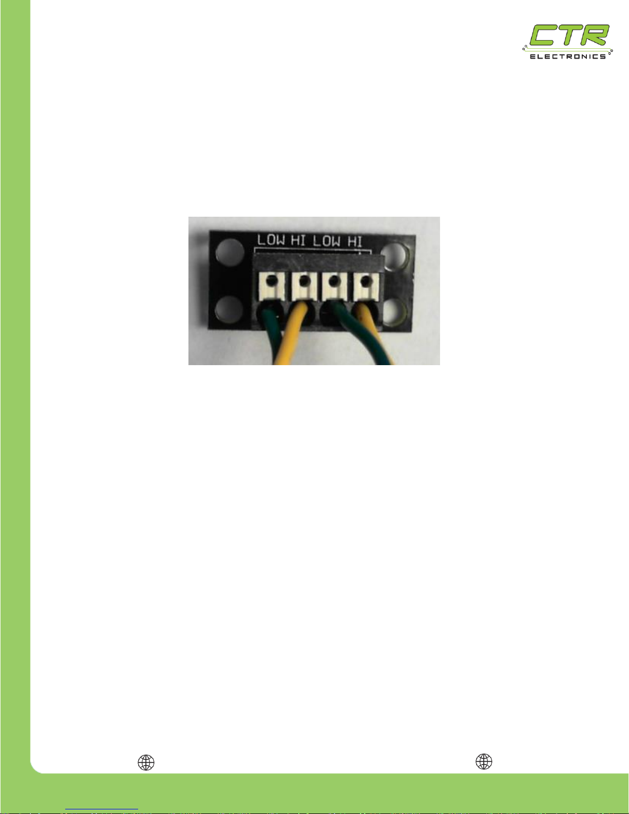
The CAN Connector can be used to chain Talon SRX’s together without crimping connectors or
soldering. Each CAN Connector contains a four channel Weidmuller terminal block with two CAN
pairs (similar to other FRC CAN devices such as the Power Distribution Panel and Pneumatic Control
Module). The four holes can be used to provide strain relief to the CAN wires. Additionally the holes
can be used for mounting to the robot frame. Spacers or electrical tape may be used to prevent
shorting to the robot frame.
1.3.2.2. CAN Bus Wire Selection
Teams should consult the FRC game rules for CAN wiring requirements. However it is
recommended to use yellow for CANH and green for CANL for the following reasons…
Makes robot inspection and troubleshooting easier.
The colors match what is labeled on the FRC Robot Controller, Power Distribution Panel,
and Pneumatic Control Module.
The colors match the Talon SRX cable harness.
AWG 22 or similar gauge wiring can be used. An electric drill can be used to twist the CANH/CANL
wire pair.
Page 12
217-8080
Talon SRX - User’s Guide
crosstheroadelectronics.com vexpro.com
Copyright 2017, Cross The Road Electronics, VEX Robotics Inc.
Updated: 2017-02-03
12
1.3.3. Wiring Talon SRX for PWM Control
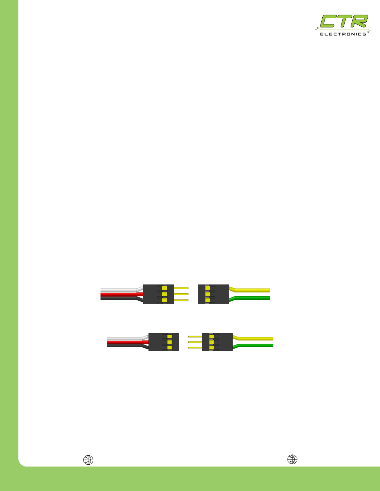
Before the Talon SRX can be controlled using a PWM signal, a standard 3-pin (0.1in pitch) PWM plug
must be connected to the Talon SRX’s signal wires. This can be done in one of two ways:
PWM housings and pins or sockets may be assembled directly on the Talon SRX’s
signal cables. If many Talon SRXs are being wired, this option will be cheaper but may
be more difficult for inexperienced users and may have a higher initial investment due
to the need of a specialized crimper.
A pre-assembled PWM cable may be cut and spliced onto the Talon SRX’s signal
wires. This option is more expensive if many Talon SRXs are being wired, but may be
easier for inexperienced users and may require a smaller initial investment.
In either case, the PWM cable should be wired such that the green (PWM ground) and yellow (PWM
signal) wires are on the outside of the PWM connector, as shown below. The center pin requires no
wire.
When purchasing components, be sure to order the correct gender PWM connector – different control
systems require different genders of PWM connectors. (The NI roboRIO requires a female PWM
connector.)
Only (2X) of the (4X) signal wires are needed to control the Talon SRX with PWM. Do Not connect
(2X) PWM connectors to a single Talon SRX. The (2X) wires that are not used for PWM control
should be electrically isolated using tape or heat shrink tubing and neatly bundled out of the way to
prevent damage.
Note: Signal wires of the same color are electrically identical – it does not matter which wire is used
as long as the color is correct.
After a PWM connector is installed, the Talon SRX will readily interface with the NI roboRIO and
many other microcontrollers. The PWM signal used to control the Talon SRX must be between 1-2ms
in duration with a center (neutral) pulse of 1.5ms and a period between 2.9-100ms.
Female 3-pin plug
required for NI roboRIO
Standard Male 3-pin
Extension Cable
Standard female 3-pin
Extension Cable
Male 3-pin plug required
for some control
Page 13
217-8080
Talon SRX - User’s Guide
crosstheroadelectronics.com vexpro.com
Copyright 2017, Cross The Road Electronics, VEX Robotics Inc.
Updated: 2017-02-03
13
Multiple Talon SRXs may be driven using a single PWM signal if a Y-Cable equivalent is used to
connect multiple PWM inputs to a single PWM output.
Note: The PWM period is how fast the robot controller can send a new PWM pulse. The amount of
time between the rising edges of two subsequent PWM pulses should not be less than 2.9ms nor
greater than 100ms.
Note: The PWM input has a logic-high minimum threshold voltage of 1.0 V. The logic-low maximum
threshold is 0.4 V. The PWM input current requirements are negligible (<1mA). This is sufficient for
most 3.3V and 5V based microcontrollers that generate PWM.
Connecting a Talon SRX to an NI roboRIO using PWM:
To connect a Talon SRX to the NI roboRIO controller, simply plug the Talon SRX’s PWM cable into
the desired PWM header in the roboRIO’s PWM output with the yellow (signal) wire on the “S” or
“inside” of the controller. The green wire will connect to the “GND” or “outside” of the controller. If an
extension cable is needed for the Talon SRX to reach the roboRIO, a standard 3-wire extension cable
should be used – these extension cables are available from VEX Robotics as well as many other
online retailers.
Page 14
217-8080
Talon SRX - User’s Guide
crosstheroadelectronics.com vexpro.com
Copyright 2017, Cross The Road Electronics, VEX Robotics Inc.
Updated: 2017-02-03
14
1.3.4. Firmware requirements (PWM and CAN bus)
Typically a Talon is shipped with firmware version 0.28. Teams should always check the FRC game
rules to determine what is the required minimum firmware version for Talon SRX (PWM / CAN bus).
Teams that utilize CAN bus will likely want to field-upgrade to the latest available firmware for the
latest features and improvements (1.1 or newer). Instructions can be found in the Software
Reference Manual. Additionally teams may need to field-upgrade to meet the minimum firmware
version in the FRC game rules.
Teams that utilize PWM may still require a firmware update if an out-of-the-box Talon has older
firmware than 0.28. Firmware that predates 0.28 will have these symptoms:
Press and holding B/C CAL Button will not enter calibration mode (red/green LED
blink).
Limit switch features not present (closing limit switches has no impact).
Boot up sequence will illuminate the B/C CAL Button for ~500ms.
1.3.4.1. PWM - Checking firmware version
As a result, it is recommended that teams using PWM first determine if a Talon has adequate
firmware by press and holding the B/C CAL button and confirming that the Talon enters calibration
mode (LEDs will blink a red/green pattern). See Section 2.2.1 for full procedure on entering
calibration mode.
IMPORTANT --- Do not drive the Talon while performing these steps unless you deliberately want to
recalibrate your Talon. For this reason, it’s best to perform this check while robot is disabled. As a
result, when you release the B/C CAL button, the Talon will blink red, indicating that it did not modify
the calibration data.
If the Talon does enter calibration mode (does blink red/green) then it has adequate firmware for
complete PWM functionality and no more steps are necessary (however FRC legality should be
checked against the game rules).
If the Talon instead just changes the brake LED (brake vs. coast) and does not enter calibration
mode then it needs to be updated once using CAN bus. See Section 1.3.4.2 for a simplified
procedure on how to do this.
Additional functional limitations of the “ship” firmware may be found in section 21 of the Talon SRX
Software Reference Manual. Although most of the limitations relate to CAN bus features, it is
recommended that teams always check section 21 for additional functional limitations that may affect
them.
Page 15
217-8080
Talon SRX - User’s Guide
crosstheroadelectronics.com vexpro.com
Copyright 2017, Cross The Road Electronics, VEX Robotics Inc.
Updated: 2017-02-03
15
1.3.4.2. PWM – Updating firmware for PWM use.
If the steps in Section 1.3.4.1 reveals that a Talon intended for PWM use has too-old firmware, field
upgrading a Talon can be done quickly with the following procedure...
Power off robot and disconnect Talon SRX from roboRIO’s PWM port if it’s connected.
Locate the free yellow/green CAN wire pair from the Talon. Since PWM-use only
requires one yellow/green wire pair, the other should be free to use.
If the roboRIO CAN bus port is in use, disconnect the CAN bus wires to free the
roboRIO’s CAN bus port. This is done be pressing the Weidmuller connector buttons
on the roboRIO and pulling out the CAN bus wires.
Insert the Talon’s free yellow/green wire pair directly into the roboRIO’s CAN bus.
Note 1: Although CAN bus requires 120Ω resistor (or PDP) at each of the two
ends of the CAN bus, when connecting a single Talon to a roboRIO for the
specific purpose of updating a single Talon, you can likely skip terminating this
end. This is because the short bus length of a single Talon, and the 120Ω resistor
integrated in the roboRIO is generally sufficient for the purpose of this procedure.
This is convenient since in this specifc case, the Talon wire pair not connected to
the roboRIO’s CAN bus port will likely have a PWM connector crimped onto it.
Power the robot on and follow the firmware update steps in the Software Reference
Manual, Section “2.3 Firmware Field-upgrade a Talon SRX”. The attached Talon
will likely have a device ID of zero. Generally it’s best to update to the latest crf file.
Disconnect the Talon SRX from roboRIO CAN bus port. If there are additional Talons
to update, go back and re-perform this procedure. Although the roboRIO and Talon
Directly to roboRIO CAN “H” Terminal
120 Ω Resistor or PDP
(Note 1)
Directly to roboRIO CAN “L” Terminal
Page 16
217-8080
Talon SRX - User’s Guide
crosstheroadelectronics.com vexpro.com
Copyright 2017, Cross The Road Electronics, VEX Robotics Inc.
Updated: 2017-02-03
16
software does not require you to power cycle the robot before re-flashing each Talon,
making wire changes while the robot is powered is a risk factor for shorting. Use best
judgment on how to safely replace the upgraded Talon with the “next” Talon to fieldupgrade.
TIP: Robot Inspectors at competition will likely check your Talons using the same steps
documented here for firmware legality, so be sure to update your competition robot
Talons before the ship date for expedient robot inspection at competition.
Page 17
217-8080
Talon SRX - User’s Guide
crosstheroadelectronics.com vexpro.com
Copyright 2017, Cross The Road Electronics, VEX Robotics Inc.
Updated: 2017-02-03
17
1.4. Wiring Sensors to the Talon SRX
1.4.1. Data Port Pinout
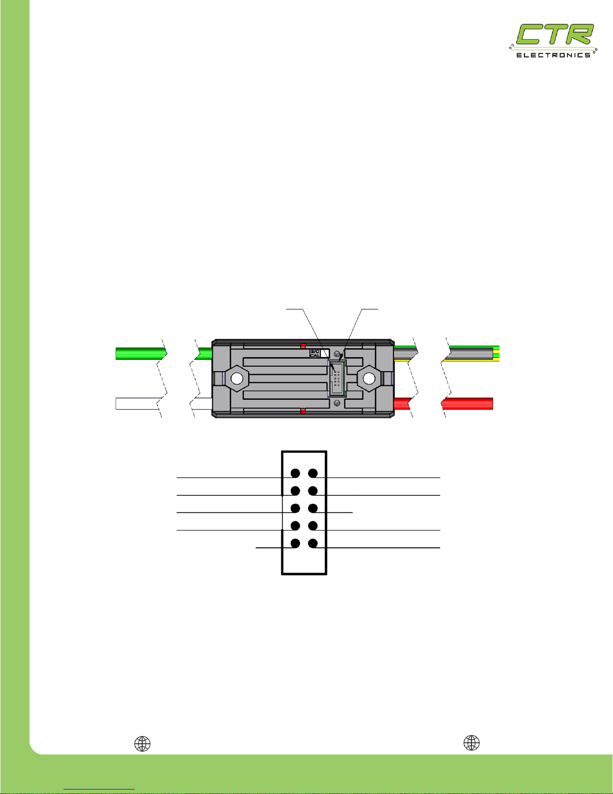
Sensors may be connected directly to the Talon SRX via the Data Port. The Talon SRX supplies the
voltage and ground to the sensor devices. Do not supply external voltages or ground into the Data
Port.
The Data Port accepts a 2x5 0.05 inch pitch keyed cable that is available from many online retailers
as well as VEX Robotics. The ribbon cable used by the Data Cable is very thin; as a result, some
teams may find a breakout board helpful when wiring sensors.
Note: Leave unused Data Port Pins floating.
+3.3V 1
Analog Input 3
Quadrature B 5
Quadrature A 7
X
2 +5V
4 Forward Limit
8 Reverse Limit
10 GND
X
9
Data Port Pinout
6 DO NOT CONNECT
Pin 1
Data Port
Quadrature Index
Page 18
217-8080
Talon SRX - User’s Guide
crosstheroadelectronics.com vexpro.com
Copyright 2017, Cross The Road Electronics, VEX Robotics Inc.
Updated: 2017-02-03
18
1.4.2. Analog Input
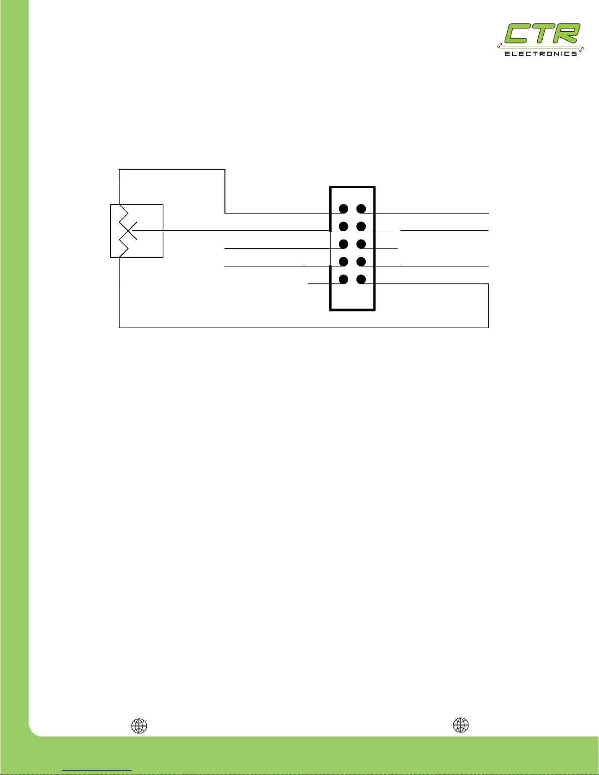
Attach the analog sensor as shown. Do not connect the GND line elsewhere. Only use 3.3V as the
analog sensor voltage source. Although the figure explicitly shows a potentiometer, a 3.3V Analog
Encoder can also be wired similarly.
+3.3V 1
Analog Input 3
Quadrature B 5
2 +5V
10 GND
Quadrature A 7
X
Quadrature Index 9
4 Forward Limit
6 DO NOT CONNECT
Analog Sensor Input
X
8 Reverse Limit
Analog
Sensor
Page 19
217-8080
Talon SRX - User’s Guide
crosstheroadelectronics.com vexpro.com
Copyright 2017, Cross The Road Electronics, VEX Robotics Inc.
Updated: 2017-02-03
19
1.4.3. Quadrature Encoder Input
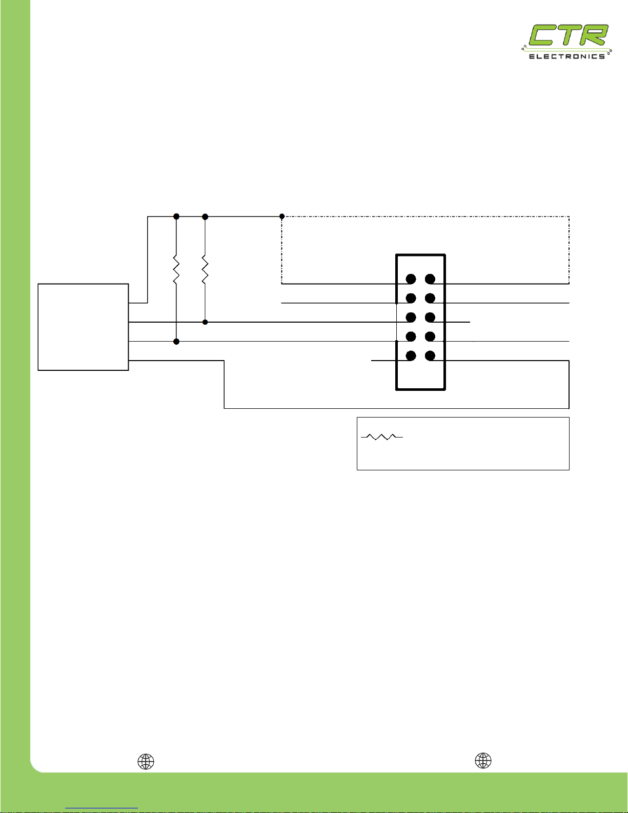
Attach the Quadrature Encoder as shown. Do not ground the GND line elsewhere. Connect either
the 3.3V or 5.0V as required by your sensor. DO NOT CONNECT THE 3.3V OUTPUT TO THE 5V
OUTPUT. Some encoders may have an Index pin. Talon supports counting the rising edges on the
Index rail so that robot controller can react to it. However wiring index is not required for decoding the
position and velocity of the encoder.
X
Quadrature Index 9
(Not required)
+3.3V 1
Analog Input 3
Quadrature B 5
Quadrature A 7
2 +5V
4 Forward Limit
6 DO NOT CONNECT
8 Reverse Limit
10 GND
Quadrature Encoder Input
Quadrature
Encoder
Optional 10k Pull Up
Resistor if required by
sensor
X
Page 20
217-8080
Talon SRX - User’s Guide
crosstheroadelectronics.com vexpro.com
Copyright 2017, Cross The Road Electronics, VEX Robotics Inc.
Updated: 2017-02-03
20
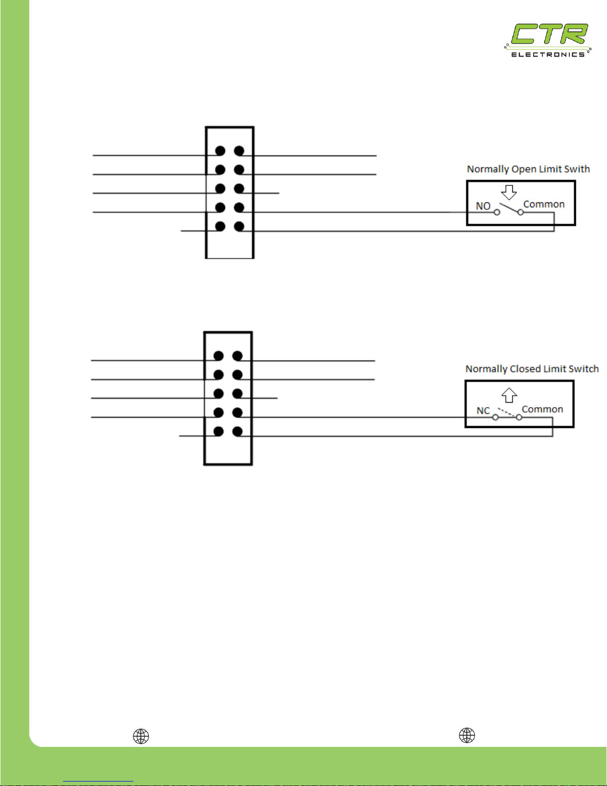
1.4.4. Forward & Reverse Limit Switch Inputs
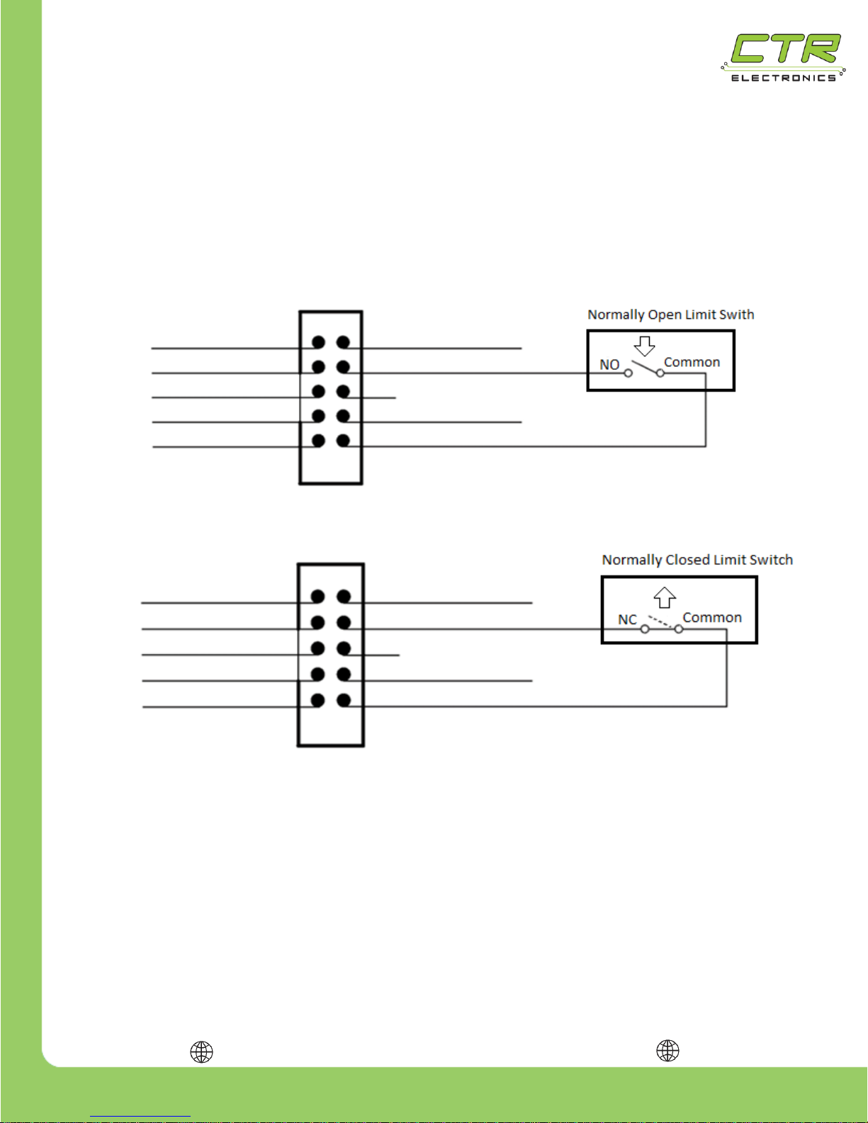
Attach the Forward/Reverse Limit Switch as shown. Do not connect the GND elsewhere. The Talon
SRX provides a pull-up to 2.5v, so typically an external pull-up is not needed. Only use Talon SRX
3.3V or 5.0V power if an external pull-up is used. The default setting of “Normally Open” ensures an
“out of the box” Talon SRX functions even if no limit switch is connected. See the Software
Reference Manual to change the default Limit Switch behavior from “Normally Open”.
+3.3V 1
Analog Input 3
Quadrature B 5
Quadrature A 7
2 +5V
4 Forward Limit
6 DO NOT CONNECT
X
8 Reverse Limit
10 GND
Quadrature Index 9
Forward Limit Switch - Normally Open (default)
Forward Limit Switch - Normally Closed
+3.3V 1
Analog Input 3
Quadrature B 5
Quadrature A 7
2 +5V
4 Forward Limit
6 DO NOT CONNECT
X
8 Reverse Limit
10 GND
Quadrature Index 9
Page 21
217-8080
Talon SRX - User’s Guide
crosstheroadelectronics.com vexpro.com
Copyright 2017, Cross The Road Electronics, VEX Robotics Inc.
Updated: 2017-02-03
21
Reverse Limit Switch - Normally Closed
+3.3V 1
Analog Input 3
Quadrature B 5
Quadrature A 7
2 +5V
4 Forward Limit
6 DO NOT CONNECT
X
8 Reverse Limit
10 GND
Quadrature Index 9
+3.3V 1
Analog Input 3
Quadrature B 5
Quadrature A 7
2 +5V
4 Forward Limit
6 DO NOT CONNECT
X
8 Reverse Limit
10 GND
Quadrature Index 9
Reverse Limit Switch - Normally Open (default)
Page 22
217-8080
Talon SRX - User’s Guide
crosstheroadelectronics.com vexpro.com
Copyright 2017, Cross The Road Electronics, VEX Robotics Inc.
Updated: 2017-02-03
22
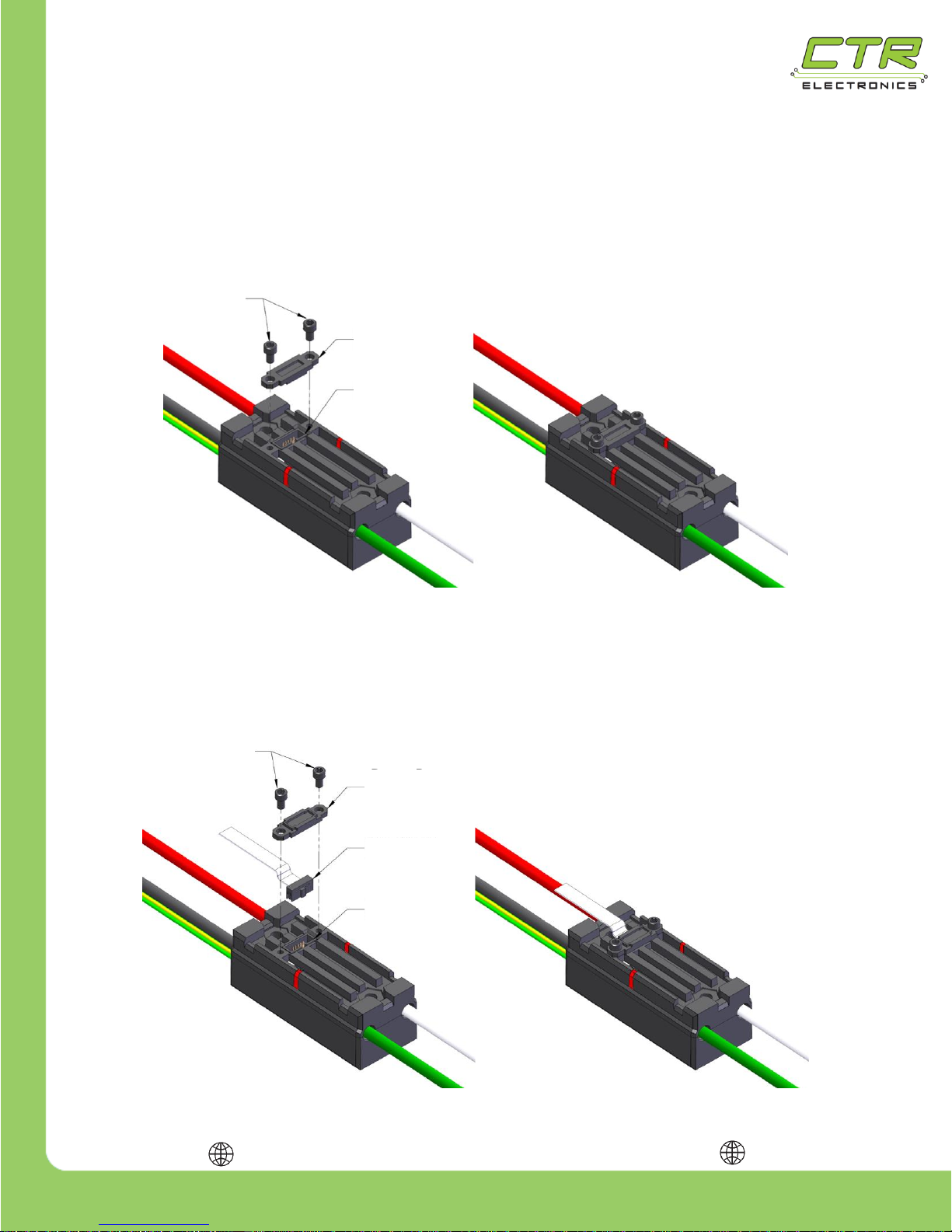
1.4.5. Connecting to the Data Port
To maintain a sealed case, the Talon SRX includes a plastic cover for the Data Port. When the port is
not being used, the plastic cover should be installed on the case, as shown below, to protect the pins
from foreign objects. When installing the cover, be sure to note its orientation.
To use the Data Port, a 2x5 0.05 inch pitch connector should be wired as detailed in the previous
sections and plugged in as shown below. After the connector is plugged it, the plastic cover may be
used to retain the connector, as shown below – be sure to note the plastic cover’s orientation.
(2X) #4-40 x 3/16in
Socket Cap Screws
Data Port
Cover
Data Port
Data Cable
Data Port
Cover
Data Port
(2X) #4-40 x 3/16in
Socket Cap Screws
Page 23
217-8080
Talon SRX - User’s Guide
crosstheroadelectronics.com vexpro.com
Copyright 2017, Cross The Road Electronics, VEX Robotics Inc.
Updated: 2017-02-03
23
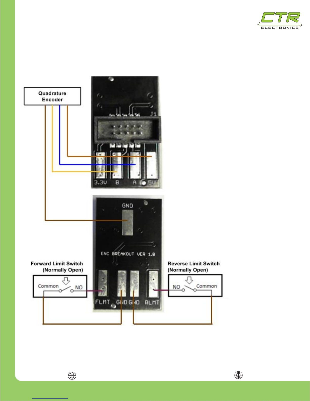
1.4.6. Encoder (and Limit Switch) Breakout
The Encoder Breakout makes breaking out the encoder and limit switch pins even easier.
Part Numbers: CTRE_ENC_BRK, 217-4398(vexrobotics.com), am-2633(andymark.com)
The top side of the breakout has the same
data port pinout as the Talon SRX. A
ribbon cable should be used to connect the
Talon SRX to the breakout.
Top side solder pads are broken out for
3.3V, 5V, and Quadrature A and B.
Tip: The selected colors in the diagram
match the cable harness colors for some
U.S. Digital Quadrature Encoders.
Although 5V is used in this example, 3.3V
should be used for 3.3V encoders. Always
check the encoder data sheet for voltage
requirements.
On the bottom side of the breakout are
three ground pads and the two pads for
forward and reverse limit switch inputs.
Although normally open switches are
illustrated, normally closed switches can
also be used.
Page 24
217-8080
Talon SRX - User’s Guide
crosstheroadelectronics.com vexpro.com
Copyright 2017, Cross The Road Electronics, VEX Robotics Inc.
Updated: 2017-02-03
24
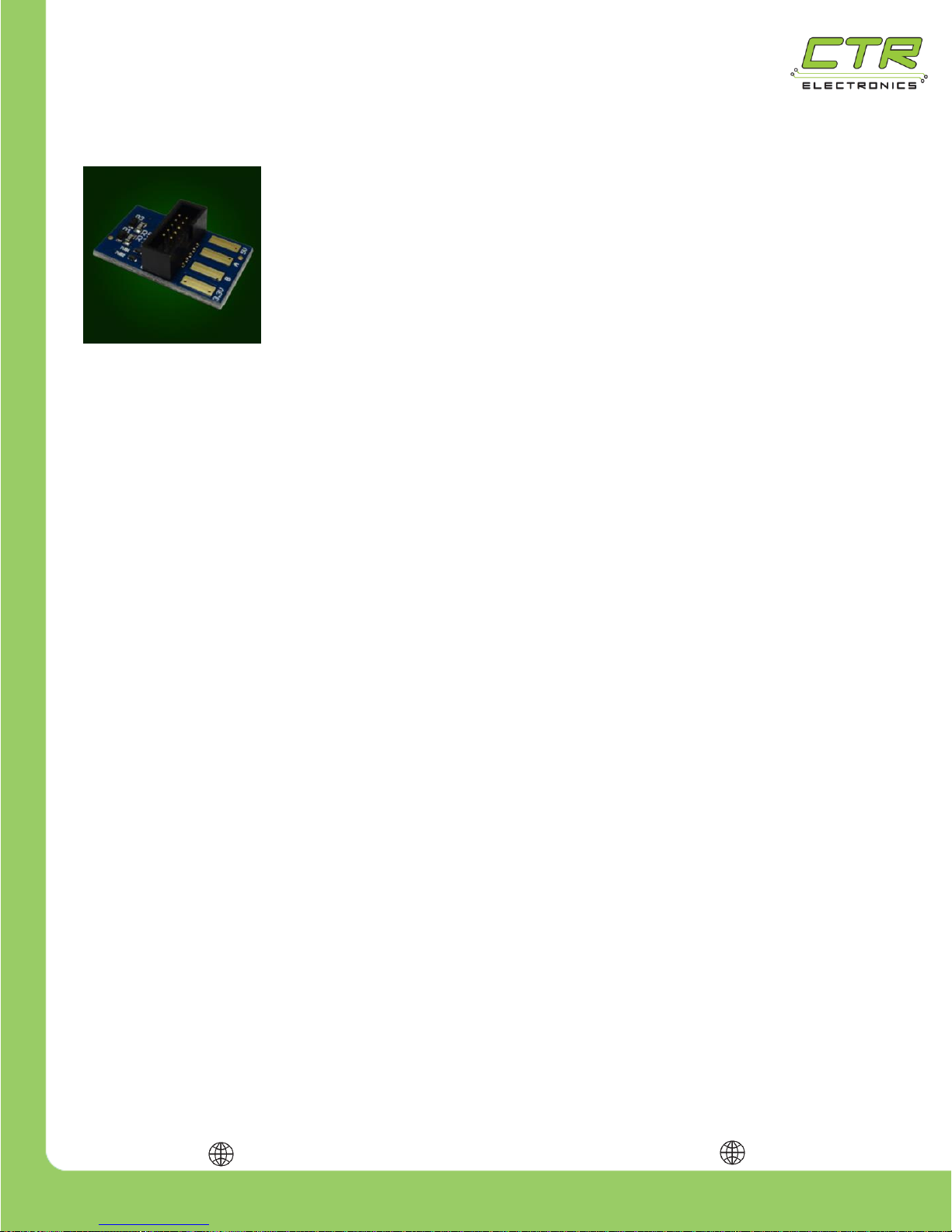
1.4.6.1. Encoder (and Limit Switch) Breakout – Blue Revision
The latest revision of the Talon SRX Encoder Breakout Board has
additional level shifting to ensure proper operation with 5V Quadrature
sensors, regardless of Talon SRX hardware revision (see
Electrical/Mechanical Specs – Note 1). These boards are easy to identify
as they are blue.
NOTE: Quad A and Quad B are reversed on this revision. Users
intending to use features that require the Talon’s Quad A pin should wire to
the Breakout’s Quad B pad (Rising Edge Counter for example).
Additionally, migrating from the black to blue revision will cause the sensor
direction orientation to change.
Page 25
217-8080
Talon SRX - User’s Guide
crosstheroadelectronics.com vexpro.com
Copyright 2017, Cross The Road Electronics, VEX Robotics Inc.
Updated: 2017-02-03
25
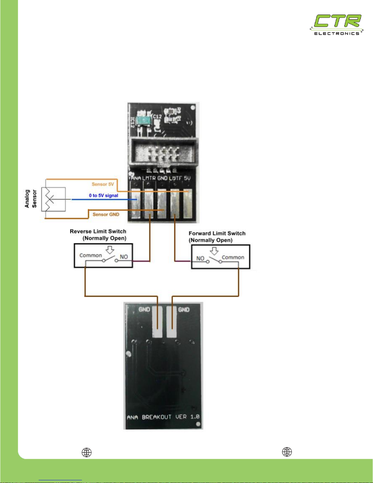
1.4.7. Analog 5V Encoder (and Limit Switch) Breakout
The Analog 5V Breakout is for wiring a 5V analog sensor and limit switches. What makes this
breakout unique is that it scales a 5V analog signal to 3.3V using a resistor divider and voltage buffer.
Part Number: 217-4401(vexrobotics.com), am-2634(andymark.com)
5V Magnetic Shaft Encoders like the
U.S. Digital MA3 “just work” since the
breakout shifts the encoders native 5V
output to a Talon SRX compliant 3.3V
signal.
The top side has the 5V power, signal,
and ground pads for the analog sensor.
A ribbon cable should be used to
connect the Talon SRX to the breakout.
Tip: The selected colors in the diagram
match a typical cable harness colors for
some U.S. Digital Magnetic Encoders.
Additionally, the limit switch
pads are also available on
the top side. Note that the
reverse limit switch is on the
left side.
On the bottom are two additional ground
pads to pair with the limit switch pads.
Although normally open switches are
illustrated, normally closed switches can
also be used.
Page 26
217-8080
Talon SRX - User’s Guide
crosstheroadelectronics.com vexpro.com
Copyright 2017, Cross The Road Electronics, VEX Robotics Inc.
Updated: 2017-02-03
26
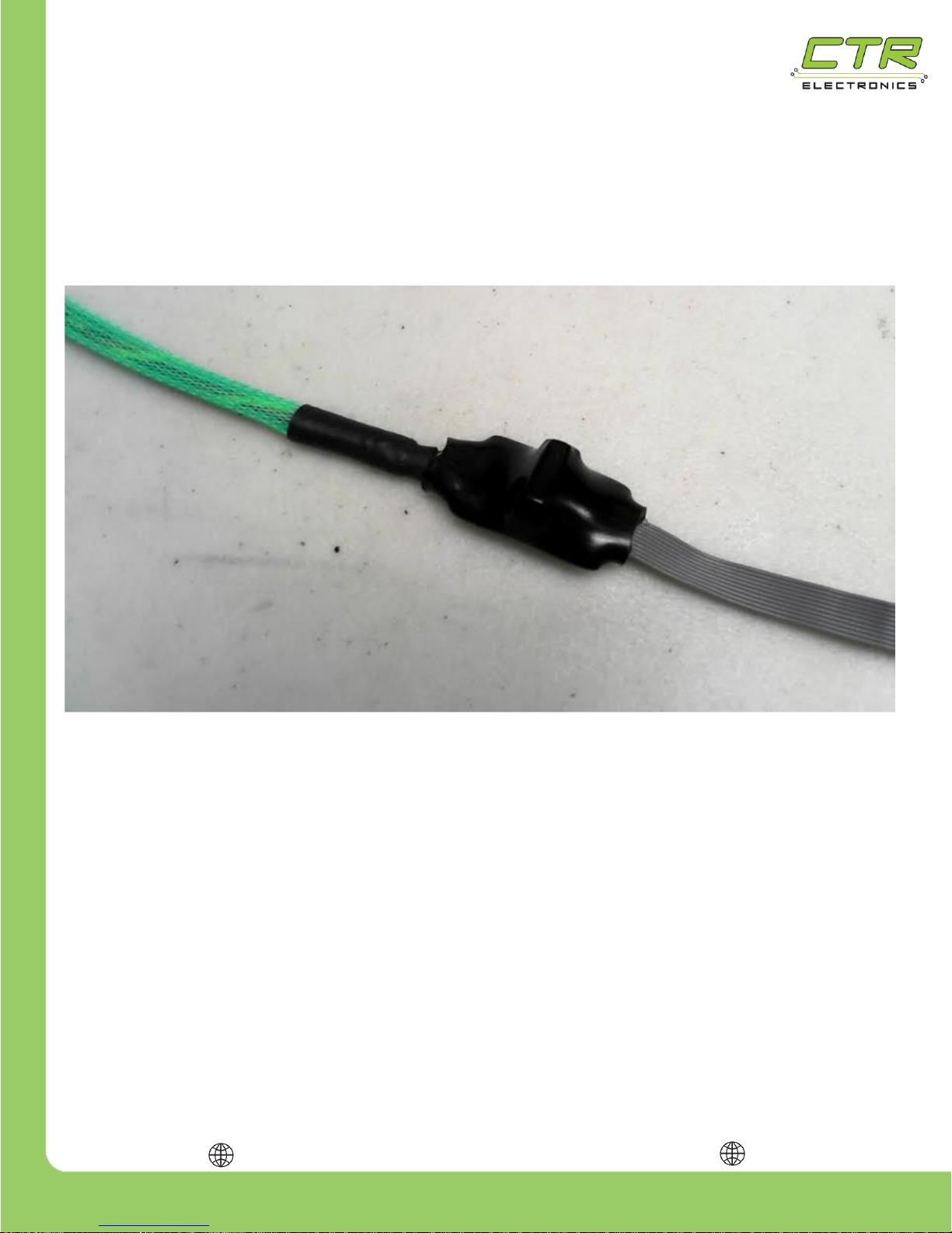
1.4.8. Heat Shrink Use with Breakout
Another advantage to using the Quadrature or Analog Encoder Breakout is that they are designed to
be encapsulated with large diameter heat shrink. This ensures that there is no risk of shorting the
breakout to robot frame (or other conductive surfaces). This method works particularly well when
using a wire loom (green loom in example below).
Page 27
217-8080
Talon SRX - User’s Guide
crosstheroadelectronics.com vexpro.com
Copyright 2017, Cross The Road Electronics, VEX Robotics Inc.
Updated: 2017-02-03
27
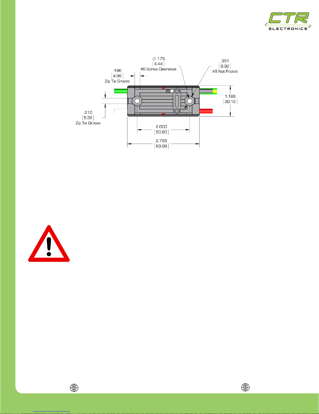
1.5. Mounting the Talon SRX
The Talon SRX can be mounted using either (2X) #8-32 screws or zip-ties. The Talon SRX’s
aluminum case is electrically isolated from the electronics, meaning it is safe to mount directly to a
robot’s frame!
The Talon SRX’s mounting location should be chosen to allow for adequate air flow around the heat
fins and sides of the case. For maximum heat dissipation it is recommended that the Talon SRX be
securely mounted to a robot’s metal frame – this allows the robot to be used as a giant heat sink to
aid in cooling.
CAUTION: IN RARE CIRCUMSTANCES, THE TALON SRX MAY BECOME
HOT DURING USE. USE CAUTION AROUND ANY TALON SRX THAT HAS
RECENTLY BEEN USED, ESPECIALLY ONES USED FOR HIGH CURRENT
APPLICATIONS. IF PROTECTED BY A 40A BREAKER, THE TALON SRX MAY
BECOME HOT BUT WILL NOT BECOME HOT ENOUGH TO DAMAGE ITSELF.
1.6. General Robot Wiring Guidelines
An important (yet frequently forgotten) aspect of wiring is strain relief. All electrical connections should
be isolated from any pulling or tugging that may result in a poor connection. Once the Talon SRX is
fully wired, zip ties should be used to ensure that all electrical connections are protected.
Note: When zip tying wires down, it is crucial to avoid sharp edges on the robot. Wires that are
anchored to sharp edges can become worn over time and cause a short.
Page 28
217-8080
Talon SRX - User’s Guide
crosstheroadelectronics.com vexpro.com
Copyright 2017, Cross The Road Electronics, VEX Robotics Inc.
Updated: 2017-02-03
28
1.7. Applying Power for the First Time
Before applying power for the first time, it is a good idea to double check the following:
The red wire is connected to the positive source.
The black wire is connected to the source ground.
All electrical connections are secure and electrically isolated (wrapped in electrical tape,
heat shrink tubing or similar).
A 40A or smaller breaker is in series with the Talon SRX’s positive power input.
There are no short circuits on the Talon SRX’s output.
If using CAN bus to control Talon SRXs, it is a good idea to double check the following:
A unique ID has been assigned to each Talon SRX.
A yellow signal wire is plugged into the “H” terminal of the CAN controller.
A green signal wire is plugged into the “L” terminal of the CAN controller.
The CAN bus has two “ends” each ending in either the roboRIO, the PDP (with the
termination resistor jumper placed in the ON position), or a 120 Ω resistor.
If the PDP is not at the end of the CAN bus, its termination resistor jumper should be in the
OFF position, and an explicit 120 Ω resistor should be present at the end of the bus.
If using a PWM signal to control Talon SRXs, it is a good idea to double check the following:
The PWM connector is wired as shown on page 10.
The PWM connector is plugged in with the correct orientation.
The spare Yellow and Green wires of the twisted pair are electrically insulated from each
other.
The Talon SRX automatically checks for valid PWM or CAN bus on power up. No
additional configuration is necessary.
Page 29
217-8080
Talon SRX - User’s Guide
crosstheroadelectronics.com vexpro.com
Copyright 2017, Cross The Road Electronics, VEX Robotics Inc.
Updated: 2017-02-03
29
2. Additional Information
2.1. Brake & Coast Modes
The Talon SRX has two modes: Brake and Coast. When a neutral signal is applied to the Talon SRX
in Brake mode, the motor will resist rotation, especially high speed rotation. This is accomplished by
essentially shorting the motor leads together, which causes a Back Electromotive Force (Back-EMF)
to resist the rotation of the motor. Brake mode does not have any effect when the motor is not rotating,
but can make a large difference in robot behavior when used on a motor attached to a high reduction
gearbox. Brake mode does not impact performance when the motor is being driven by the Talon SRX.
When a neutral signal is applied to the Talon SRX in Coast mode, Back-EMF will not be generated,
so the motor’s rotation will not be affected by the Talon SRX.
An added feature of the Talon SRX is its ability to toggle between Brake & Coast modes during
operation using CAN bus.
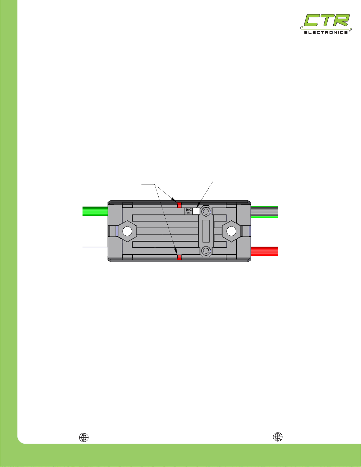
2.1.1. Switching Between Brake & Coast Using the B/C CAL
Button:
To switch between Brake and Coast mode, simply push the B/C CAL button at any time. The Talon
SRX is in Brake mode when the button is illuminated red and Coast when the red light is turned off.
Brake/Coast settings are saved even if power is removed from the Talon SRX.
2.1.2. Switching Between Brake & Coast Using CAN bus:
Use the roboRIO Web-based Configuration page for CAN selection between Brake and Coast Modes.
2.1.3. Switching Between Brake & Coast Using CAN Control
Frames
Each supported programming language includes an API that allows active switching between Brake &
Coast modes during a match. See Software Reference Manual for more information.
Page 30
217-8080
Talon SRX - User’s Guide
crosstheroadelectronics.com vexpro.com
Copyright 2017, Cross The Road Electronics, VEX Robotics Inc.
Updated: 2017-02-03
30
2.2. PWM Calibration
The PWM calibration of a Talon SRX determines how to scale the PWM input signal to output voltage.
Different controllers may have different “max” and “min” PWM signals that may not correspond to the
same Talon SRX outputs. Calibrating the Talon SRX allows it to adjust for these differences so that a
“max” signal results in a “max” output. Calibrating can also correct issues caused by joysticks or
gamepads with off-center neutral outputs. The Talon SRX’s default calibration is compatible with the
NI roboRIO control system.
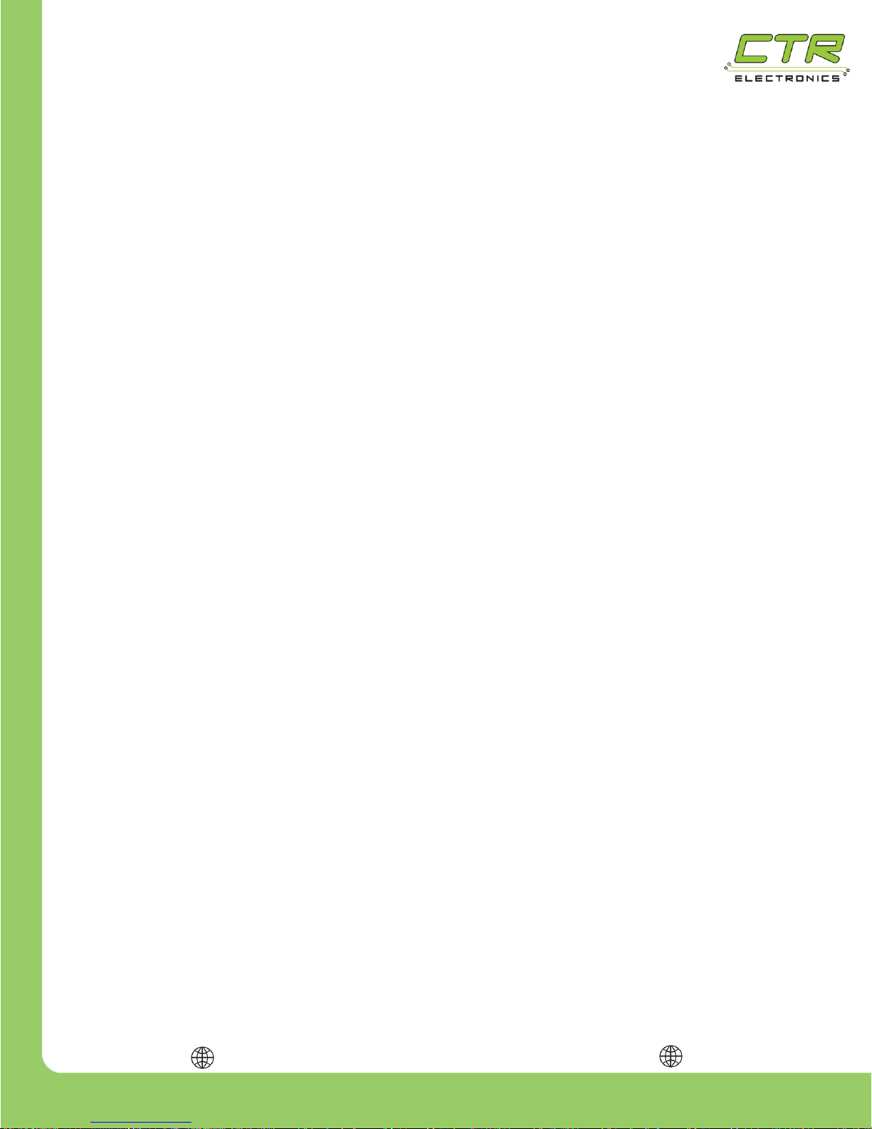
2.2.1. To Calibrate the Talon SRX:
1) Press and hold the B/C CAL button until the Status LEDs begin to rapidly blink red & green.
2) While holding the button, move the joystick (or other input signal) to full forward then to full
reverse. This can be done multiple times. The Talon SRX is looking for max & min PWM
values during this step, so ensure that the joystick reaches its full max and full min.
3) Release the joystick and allow it to return to neutral. After the joystick is in the neutral
position, release the B/C CAL button.
4) If the Talon SRX was calibrated properly, the status LEDs will blink green several times.
If the calibration failed, the status LEDs will blink red and the previous calibration will be
kept.
Note: Calibration profiles are saved to persistent memory (persist across power cycles)
Status
B/C CAL
Button
Page 31
217-8080
Talon SRX - User’s Guide
crosstheroadelectronics.com vexpro.com
Copyright 2017, Cross The Road Electronics, VEX Robotics Inc.
Updated: 2017-02-03
31
2.2.2. To Restore Default Calibration:
1) Remove power from the Talon SRX
2) Hold the B/C CAL button down
3) While holding down the button, restore power to the Talon SRX
4) Continue holding the button until the status LEDs blink green then release the button
Page 32
217-8080
Talon SRX - User’s Guide
crosstheroadelectronics.com vexpro.com
Copyright 2017, Cross The Road Electronics, VEX Robotics Inc.
Updated: 2017-02-03
32
2.3. Blink Codes
Blink Codes During Calibration
Status LEDs Blink
Code
Talon SRX State
Flashing Red/Green
Calibration Mode
Blinking Green
Successful Calibration
Blinking Red
Failed Calibration
B/C CAL Blink Codes
B/C CAL Button Color
Talon SRX State
Solid Red
Brake Mode
Off
Coast Mode
1: LEDs Alternate – Status LEDs are different colors at all times. The (2X) LEDs will swap colors
when blinking.
2: (1X) Status LED will blink followed shortly by the other with a long pause before repeating. The
“direction” of the blink indicates the Talon SRX’s current state.
Blink Codes During Normal Operation
LEDs
Colors
Talon SRX State
Both
Blinking Green
Forward throttle is applied.
Blink rate is proportional to Duty Cycle
Both
Blinking Red
Reverse throttle is applied.
Blink rate is proportional to Duty Cycle
None
None
No Power is being applied to Talon SRX
LEDs Alternate
1
Off/Orange
CAN bus detected, robot disabled
LEDs Alternate
1
Off/Red
CAN bus/PWM is not detected
LEDs Alternate
1
Switching between
Red/Orange and
Orange/Red
Damaged Hardware
LEDs Strobe
“towards” (M+)
2
Off/Red
Forward Limit Switch or Forward Soft Limit
LEDs Strobe
“towards” (M-)2
Off/Red
Reverse Limit Switch or Reverse Soft Limit
LED1 Only
“closest” to
M+/V+
Green/Orange
In Boot-loader
Both
Solid Orange
Neutral throttle is applied.
Throttle is zero or is within dead band.
Page 33
217-8080
Talon SRX - User’s Guide
crosstheroadelectronics.com vexpro.com
Copyright 2017, Cross The Road Electronics, VEX Robotics Inc.
Updated: 2017-02-03
33
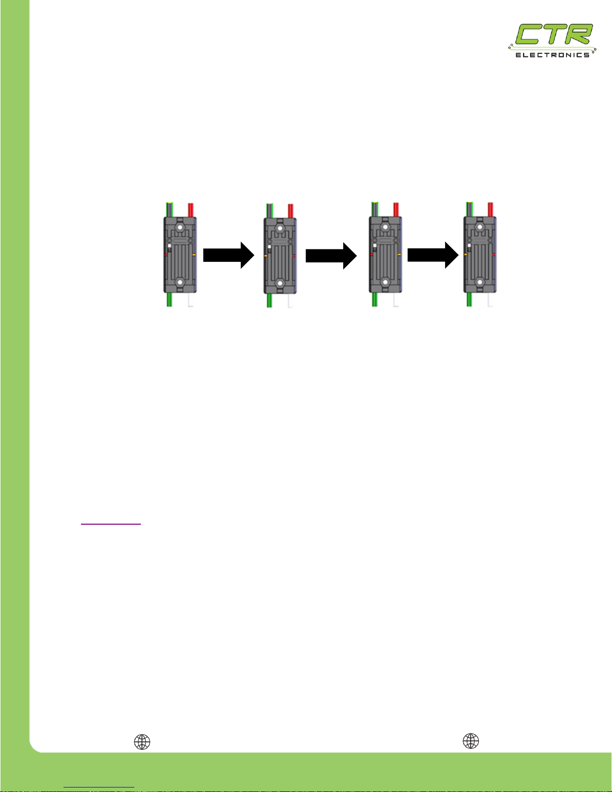
2.3.1. Blink Codes – Damaged Hardware
The Talon SRX can detect certain types of hardware damage. When damage is detected the Talon
will blink in a periodic fashion as mentioned in the table above.
This is also illustrated below…
This failure mode typically occurs after reverse powering the input power leads (red and black) or by
providing battery voltage through the motor leads (green/white leads). Both will cause
permanent damage and must be prevented.
Note that the LEDs never turn off when indicating this failure mode. Each LED is always red or
orange at any moment. The orange/red LED pattern will continue to blink this pattern with no
intermittent change in LED activity.
If this is being witnessed, ensure that the LED pattern isn’t simply an intermittent red LED blink
superimposed on to the typical orange LED pattern. This is typically observed when there is an
intermittent wiring issue or when two or more Talons with common device IDs are present on the
CAN bus. Both can be checked by connecting the Talon directly to the robot controller following the
steps in Section 1.3. Do not connect any other CAN devices and avoid complex wire harness
strategies.
Erratic red and orange blink patterns are typically caused by intermittent cable issues, or not properly
configuring the device IDs of the Talon SRX. Such LED patterns should not be misconstrued as the
damaged LED code mentioned above.
This is also supplemental content covered in the Talon SRX Software Reference Manual under
Section 16 – Troubleshooting Tips and Common Questions.
Page 34
217-8080
Talon SRX - User’s Guide
crosstheroadelectronics.com vexpro.com
Copyright 2017, Cross The Road Electronics, VEX Robotics Inc.
Updated: 2017-02-03
34
2.4. Performance Data
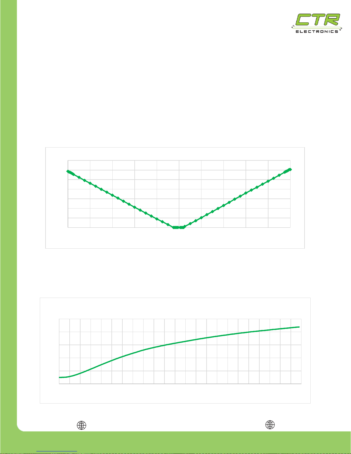
The Talon SRX was designed to provide a predictable linear response over a wide range of PWM
signals. To demonstrate its linearity, an experiment was performed by using a calibrated Talon SRX
controlled by a VEX Arm® Cortex®-based Microcontroller to drive a Mini CIM motor under no load.
The PWM signal was varied from -100% to 100% at regular intervals. Finer intervals were measured
near -100%, 0% and 100% duty cycle. During the test, the PWM signal and Mini CIM output were
recorded and plotted, as shown below.
Note: This plot should only be used to evaluate the linearity of the Talon SRX’s output. This
plot should not be used to predict a motor’s behavior at a specific input signal.
To evaluate the Talon SRX’s thermal performance, a 40A load was applied using CIM motors and a
dynamometer. Before the test, a thermocouple was attached to the top of the Talon SRX. The test
was run for 10 minutes with temperature data being recorded at one second intervals then plotted, as
shown below.
0
1000
2000
3000
4000
5000
6000
7000
-100 -80 -60 -40 -20 0 20 40 60 80 100
Mini CIM RPM
PWM Signal (% Duty Cycle)
CIM RPM vs PWM Signal
70
90
110
130
150
170
0 1 2 3 4 5 6 7 8 9 10 11 12 13 14 15 16 17 18 19 20 21 22 23
Temp (°F)
Time (Min)
Temp vs Time
100% Duty Cycle, 40A Continuous Load
Page 35
217-8080
Talon SRX - User’s Guide
crosstheroadelectronics.com vexpro.com
Copyright 2017, Cross The Road Electronics, VEX Robotics Inc.
Updated: 2017-02-03
35
2.5. Frequently Asked Questions:
Q: Is it possible to use more than one type of speed controller?
A: Yes, it is completely safe and acceptable to use multiple types of speed controllers (e.g.
Victors & Talons) on a single robot.
Q: Is it safe to mount a Talon SRX directly to a robot’s metal frame?
A: Yes, the electronics inside the Talon SRX are separated from the case by two different
layers of electrical insulation to prevent case shorts.
Q: Does the Talon SRX require a fan?
A: The Talon SRX does not require a fan for typical FRC use but if the robot is being used for
practice or many back to back matches it is a good idea to use a fan to cool the Talon SRX to
prevent accidental burns.
Q: Can the Talon SRX be used with control systems other than the NI roboRIO?
A: Yes, the Talon SRX may be used with any control system that is capable of CAN bus or
PWM output.
Q: What kind of electrical connectors should I use to connect wires to the Talon SRX?
A: The choice of electrical connectors is left to the user. Electrical connectors should be
appropriately sized for the wire used and current requirements. For the best electrical
connection, it is highly recommended that wire connectors are soldered to the wire after they
are crimped on.
Q: There are (2X) yellow & (2X) green input signal wires. How do I know which one to use?
A: Signal wires of the same color are electrically identical – it does not matter which wire is
used as long as the color is correct.
Q: Can two Talon SRXs drive the same motor?
A: No. DO NOT connect the outputs of two Talon SRXs together. Damage will likely occur.
Q: Can a single PWM output be used to drive (2X) Talon SRXs?
A: Yes. Two or more Talon SRXs may be driven using a single PWM signal if a 3-wire Y-Cable
is used.
Page 36
217-8080
Talon SRX - User’s Guide
crosstheroadelectronics.com vexpro.com
Copyright 2017, Cross The Road Electronics, VEX Robotics Inc.
Updated: 2017-02-03
36
Q: Will un-powering a Talon SRX in the middle of a daisy-chained CAN bus cause a problem?
A: No. This does not prevent communication with the remaining Talons on the CAN bus. Both
yellow wires are electrically-common, as is the green wires. Power is not required to forward
the CAN signals.
Q: My Talon SRX is blinking the hardware-damaged code. What next?
A: Follow the recommendations under Section 2.3.1.
Page 37
217-8080
Talon SRX - User’s Guide
crosstheroadelectronics.com vexpro.com
Copyright 2017, Cross The Road Electronics, VEX Robotics Inc.
Updated: 2017-02-03
37
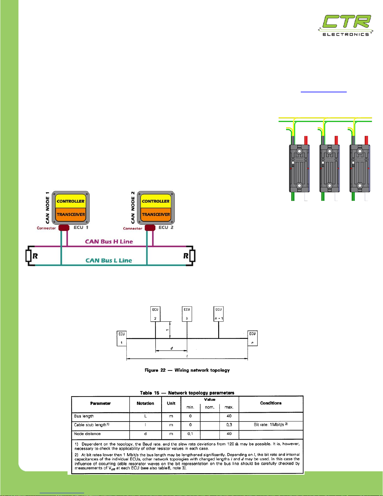
Q: What CAN bus topologies are recommended?
A: The Talon is intended to be used in the daisy chain fashion explained in Section 1.3.2.
Additionally, FRC Teams should always confirm what is considered “legal” per latest FRC
competition rules.
Alternatively, the CAN bus may be wired in the fashion commonly
seen in the automotive industry where a single harness is made
(with proper termination resistor at each of the two ends). Each
module can “tap” into the primary bus harness (crimp, connector,
soldered, etc.) with a cable stub (maximum length of one foot).
In the automotive industry, this is accomplished
with a cable design that has the cable stubs
designed in with end-connectors at various
places in the cable.
As documented in the DW CAN bus specification, both daisy chain or a designed master cable
harness meets the specification’s documented topology (diagram below).
Page 38
217-8080
Talon SRX - User’s Guide
crosstheroadelectronics.com vexpro.com
Copyright 2017, Cross The Road Electronics, VEX Robotics Inc.
Updated: 2017-02-03
38
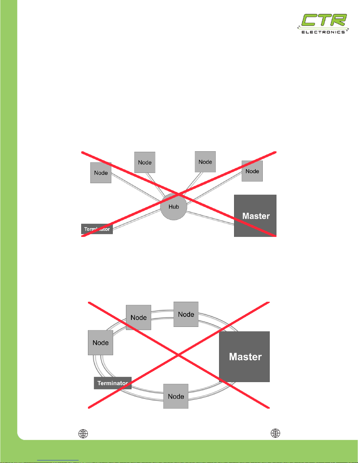
Star topology is not recommended. This use case is not common, nor is it suggested in
the DW CAN bus specification. This nonstandard implementation requires careful study
and analysis of the candidate bus cable, which is typically beyond the capabilities of a
typical FRC team.
This topology may be used when performing basic testing on a bench-setup with a small
network (few modules and short cable travel). However, this use case should not be
construed as evidence guaranteeing that star topology is a robust solution. Star topology
is not a robust general solution to be relied on for critical applications.
Ring topology is not recommended. This use case is not common, nor is it suggested in
the DW CAN bus specification. This nonstandard implementation requires careful study
and analysis of the candidate bus cable, which is typically beyond the capabilities of a
typical FRC team.
Page 39
217-8080
Talon SRX - User’s Guide
crosstheroadelectronics.com vexpro.com
Copyright 2017, Cross The Road Electronics, VEX Robotics Inc.
Updated: 2017-02-03
39
3. Troubleshooting
Indication: Both LEDs alternate red & orange
Problem: Damaged Hardware – the device requires service
Solution:
Contact CTRE (crosstheroadelectronics.com). The Talon SRX is not warranted for use until
the hardware is repaired. DO NOT attempt to use the Talon SRX.
Indication: Single LED alternates green & orange
Problem: The device is in Boot-loader Mode
Solution:
1) Download the latest firmware from crosstheroadelectronics.com
2) Follow directions in the Software Reference Manual to field upgrade the Talon SRX.
Indication: No LEDs are illuminated
Problem: No Power
Check the Following:
1) Is the robot battery is connected?
2) Is the main breaker is turned on?
3) Is the Talon SRX is connected to the Power Distribution Panel (PDP)?
4) Are any wires are broken or shorted?
Indication: Both LEDs slowly alternate between red & off
Problem: CAN/PWM is not detected
Check the Following:
1) If the robot is using PWM, is the robot disabled?
2) If the robot is using PWM, is the PWM cable unplugged?
3) If the robot is using CAN, is the CAN cable plugged in?
4) If the robot is using CAN, is the terminator resistor correctly wired?
Page 40
217-8080
Talon SRX - User’s Guide
crosstheroadelectronics.com vexpro.com
Copyright 2017, Cross The Road Electronics, VEX Robotics Inc.
Updated: 2017-02-03
40
Indication: Both LEDs quickly blink red then off.
First one LED blinks red, followed immediately by the other,
then finally both LEDs are off for a small period of time.
Problem: Limit Switch or Soft Limit Activated
Possible Solutions:
1) The most likely cause is a limit switch or soft limit fault. Test each limit switch by opening &
closing it manually.
2) Use the roboRIO Web-based Configuration page to retrieve information over CAN bus
about the Limit Switch state. See Software Reference Manual for more information.
3) The roboRIO Web-based Configuration page can set soft limits over CAN bus. The soft
limits will be applicable with CAN control.
Indication: Both LEDs slowly alternate between orange and off.
Problem: CAN bus detected but the Talon SRX is disabled or not being addressed over CAN.
Possible Solution:
Use the roboRIO Web-based Configuration page to retrieve information over CAN bus about
the fault. Most likely the device ID of that Talon is not being used. There must be an Open
Motor (LabVIEW ®) or constructed CANTalon (C++/Java) with that device ID.
This can also be confirmed by doing a Self-Test in the roboRIO Web-based Configuration. If
the “TALON IS NOT ENABLED!” message appears even though the robot is enabled, then
recheck the device IDs in the robot application.
Indication: Flashing RED Status LEDs after calibration.
Problem: Calibration Failed.
Possible Solutions:
1. Inadequate travel in either the forward or reverse direction. Repeat the calibration
procedure and move the joystick further forward and/or further reverse.
2. The joystick trim is not centered. Neutral cannot be extremely far from center.
Page 41
217-8080
Talon SRX - User’s Guide
crosstheroadelectronics.com vexpro.com
Copyright 2017, Cross The Road Electronics, VEX Robotics Inc.
Updated: 2017-02-03
41
Indication: No power output from the speed controller although the Status LEDs work.
Problem: Possible internal damage.
Possible Solutions:
If the Status LEDs on the Talon SRX are operating properly and there is no output, the Talon
SRX may be internally damaged. This condition is typically caused by a short circuit on the
output or there has been an over-current condition that caused a failure.
Check the following:
1. Ensure the Status LEDs are changing between ORANGE, RED, and GREEN with
joystick movement from Neutral, Full Reverse & Full Forward.
2. Disconnect the motor and check the output (M+ to M-) with a voltmeter. The meter
should read between +/- battery voltage with corresponding full range joystick
movement. If the Status LEDs are working properly but the outputs are not working
properly, the speed controller is probably damaged. The final test to determine if the
Talon SRX is damaged is to replace it with another Talon SRX that is known to function
properly.
CAUTION: Prior to replacing a potentially damaged speed controller, ensure that the
wires connected to the output are not shorted and the input is not reversed. Also, verify
that neither of the Talon SRX’s motor output leads are shorted to the motor frame or the
robot chassis.
Indication: No power output from the speed controller and the Status LEDs do NOT work.
Problem: No input power or possible internal damage.
Possible Solutions:
If the Status LEDs on the Talon SRX are not operating properly and there is no output, the
Talon SRX may be internally damaged. This condition is typically caused by no input power or
a reversed polarity on the input.
Check the following:
1. Disconnect the output wires.
2. Ensure the Status LEDs on the Talon SRX do not illuminate at any joystick position.
3. Check the input at the Talon SRX (+BATTERY to GND) with a voltmeter. If the
Status LEDs are not working properly and the input is good, the speed controller is
probably damaged. The final test to determine if the Talon SRX is damaged is to
replace it with another Talon SRX that is known to function properly.
CAUTION: Prior to replacing a potentially damaged speed controller, ensure that the
wires connected to the output are not shorted and the input is not reversed. Also, verify
Page 42
217-8080
Talon SRX - User’s Guide
crosstheroadelectronics.com vexpro.com
Copyright 2017, Cross The Road Electronics, VEX Robotics Inc.
Updated: 2017-02-03
42
that neither of the Talon SRX’s motor output leads are shorted to motor frame or the
robot chassis.
Page 43
217-8080
Talon SRX - User’s Guide
crosstheroadelectronics.com vexpro.com
Copyright 2017, Cross The Road Electronics, VEX Robotics Inc.
Updated: 2017-02-03
43
4. Compliance
FCC Compliance Statement (United States):
This device complies with part 15 of the FCC Rules. Operation is subject to the following two
conditions:
(1) This device may not cause harmful interference, and
(2) This device must accept any interference received, including interference that may cause
undesired operation.
Changes or modifications not expressly approved by the party responsible for compliance
could void the user’s authority to operate the equipment.
Note: This equipment has been tested and found to comply with the limits for a Class B digital
device, pursuant to part 15 of the FCC Rules. These limits are designed to provide reasonable
protection against harmful interference in a residential installation. This equipment generates,
uses and can radiate radio frequency energy and, if not installed and used in accordance with
the instructions, may cause harmful interference to radio communications. However, there is
no guarantee that interference will not occur in a particular installation. If this equipment does
cause harmful interference to radio or television reception, which can be determined by turning
the equipment off and on, the user is encouraged to try to correct the interference by one or
more of the following measures:
– Reorient or relocate the receiving antenna.
– Increase the separation between the equipment and receiver.
– Connect the equipment into an outlet on a circuit different from that to which the receiver is
connected.
– Consult the dealer or an experienced radio/TV technician for help.
ICES-003 Compliance Statement (Canada):
This Class B digital apparatus complies with Canadian ICES-003.
Cet appareil numérique de la classe B est conforme à la norme NMB-003 du Canada.
Page 44
217-8080
Talon SRX - User’s Guide
crosstheroadelectronics.com vexpro.com
Copyright 2017, Cross The Road Electronics, VEX Robotics Inc.
Updated: 2017-02-03
44
5. Revision History:
2017/2/3 – Added section 2.3.1.
2017/2/2 – Added errata under section 1.4.6.1.
2016/12/3 – Additional FAQ entries added for network topology.
2016/2/1 – Footnotes (1) and (2) added to Electrical /Mechanical specs.
– Section 1.4.6.1 Added.
2016/1/24 – CTR Logo updated.
– Section 2.3. Fault row removed.
2015/2/1 – Added current ratings for Data Port 3.3V/5V to Electrical/Mechanical specs.
– Solid Orange LED state added to Section 2.3. Blink Codes.
– Section 1.3.2.1. CAN Connector added.
– Section 1.3.2.2. CAN Bus Wire Selection.
– Additional content to Section 1.3.4 added.
2015/1/22 – Section 1.4.8. Heat Shrink Use with Breakout Added.
– Quadrature RPM and CPR added to Electrical/Mechanical specs.
– Data Port voltage thresholds and limits added to Electrical/Mechanical specs.
2015/1/12 – AndyMark part numbers added to Sections 1.4.6 and 1.4.7.
2015/1/10 – Section 1.3.4. Firmware Requirements Added
– Section 1.4.7. Analog 5V Encoder (and Limit Switch) Breakout Added
– Section 1.3.1. Adjusted CAN L and CAN H text label positions in figure.
2015/1/2 – Section 1.4.6. Encoder Breakout Added
2014/12/23 – Initial Public Release
 Loading...