

Page 1
Model No.
SG797CH
Installation Instructions
PLEASE READ THESE INSTRUCTIONS CAREFULLY BEFORE STARTING INSTALLATION.
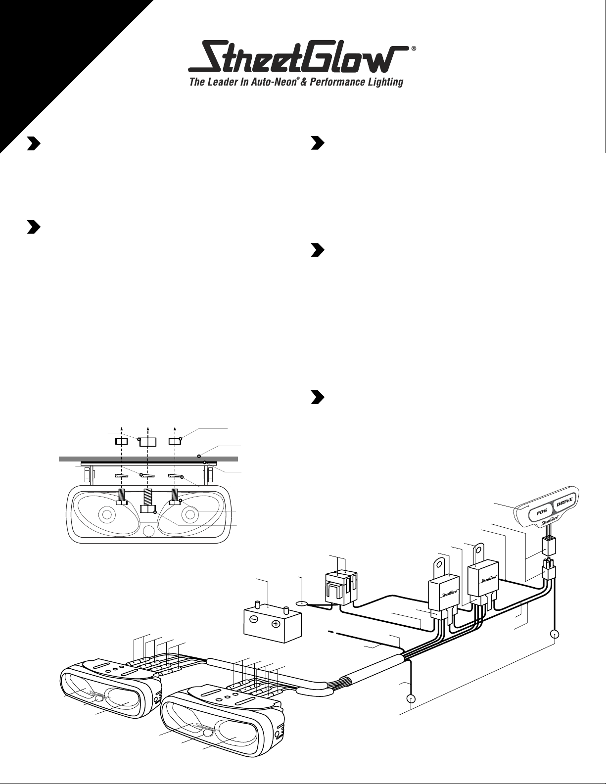
LAMP MOUNTING INSTALLATION
1. Select desired location of lamps, position lamp bracket using adhesive
tape (remove all dirt, wax, etc.)
2. Using 1/4” drill bit, drill mounting holes for lamp bracket and install bolts,
lock washer and nuts (Do not over tighten).(Figure 1)
3. Mount lamps on brackets, with fog lamps in the center most position. (Figure 2)
Make sure the vent hole is facing down on the lamp housing.
WIRE HARNESS INSTALLATION
1. CAUTION !! IN ORDER TO AVOID INJURIES AND SHORT CIRCUITS,
REMOVE THE (-) NEGATIVE TERMINAL FROM THE BATTERY
BEFORE ATTEMPTING ANY ELECTRICAL CONNECTIONS.
2. Mount relay to an accessible place in engine compartment using the
sheet metal screw provided.
3. Connect the wiring harness relay connector to mounted relay. (Figure 2)
4. Connect BLACK GND wire of harness to chassis ground of the vehicle
with ring terminal, then connect yellow wire from harness assembly to fit on
side marker lamp (+). (Figure 2)
5. Connect the BLUE, GREEN, YELLOW AND BLACK wires of harness
to the corresponding wires on the lamps.
6. Mount the switch in a convenient location on your dash.
7. Connect 4 pin male connector of harness to the switch’s female
connector, and then connect the RED wire from the 4 pin male
connector to vehicle’s low beam circuit. Connect BLACK wire
from 4 pin male connector to chassis ground. (Figure 2)
8. Reconnect the NEG (-) Te rminal on the battery and install the two 15amp.
fuses in harness for the lamps.
small nut
bumper
double face
adhesive tape
small lock washer
small bolt
large bolt
2 x15
Amp
B
a
t
t
e
r
y
(
+
)
T
e
B
a
t
t
e
r
k
rm
in
a
y
k
c
a
l
B
G
l
n
e
re
e
u
l
w
B
o
l
l
e
Y
Left Side
large lock
washer
Right Side
t
h
g
i
L
g
n
i
v
i
r
D
i
k
r
a
P
L
g
n
o
F
large nut
t
h
g
i
t
h
g
i
L
g
Figure 1
e
Y
t
h
g
i
L
g
o
F
k
r
a
P
w
o
l
l
n
e
e
u
l
re
B
G
c
a
l
B
t
h
g
i
L
g
n
i
t
h
g
i
L
g
n
vi
i
r
D
TESTING PROCEDURES
1. Start vehicle.
2. Tu rn the vehicle’s light to the “ON” position.
3. Tu rn on the power switch. (If the lamps turn on at this point,
there should be no problem with the connections) If the lamps do not
work, go back to steps (1 - 8) of the installation and check all the
processes over again.
4. With lights - ON - Aim lamps for proper alignment.A towel or heat
resistant gloves should be used as the lamps are extremely HOT.
5. Tu rn off vehicle.
CONTENTS
2 FOG / DRIVING / PARKING LIGHTS
2 POWER RELAYS
1 WIRE HARNESS
1 STREETGLOW LED ILLUMINATED 3 WAY POWER SWITCH
2 DOUBLE FACE ADHESIVE TAPE FOR MOUNTING BRACKETS
1 DOUBLE FACE ADHESIVE TAPE FOR SWITCH
1 QUICK SPLICE CONNECTOR
1 1/8” X 1/4” SCREW FOR RELAY
4 5/16” X 5/8” HEX BOLTS
21/4”X 5/8” HEX BOLTS
4 5/16” LOCK WASHER
21/4”LOCK WASHER
1INSTALLATION INSTRUCTIONS
CAUTION !
1. THE LAMP UNITS WILL BE EXTREMELY HOT WHEN THEY ARE ON,
AND IMMEDIATELY AFTER USE.
2. NEVER WASH THE CAR WHILE THE LAMPS ARE ON OR WHILE THEY ARE HOT.
3. KEEP THE WIRING HARNESS AWAY FROM MOVING PARTS OR EXCESSIVE HEAT
BY USING TIE STRAPS (NOT SUPPLIED).
4. IF THE FUSE BURNS OUT, INVESTIGATE THE CAUSE FIRST,
CORRECT IT, THEN REPLACE THE FUSE.
5. USE ONLY STREETGLOW H3, 55 WATT XENON WHITE®H.I.D.BULBS.
I
l
l
u
m
in
a
t
i
n
g
S
w
it
c
4
p
i
n
M
a
l
e
&
Fe
male
C
L
o
w
B
e
a
m
P
o
w
e
r
R
C
P
o
w
e
r
.
F
us
es
C
R
e
d
S
id
e
M
a
rk
e
r
L
a
m
Y
e
llo
n
i
-
g
lu
P
p
w
w
s
e
rn
a
h
g
in
ir
a
l
B
s
s
Cha
n
u
o
r
G
R
o
n
n
e
c
t
o
r
s
k
c
s
i
d
e
o
e
la
n
n
e
c
t
o
r
la
y
h
o
n
n
e
c
t
o
r
s
C
ir
c
u
it
y
R
e
d
n
e
e
r
G
e
u
l
B
Figure 2
 Loading...