


Pellet Boiler Varan 1.14., 1.20
Manual For Installation And Useage
Product Information


Varan 1.14, 1.20
Changes in models reserved.
Dimensions not binding!
3
Operation
When staring the boiler for the first time, it is possible that a noticeable odour development caused by heat-resitant coatings or
painting of single boiler parts may occur. During operation, these
coatings will cure and the odour will fade out.
Note that certain surfaces of the boiler will heat up during operation. If you come in contact with parts of the boiler, make sure
that they have cooled down properly or use suitable protective
gloves. Make sure that pieces of clothing and other heat-sensitive
materials do not come in contact with the boiler.
Because of the changes in temperature during heating up and
cooling down, boiler parts may give out expansium noises (mostly
knocking or crackling). The ocurrence of such sounds is no manufacturing or operation defect.
If you open the combustion chamber door during operation or
when the boiler is still warm, particles of ember or ash may fall to
the floor. Remove them with heat-restistant tools and protective
gloves. .
The installation of a hydraulic group is mandatory with boilers of this type series.
Operation Parameters
The user may only modify the operation parameters in the range
that is prescribed by this manual. The use of other settings than
those listed in this manual can cause malfunctions in the system.
The operating pressure must never exceed 2,5 bar. A boiler temperatur of above 90˚C is not allowed.
Because of possible risk of frost inside the aquiferous heating
pipes, it is recommended to not switch-off the boiler at outdoor
temperatures below 0°C if the boiler is the only heating element
in the system.
Spare Parts
To replace defective parts of the boiler, only use original STREBEL
spare parts.
Prescibed Fuel
The boiler is construdef only for the combustion of wood
pellets. Using any other fuel is prohibited. In any case, do
not use pieces of wood, paper, oil, plastic or other materials as fuel.
More information in chapter 3.
Safety Instructions
This User Manual
Every person who is intending to operate this boiler is obligated to read this manual carefully,
especially the safety instructions. This includes individuals which
are cleaning or maintaining the boiler.
Otherwise, the legal warranty expires.
Please keep and preserve this manual.
Usage Of This Boiler
The manufacturer is not responsible for damages resulting from
improper installation, maintainence or operation. In this case, the
user is liable and the legal warranty expires.
Respect local provisions and legal guidelines when setting up,
installing, operating and disposing the boiler. The boiler must be
installed by expert personnel. Do not make unauthorized modifica
-
tions on the boiler or its water and exhaust connections.
To transport the boiler, make sure that the transport aids and the
underground that the boiler has to traverse over are able to sustain its weight. The underground on which the boiler is stored or
installed on should also have the suitable load capacity.
So not expose the boiler to weather conditions. The installation
and storage is only authorized indoors (VDE 0100 part 200). Do
not cover the boiler or lean/place objects directly beside it. The
installation in wet spaces/humidors is not permitted. The boiler is
not protected against spray water.
The person responsible for installation and/or implementation
must inform the user about the correct operation and cleaning of
the boiler. Only use the boiler if it is installed correctly. Always
adhere to this user manual. Malfunctions are to be repaired as
soon as possible.
This boiler may only be used for the purposes it is intended and
was manufactured according to current safety requirements. Incorrect use may cause damage to the boiler or to other objects in
in close proximity. Accidents, injury or even death of the usermay
occur if the safety instructions are violated.
The operation of this appliance by children or individuals with
restricted perception or motoric abilities, each without accompaniment, is prohibited. Pay attention that children or pets do not
comke in direct contact with the boiler or climb it.
It is prohibited to place heavy objects on the boiler or stepping
onto it.
Safety Instructions

Varan 1.14, 1.20
Changes in models reserved.
Dimensions not binding!
4
Safety Instructions
Possible Risks
If the combustion chamber door or cleaning openings are left open
during operation, carbon monoxide is able to discharge from the
boiler. Do not leave them open longer than necessary. Insufficient
air supply during operation is lethal. It is prohibited to close the
openings of the boiler or the installation room that provide the
fresh air needed for operation.
This boiler has electric components which are live during operation, as well as movable parts on the inside. Under any circumstances do not stick a finger or other objects in the openings of the
boiler. There is a danger of electric shocks or burn injury, as well
as property damage.
In case water is leaking from the boiler, stop its operation immediately and have competent service personnel at the damage.
Minimum Distance Of Flammable Materials
Keep flammable materials and objects away from the boiler and
make sure that the insulation material below the boiler protects
the floor from harmful heat exposure. The minimum distance flammable objects have to be kept abway from the boiler is stringently
prescribed and is subject to regional directives. Ask your chimney
sweep for detail information.
In case the boiler is not installed in a seperate boiler room but in
the living space with an open flue, combustion air is taken from
the living space as well.
The minimum distance from the boiler and its exhaust pipe tomaterials with low or intermediate flammability is 100 mm. The
minimum distance from easily flammable objects is 200 mm. The
latter also counts for materials if their flammability is unknown.
Fresh Air Intake
Boilers need a suitable air supply to maintain combustion.
Open Flue: Under certain circumstances, if the fresh air is taken directly from the boiler room, an insufficient supply of oyxgen
needed for combustion may occur. This is especially prominent in
houses or flats with tightly sealed doors and windows. Operating
the boiler without constant supply of outside air can cause sevee
problems in operation. It is recommended to install an automatic
venting system in the builduing or use a balanced flue system.
Balanced Flue: The fresh air opening is connected with a sealed
pipe which takes air from the outside or a seperate room with
constant fresh air supply.
Keep the air supply pipe as short as pos-
sible. It is recommended to install the pipe with the capability to
be shut off (according to EnEV) to prevent humidity from entering
during longer operation pauses.
Avoid using combustion air from the flue. Because of the flue drau
-
ght, there is always negative pressure.
The simultaneous operation of artificial ventilation (e.g. cooking
hood) and the pellet boiler in the same room is prohibited. The air
suction may cause problems in boiler operation and discharge of
carbon monoxide.
Talk to your chimney sweep about regional prescriptions
regarding air supply.

Varan 1.14, 1.20
Changes in models reserved.
Dimensions not binding!
5
Contents
Boiler Features
1 Boiler Features
1.1 General Information
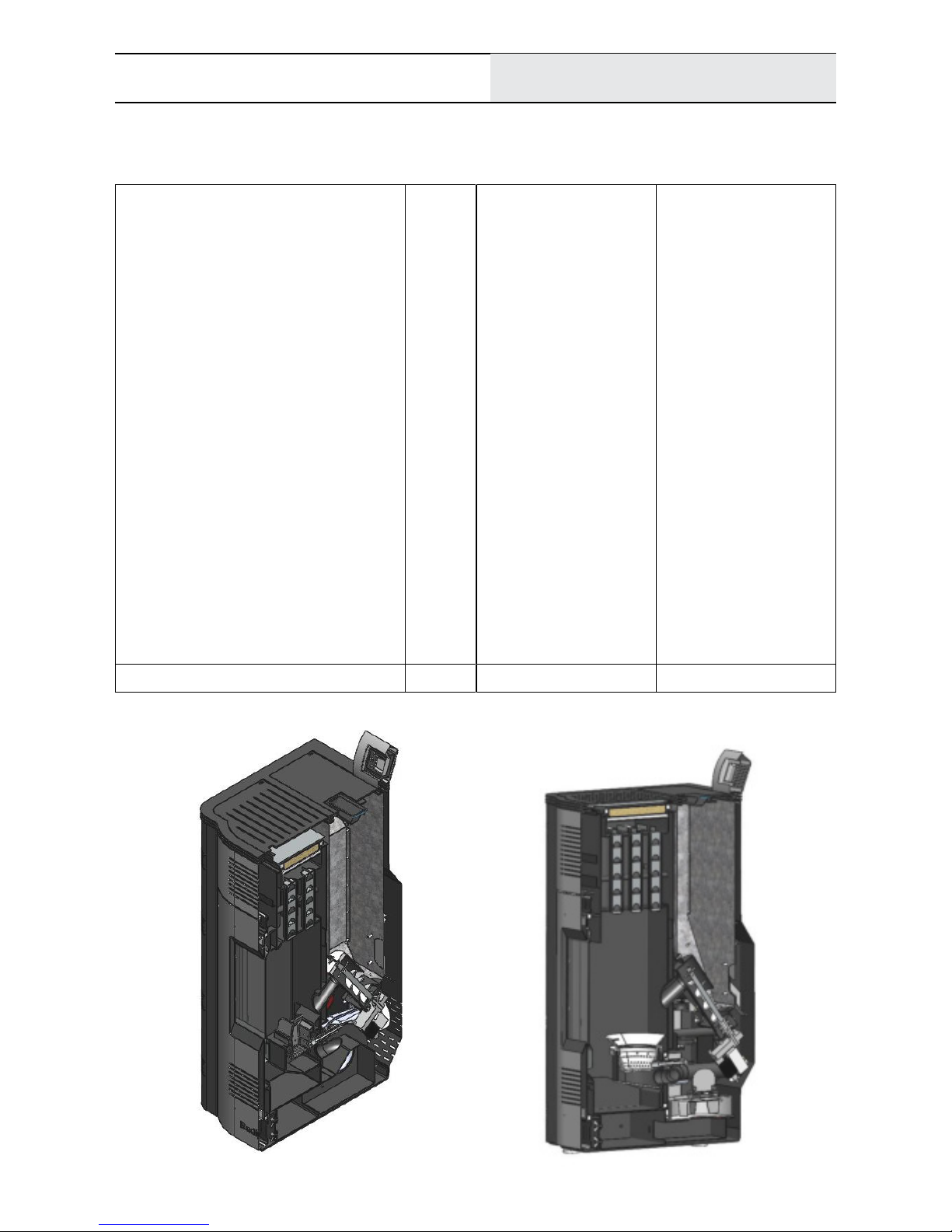
The STREBEL Varan 2.20 is a pellet boiler for aquiferous central heating systems with radiators and/or underfloor heating. It
is designed to be set up directly in the living space (without an
external boiler room neded). During operation, heat is transmitted
directly into the room vis the boiler surface as well as into the
heating system.
Components
The integrated pellet tank is filled by hand and holds 45 kg or 75
litres of wood pellets. The pellet discharge takes place via auger,
a silent, energy-saving reduction gear and a downpipe.
An expansion vessel (10 litres), an electronically controlled Wilo
HE circulator pump and a safety group are already installed in the
compact boiler construction. The controller has a daily, weekly and
weekend programme as well as three programmable performance
levels.
1 Boiler Features ............................................................................................................................... 5
2 Technical Data ................................................................................................................................ 6
3 Fuel ................................................................................................................................................. 8
4 Construction .................................................................................................................................. 9
5 Installation...................................................................................................................................... 12
6 Controller ........................................................................................................................................ 18
7 Operating Phases ........................................................................................................................... 26
8 Maintenance .................................................................................................................................. 28
9 Possible Malfunctions .................................................................................................................... 30
10 First Start-Up .................................................................................................................................. 32
11 Boiler Disposal ............................................................................................................................... 32
Varan 1.14, 1.20
6
Technical Data
2 Technical Data
Pellet Boiler
Rated heat output kW
Rated output into the heating system kW
Rated output directly from surface kW
Distance from floor to centre of exhaust connection mm
Exhaust connection mm
Flue draught Pa
Efficiency %
Pellet tank volume kg/Litres
Weight kg
Water volume Litres
Operating/testing pressure bar
Boielr temperature min./max. °C
Return temperature min. °C
Power supply
Connections flow/return Inch
Flue gas temperature (rated output, min. output) °C
Energy label (Range A++ to G)
Changes in models reserved. Dimensions not binding!
Varan 1.14 Varan 1.20
11.9 20
10.45 18.7
1.45 1.3
180 134
80 80
11 11
>91 >91
45/75 45/75
192 235
24 38
2.5/5 2.5/5
60/90 60/90
55 55
230 V /50 Hz 230 V /50 Hz
1“ 1“
135/90 135/90
A++ A++
Schematic section Varan 1.20
Schematic section Varan 1.14
Varan 1.14, 1.20
Changes in models reserved.
Dimensions not binding!
7
Technical Data
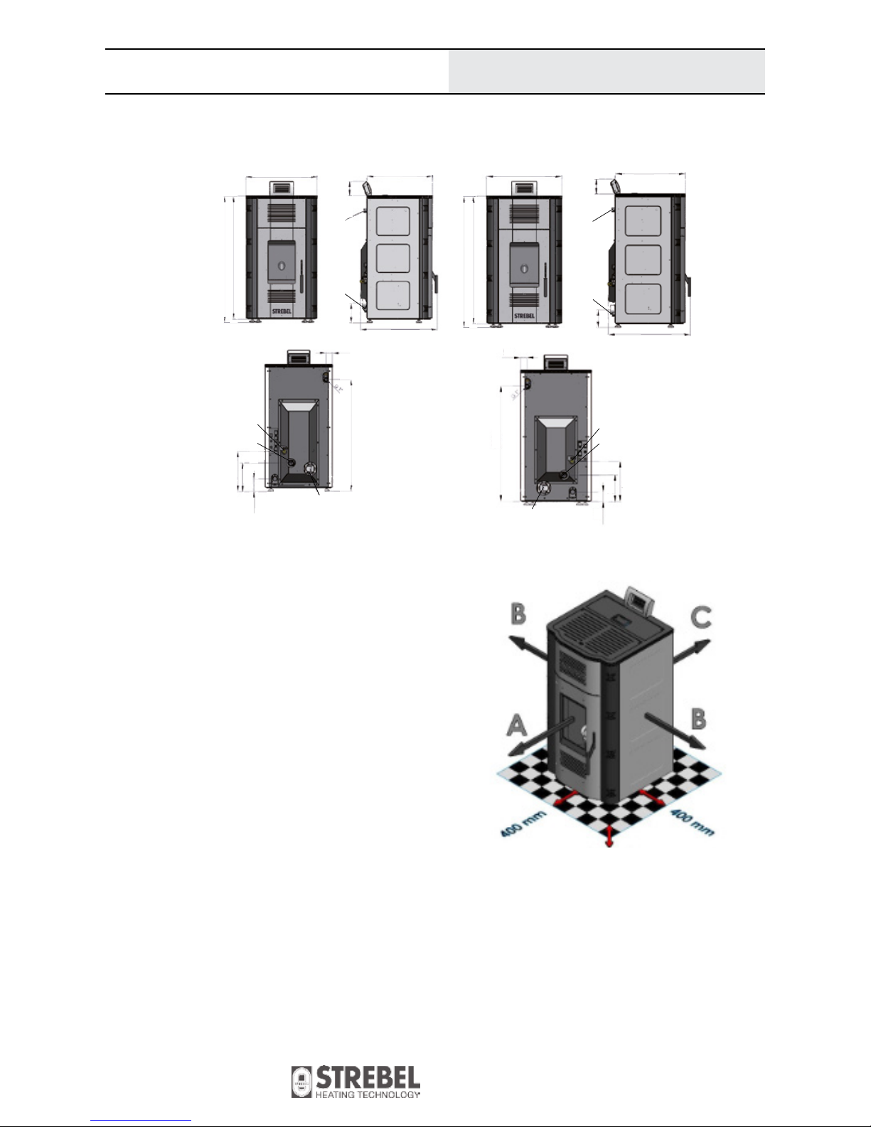
2.1 Dimensions (in mm)
mics, ceramic-based insulation etc.). Such plates have to be
larger than the floor area of teh boiler itself.
- Keep furniture and other objects at leat 1 metre away from
the boiler.
- The distance between the boiler and immobile, solid objects
(walls pillars etc) has to be at least 40 cm (measure B), 20 cm
from the backside (measure C) and 100 cm from the front
(measure A). These distances are necessary to allow cleaning
and maintenance of the boiler.
2.2 Recommended Space For Service And Maintenance
When placing the boiler prior to installation, make sure of the following:
- The boiler must be installed as close to the flue and fresh air
connections as possible.
- For the operation of the appliance, a power supply of 230 V
and 50 Hz is needed. Keep the connection line as short as
possible and avoid using extension cords.
- If possible, install the boiler in the largest, most central room
of the building.
- The boiler must not be installed in bedrooms or rooms that
are inseperatable from the beedroom througha door.
- Do not operate other boilers (for wood or pellets) inside the
room where the Varan boiler is installed to keep up the
necessary air supply.
- The installation room must have windows or doos that can
be opened for additional fresh air supply or there should be
at least an adjacent room connected to the installation room
trough a non-flammable pipe that is open at any given time
during operation. This adjacent room must have windows or
doors that can be opened to provide fresh air.
- In case the boiler is placed on flammable underground
(e.g. laminate, parquet, carpet), it must be insulated with
a plate consisting of non flammable material (steel, cera-
Der integrierte Pelletsbehälter befindet sich
im hinteren Teil des Kessels und ist über
eine Klappe an der Geräteoberseite zugäng-
lich. Der Behälter wird von Hand befüllt und
fasst 45 kg bzw. 75 Liter Pellets. Eine schräg
ansteigende Pellets-Zubringerschnecke mit
Getriebemotor transportiert den Brennstoff
zum Fallrohr, über das er in die Brennertasse
fällt. Diese Bauweise verhindert, dass Flam-
men aus dem Brennraum auf den Brennstoff
im Behälter übergreifen können.
Der Abgasventilator regelt die Verbrennung
und hält die Flamme mit einem kontinuierli-
chen Luftstrom konstant. Je nach Bedarf und
eingestellter Leistung variiert die Laufge-
schwindigkeit und der Pelletseintrag in den
Brennraum. Die automatische Zündung sorgt
jedes Mal für einen sicheren Betriebsstart.
Reinigung
Für eine unkomplizierte und schnelle Reini-
gung lässt sich die Brennerschale im abge-
kühlten Zustand mit einem Handgriff aus der
Ausnehmung im Brennraum herausnehmen.
Die Asche wird in einen feuerfesten Behäl-
ter ausgeklopft. Danach die Schale wieder
einsetzen.
Brennstoff
Als Brennstoff für alle Modelle eignen sich
handelsübliche Holzpellets (nach ISO 17225-
2:2014 Qualität A1, ENplus-A1, ÖNORM M
7134). Pellets in Form von Sackware (übli-
cherweise 15 kg/Sack) lassen sich gut sta-
peln und an einem trockenen Ort über viele
Jahre lagern.
Pellets – kleine Umrechnungstabelle
1 Kubikmeter Pellets wiegt ca. 650 kg.
1000 kg Pellets brauchen ca. 1,5 m³ Raum.
1 kg Pellets liefert ca. 5 kWh.
Der Heizwert von 1 kg Pellets entspricht
jenem von ca. 0,5 Liter Heizöl.
STREBEL Pellets erhalten Sie als Sackware
(15 kg) einzeln oder auf Palette. Abholung in
unserem Werk in Wr. Neustadt oder Haus-
zustellung zwischen Wien und Gloggnitz.
Falls wir Ihr Interesse geweckt haben, neh-
men Sie Kontakt zu uns auf. Sie erhalten
eine kostenlose und unverbindliche Beratung
durch unsere Außendienstmitarbeiter in der
jeweiligen Region – auf Wunsch auch vor
Ort.
Abmessungen und Anschlüsse
966
866
81
360
270
55
55
55
80
221
600 530
620
600
1050
1020
Rauchrohr
Rauchrohr
Rauchrohr
Frischluft
Frischluft
Füllhahn
Frischluft
800
740
785
241
356
100
Varan 1.14 Varan 1.20
Varan 2.20
126
126
VL VL
VL
RL
RL
RL
696
1130
1110
134
180
134
1265
1285
628
336
600
Füllhahn
Füllhahn
ÖNORM
M 7135
PELLE TS
Qualität A1
für alle gängigen
Pelletskessel
Exhaust connection
Exhaust connection
Return
Return
Filling valve
Filling valve
Flow
Flow
Fresh air
Fresh air
Varan 1.14, 1.20
Changes in models reserved.
Dimensions not binding!
8
Fuel
3 Fuel
3.1 Required Fuel Quality
The boiler is construdef only for the combustion of wood pellets. Using any other fuel is prohibited. In any case, do not use
pieces of wood, paper, oil, plastic or other materials as fuel.
Wood pellets are zylindrical and made from wood scraps without additives or chemical binders. The pellets must show standard simensions and a low moisture content.
For the best possible combustion use pellets with the quality A1 according to ISO 17225-2:2014, with the seal ENplus-A1 and ÖNORM.
These standards comprise requirements in pellet quality, test regulations, control of production and labelling.
Parameter Unit Quality A1
Length mm 3.15 – 40*
Diameter mm 6 (+/- 1)**
Chaloric value MJ/kg min. 16.5
Mechanical strength % (Mass) min. 97.5
Dust (<3,15 mm) % (Mass) max. 1
Bulk density kg/m
3
min. 600
Water content % (Mass) max. 10
Ash content % (Mass) max. 0.7
Cinder softening temperature °C min. 1200
Arsenic content mg/kg** max. 1
Led content mg/kg** max. 10
Cadmium content mg/kg** max. 0.5
Chloine content % (Mass)** max. 0.02
Chrome content mg/kg** max. 10
Copper content mg/kg** max. 10
Nickel content mg/kg** max. 10
Mercury content mg/kg** max. 0.1
Sulphur content % (Mass)** max. 0.03
Nitrogen content % (Mass)** max. 0.3
Zinc content mg/kg** max. 100
* Max. 1% of the pellets (regarding mass) may exceed a length of 40 mm. More than 45 mm are not permitted.
** in anhydrous condition
Varan 1.14, 1.20
Changes in models reserved.
Dimensions not binding!
9
Construction
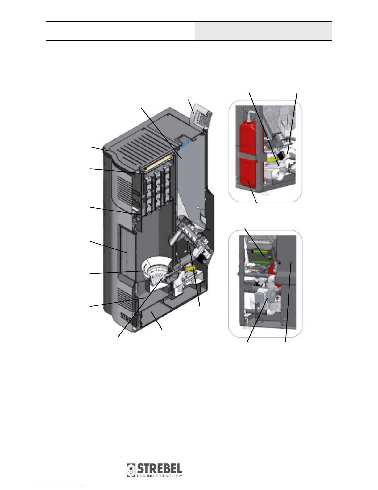
4. Construction
4.1 Boiler Main Parts
Heat exchanger
with turbolators
Cover
Cleaning opening
Pellet tank
Combustion
chamber
Ash tray
Door with
special glass
Pellet auger
Controller processor
Flue gas fan Gear motor
Pressure switch
Circulator
pump
Flue gas channel
Igniter
Controller
Expansion vessel (10 litres)
Varan 1.14, 1.20
Changes in models reserved.
Dimensions not binding!
10
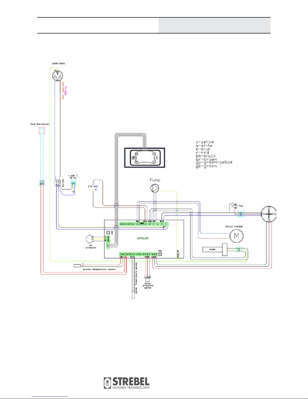
4.2 Electrical Scheme
Construction
The hatched lines are wires which the qualified personnel must connect to the controller during installation. Connectors of additional
appliances have to pass via two connectors on the boiler backside. The connectors are bi-pole or tri-pole. The tri-pole connector is used
to connect a room thermostat.
Only use battery powered room thermostats! On the thermostat itself, the connection with an NC (normal closed contact) is used.
Varan 1.14, 1.20
Changes in models reserved.
Dimensions not binding!
11
Construction
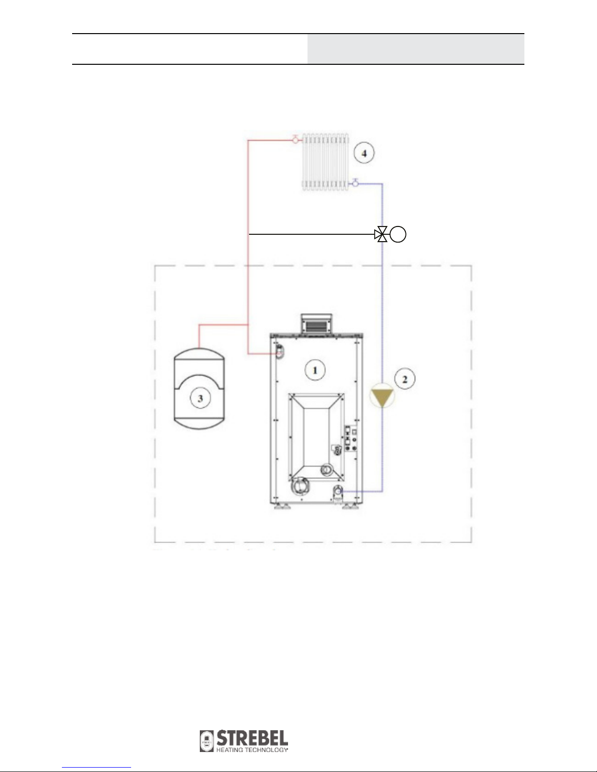
4.3 Hydraulic Scheme
Key:
1. Boiler
2. Circulator pump (integrated in boiler)
3. Expansion vessel 10 litres (integrated in boiler)
4. Radiators, underfloor heating system (via temperature limiter)
5. Thermal valve (min. 55°C)
Always make sure to comply with regional prescriptions when installing a boiler.
STREBEL does not take responsibility for damages caused by a faulty installation of the boiler.
th
5

Varan 1.14, 1.20
Changes in models reserved.
Dimensions not binding!
12
This safety element constantly measures the pressure inside the
heat exchanger and transmits the information to the controller.
In case the pressure sinks below 0,5 bar or exceeds 2,7 bar, the
boiler stops operation. The limit values are programmed into the
controller.
This component measures the draught in the exhaust channel and
transmits the data to the controller. In case the draught value sinks
below or exceeds the parameter, teh boiler stops operation and
shows an alert message.
NOTE: The flue draught may change due to cloggings or heavy
pollution of the flue or the boiler, or defective boiler sealings. Also,
bad weather conditions may influence the flue draught.
The controller is connected to an independent thermostat which is
used to limit the boiler temperature.
This safety thermostat interrupts the operation of the fan. The
temperature is limited to 95°C. This safety thermostat is located
below the main switch.
Installation
5 Installation
5.1 General Warnings
Mind regional prescriptions and legal guidelines during installation, operation and disposal of the boiler. The boiler must be installed by qualified personnel.
This boiler is designed to run in aquiferous central heating installations with an operating pressure of max. 2.5 bar an max. water
temperature of 90°C.
The combustion chamber door must remain closed during normal
heating operation.
All electrical components of the boiler need a power supply of 230
V. An improper connection can result in electrical shocks.
Prior to installation, check the boiler for visible damages.
5.2 Safety Devices
Make sure that the following components are always in function:
- safety valve, vent valve,
- electro-mechanic water pressure switch
- vacuum actuator
- boiler thermostat.
Safety valve vent valve
Water pressure switch
Vacuum actuator
Thermostat

Varan 1.14, 1.20
Changes in models reserved.
Dimensions not binding!
13
5.3 Flue Connection
When connecting the boiler with the flue, there are two stages
of montage:
- Montage of the flue pipes and air supply for combustion.
- Connection to the flue.
Montage of the flue pipes and air supply for combustion:
- The STREBEL Varan has an exhaust and an air supply
connection on its back side.
- Only use certified, stainless pipes for the flue connection.
The exhaust connection has a diameter of 80 mm. It is prohi bited to reduce the diameter in the following flue pipes.
- The flue gas pipe must not be used for multiple applianes at
once.
- Only use a maximum of two 90° angle pipe pieces. The
maximum length of a horizontal pipe distance is 2 metres.
- In case the pipes are near flammable materials or lead through
them, the pipes must be insulated.
Installation
For safety reasons, the circulator pump is connected to
the controller. In case the water temperature reaches
the critical value of 95°C, the fan ceases operation.
The pump continues running constantly and derives the excess
heat to the radiators, until the temperature is in normal range.
The heating system is to be filled slowly, allowing it to be vented
well. During filling of the installation, check if there are leaks in
the system.
- The pipes and connection elements usually show o-rings
made from silicone. If they do not have this kind of seal,
use fireproof sealing agent.
- The flue pipe must be detachable when necessary or have an
revision opening installed.
- In case the flue pipe does nor lead directly into the flue, but
vertically upwards, the installation of a condensate collector
is prescribed.
- The air supply from outside of the building for combustion
must be guaranteed. Use a pipe consisting of black or Inox
steel. The minimum diameter for this pipe is 50 mm.
- If it is not possible to take fresh air from the outdoors, the
intake must be carried out from an adjecent room with contant
fresh air ventilation. This fresh air connection must be
designed in a way that is is impossible to shut off (e.g. when
closing doors or windows)
Note: The safety valve of the current version is located not
in front of the boiler like in this picture, but on the boiler
backside.

Varan 1.14, 1.20
Changes in models reserved.
Dimensions not binding!
14
Situation 1 Chimney Connection Varan 1.14
Connection To The Flue
Montage Possibilities
- Situation 1: The boiler is connected to a standard chimney
(stone-walled or metal), which has a fundament and a whole
cross section of the fundament plate to the upper end point.
- Situation 2: The boiler is connected to a stainless steel flue
which is mounted to the facade.
Installation
Situation 1:
- The chimney uses ceramic or metal pipes of circular cross section of 130 mm diameter. The flue pipe must be insulated.
- If the chimney already exists and is of square cross-section,
then the minimum dimension of the intersection is
130x130 mm.
- It is not allowed to use one chimney for connecting multiple
boilers.
- It is not allowed to use the air vents like a chimney.
- The top of the chimney must be protected with a chimney
cap due for the impact of rain and winds.
Distance of chimney to cap is 200 mm.
- The chimney should come out above the roof according to
the recommendations in the image on page 17.
If other objects are near the chimney, take this into account
and increase the height of chimney.
- The chimney must have a connection to extract condensation
and an inspection door. The door should always be sealed
well during the operation.
Air supply connection Exhaust connection

Varan 1.14, 1.20
Changes in models reserved.
Dimensions not binding!
15
Installation
Air supply connection
Exhaust connection
Situation 1
Chimney connection Varan 1.20

Varan 1.14, 1.20
Changes in models reserved.
Dimensions not binding!
16
Installation
Situation 2:
- In this situation flue pipe must go at least 1.5 meters
vertically upwards in the very room where the boiler is
placed. Penetrate through the wall and connect the pipe
onto the chimney.
- The flue pipe must have a T-piece for condensation at the
outlet of the boiler and the possibility of dismantling for
cleaning.
WARNING: Failure to follow the rules during the execution
of flue and chimney can lead to malfunction of the boiler and
danger to objects and to human health. The most notable danger
is from the toxic gases (carbon monoxide) which are the products
combustion process.
Important: We recommend to perform a chimney evaluation
prior to installation.
1 Condensate collector
2 T-piece
3 Flue pipe
4 Knee 90° female-male fittings
5 Rosetta female-female fittings
6 Rosetta male-female fittings
7 Knie 90° male-male fittings
8 Wall brackets
9 Cover
Outdoor parts must
be insulated

Varan 1.14, 1.20
Changes in models reserved.
Dimensions not binding!
17
Installation
0 to 1,5 m 1,5 to 3 m over 3 m

Varan 1.14, 1.20
Changes in models reserved.
Dimensions not binding!
18
6 Controller
The operating parameters the user has access to are visible on the screen. Additional parameters which influence boiler operation are
reserved for qualified personnel ans must not be changed without reasons.
6.1 Controller Display
Controller
Controller panel with buttons and screen
Button Functions Description
P2 (ON/OFF) Activating/Deactivating,
reset alarm
Hold button (about 3 sec.) until a sound is audible.
P4 (
^
)
P6 (v )
Sub menu selection,
parameter selection
change of parameter
Move through the menu.
Change the values of parameters (increase/decrease).
P1 (ESC) Leave, cancel Leave current menu.
P3 (SET) Confirm Confirm/Access the current selection. Save changes.
P5 (#) Time programme Activating/Deactivating of the individual time programmes.
Summer/Winter mode
Time programme
Date/Time
Current operation phase
Service display
Alarm
Preset temperatureCurrent temperatureActivated parts
Pellet auger
Power level and operation mode (auto/man)
P1 P4
P2 P5
P3 P6

Varan 1.14, 1.20
Changes in models reserved.
Dimensions not binding!
19
Scheme of the controller panel with all possible activated parts, dots L1–L12
Controller
Function Description Part
Electrical igniter Dot visible: The igniter is active L1
Pellet auger Dot visible: The auger motor is active. The auger transports pellets into the combus-
tion chamber.
L2
Circulator pump Dot visible: The circulator pump is running. L3
Three way switch valve Dot visible: The three way switch valve (mixing valve) is active (only with domestic
hot water module)
L4
Output V2 Not used. L5
Fanr Not used. L6
Exit Aux2 Not used. L7
Not used. Not used. L8
Not used. Not used. L9
Filling level Not used. L10
Room thermostat Dot visible: Preset room temperature reached (contact open) L11
Flow meter Not used. L12
Hold button P6 to see this display of current operating values.
[°C]
[°C]
[°C]
(optional room temperatur sensor) [°C]
(water) [mbar]
[cm/s]
[s]

Varan 1.14, 1.20
Changes in models reserved.
Dimensions not binding!
20
Controller
6.2 Aufrufen des Menüs
Hold button P3 (SET) to open the menu. Use the arrow keys to select a menu item and confirm the choice with P3 (SET).
Menu item Description
Combustion Power Modification of the combustion programmes: AUTO, P1, P2 oder P3
Heating Power Not used.
Boiler Thermostat Set the desired boiler temperature.
Buffer Thermostat Set the desired buffer or domestic hot water tank temperature.
Not visible if P26 = 2, 3 or 4.
Room Thermostat Set the desired room temperature (if a room sensor is present).
Only visible if A19 = 1.
Chrono Modality Select programme: Day, week, weekend, deactivated
Chrono Program Adjust 3 switching cycles per day.
Time and Date Set time and date.
Remote Control Not used.
Calibration Set auger run time and fan RPM
Load Select this menu item to transport a starting load of pellets into the combustion
chamber (after pellet tank has been emtied completely. After selection, the auger
will run continously until a manual stop.
Summer-Winter Select between winter or summer mode.
Summer mode only provides domestic hot water.
Language Select the language shown on the controller menu.
Keyboard Menu Set contrast and min. backlighting.
System Menu Allows settings reserved for qualified personnel.
6.3 Menu Use
- To activate the menu, press P3 (SET).
- The display will show a list of menu items. Use the buttons
P4 (^) and P6 (v) and select – for example – ‚Combustion
Power‘.
- Confirm the selection with P3 (SET). It is now possible to
change the setting..
- The now visible screen (see scheme on the right side)
allows to change the setting using the buttons P4 (^) and
P6 (v); switching between Auto, 1, 2, 3.
- Confirm and safe your selection with P3 (SET).
- To return to the main screen, press P1 (ESC).
- If the controller did not successfully apply the new setting, the
display will read ‚Transmission not successful‘.
In this case, repeat the previous steps.
Parameter
Current setting

Varan 1.14, 1.20
Changes in models reserved.
Dimensions not binding!
21
6.9.1 ‚Modality‘ sub menu
- Choose between ‚Modality‘ and ‚Program‘ and confirm the
selection with P3 (SET).
- ‚Modality‘ lets you choos between:
‚Daily‘, ‚Weekly‘, ‚Weekend‘ and ‚Disable‘.
- Use P4 (^) and P6 (v) to select the desired menu item and
confirm the selection with P3 (SET).
6.9.2 ‚Program‘ sub menu
To programme the ON/OFF heating cycles, choose the item
‚Program‘ and confirm the selection with P3 (SET).
- Use P4 (^) and P6 (v) to select the time value. Confirm the
selection with P3 (SET) and the cursor moves to the next
value. Use P1 (ESC) to return to the previous value if necessary.
The three programmes are saved seperately. For example – making changes in the ‚Daily‘ programme will not affect any other
programming.
Important: To start operation with the programmed heating cycles, activate them using P5 (#). An active programme is marked
with a ‚V‘.
To deactivate an active programme, select it with the cursor (P4
(^) and P6 (v)) and press P5 (#) again.
Programming Over Midnight
For example, if a heating cycle is supposed to last from 6
pm/18:00 to 5 am/05:00, apply the following steps:
- Set the desired time on which the boiler should start heating
operation (e.g. ‚ON‘ to 18:00). Now, for the same day, set the
operation at 23:59 to ‚OFF‘.
- Now open the programming for teh following day and set the
operation at 00:00 to ‚ON‘. On the same day set the time at
which the boiler should cease operation.
Controller
6.4 Change Combustion Power
Parameter Description
3
Operation with power level 3
2
Operation with power level 2
1
Operation with power level 1
Auto
Operation starts with ‚level 3‘ and modulated
after reaching the control temperature
6.6 Boiler Temperature
Allows to set the temperature between a maximum and a minimum value (parameters Th26 and Th27).
6.7 Buffer Temperature
This sub menu is only visible if a tank probe is connected and
parameter P26 = 2,3,4.
6.8 Room Thermostat
Only visible if A19 = 1.
6.9 Chrono
(only use this option AFTER SETTING THE CORRECT TIME
AND DATE!)
Coose between the options ‚Modality‘ and ‚Program‘.
The ‚Modality‘ option is used to select the time programmes:
- „Daily“: seperate programming of every weekday (monday,
tuesday, wednesday, ... sunday);
- „Weekly“: from monday to sunday,
- or „Week-end“: from monday to friday and saturtay to
sunday seperately,
Completely disable the time programmes with the item ‚Chrono
(Disable)‘. The item ‚Program‘ allows to set the switching cycles.

Varan 1.14, 1.20
Changes in models reserved.
Dimensions not binding!
22
Controller
Examples for possible programming in the ‚Program‘ sub menu
6.10 Time And Date
Choose the current time resp. the date with P4 (^) and P6 (v) and
confirm yourcelection with P3 (SET).
Use P1 (ESC) to leave this setting.
6.11 Remote Control
Activate or deactive the connection with the
remote control.
8.2.8 Combustion Recipe Menu
Menu to select the Combustion Recipe. The maximum value is the number of recipes visible to the user. This
value can be set in System Menu Default Settings (parameter P04). If the parameter P04 = 1 the Menu
isn’t visible.
8.2.9 Time and Date Menu
This Menu allows to set time and date. Push the button P4 and P6 to select hours, minutes, year, month
and day. Push P3 to enter editing, P4 and P6 button to change the value. Push P3 to save and P1 to exit.
8.2.10 Remote Control Menu
This Menu allows to enable or disable the Remote Control SYTX.
Time and Date
Remote Control_______
Calibration
Load
Language
Remote Control
Enable
Disable
8.2.8 Combustion Recipe Menu
Menu to select the Combustion Recipe. The maximum value is the number of recipes visible to the user. This
value can be set in System Menu Default Settings (parameter P04). If the parameter P04 = 1 the Menu
isn’t visible.
8.2.9 Time and Date Menu
This Menu allows to set time and date. Push the button P4 and P6 to select hours, minutes, year, month
and day. Push P3 to enter editing, P4 and P6 button to change the value. Push P3 to save and P1 to exit.
8.2.10 Remote Control Menu
This Menu allows to enable or disable the Remote Control SYTX.
8.2.11 Calibration Menu
This Menu allows to modify the Combustion Fan’s speed and the Auger’s work time set by factory. It has two
Submenu.
Time and Date
Remote Control
Calibration _____
Load
Language
Auger Calibration
Fan Calibration
Time and Date
Remote Control_______
Calibration
Load
Language
Remote Control
Enable
Disable
6.12 Calivration
Set the running time of the auger and the RPM of the
fan. Coose from 10 calibration levels (the setting ex
factory is ‚0‘). Increasing or decreasing the value by
‚1‘ relates to an increase or decrease of 1%. This relative percentage can be adjusted (‚Calibration Step‘
in the system menu). The calibration effect is only
active in operating mode and in pellet modulation.

Varan 1.14, 1.20
Changes in models reserved.
Dimensions not binding!
23
Modelländerungen vorbehalten.
Maße unverbindlich!
6.13 Load
This item allows the manual activation of the pellet
auger. To activate the auger, select ‚ON‘ usingt P4 (^)
resp. P6 (v) and confirm your selection with P3 (SET).
To stop it, select ‚OFF‘ and confirm.
600 seconds after manual activation, the auger will
automatically stop.
The boiler must not be in operating mode during load phase!
Controller
8.2.8 Combustion Recipe Menu
8.2.9 Time and Date Menu
8.2.10 Remote Control Menu
8.2.11 Calibration Menu
8.2.12 Load Menu
Time and Date
Remote Control
Calibration _____
Load
Language
Auger Calibration
Fan Calibration
Time and Date
Remote Control_______
Calibration
Load
Language
Remote Control
Enable
Disable
Time and Date
Remote Control
Calibration
Load __________
Language
Load
ON
OFF________________
6.14 Summer-Winter
In Winter mode, the boiler will produce heating water as well as
domestic hot water (if the optional DHW module is attached). In
Sommer mode, it will only produce domestic hot water (if the optional DHW module is attached). If the Winter mode is active, the
display will show
8.2.13 Summer - Winter Menu
. In Summer mode, the symbol
is visible.
6.15 Language
Set the desired language of the display menu. Use
P4 (^) resp. P6 (v) to select a language and confirm
the selection with P3 (SET).
6.16 Keyboard Menu
Set the desired display contrast and the minimum
display backlight. Use P4 (^) resp. P6 (v) to select a
language and confirm the selection with P3 (SET).
8.2.13 Summer - Winter Menu
Menu to modify the plumbing plant functioning according to the season. On display appears one of these
symbols: , .
8.2.14 Language Menu
This Menu allows to change the language of LCD panel.
Time and Date
Remote Control
Calibration
Load
Language____________
Español
Française
Deutsch
English
Italiano______________
8.2.13 Summer - Winter Menu
Menu to modify the plumbing plant functioning according to the season. On display appears one of these
symbols: , .
8.2.14 Language Menu
This Menu allows to change the language of LCD panel.
8.3 Keyboard Menu
Menu to set the contrast and light of LCD panel.
Keyboard Menu_______
System Menu
Set Contrast
Set Minimum Light
Time and Date
Remote Control
Calibration
Load
Language____________
Español
Française
Deutsch
English
Italiano______________
8.2.13 Summer - Winter Menu
Menu to modify the plumbing plant functioning according to the season. On display appears one of these
symbols: , .
8.2.14 Language Menu
This Menu allows to change the language of LCD panel.
8.3 Keyboard Menu
Menu to set the contrast and light of LCD panel.
8.3.1 Set Contrast
This Menu allows to set the display contrast.
Set Contrast _____
Set Minimum Light
Set Contrast _____
+
15
-
Keyboard Menu_______
System Menu
Set Contrast
Set Minimum Light
Time and Date
Remote Control
Calibration
Load
Language____________
Español
Française
Deutsch
English
Italiano______________
8.2.13 Summer - Winter Menu
Menu to modify the plumbing plant functioning according to the season. On display appears one of these
symbols: , .
8.2.14 Language Menu
This Menu allows to change the language of LCD panel.
8.3 Keyboard Menu
Menu to set the contrast and light of LCD panel.
8.3.1 Set Contrast
This Menu allows to set the display contrast.
Push the buttons P4 and P6 to increase or decrease the contrast; P3 to save and exit, P1 to exit without
save.
8.3.2 Set Minimum Light
This Menu allows to set the display light when you don’t push any button.
Set Contrast
Set Minimum Light
Set Minimum Light
+
9 5
-
Set Contrast _____
Set Minimum Light
Set Contrast _____
+
15
-
Keyboard Menu_______
System Menu
Set Contrast
Set Minimum Light
Time and Date
Remote Control
Calibration
Load
Language____________
Español
Française
Deutsch
English
Italiano______________

Varan 1.14, 1.20
Changes in models reserved.
Dimensions not binding!
24
6.17 System Menu
This menu allows settings reserved for qualified personnel. Because of this, the menu is keyword protected.
Ex factory, the keyword is 2111.
To enter the keyword, confirm the selection ‚System Menu‘ with P3 (SET). Now it is possible to use P4 (^) and P6 (v) to increase or decrease
the displayed digit. Confirm the desired digit with P3 (SET). After that, the cursor moves to the next position until all 4 digits are filled in.
After the fourt digit is confirmed with P3 (SET) and the keyword is correct, the system menu will open.
Important: Changes in the system menu can cause malfuntions or damages to the boiler and the system!
6.18 operation Parameters
Pellet Auger
Parameter Recommended Description
C01 0.5 Ignition
C02 0.8 – 1.0 Stabilisation
C03 0.8 Power level 1
C04 1.6 Power level 2
C05 1.8 – 2.0 Power level 3
Boiler Fan (RPM)
Parameter Recommended Description
U01 1250 – 1400 Ignition
U02 1600 Stabilisation
U03 1550 Power level 1
U04 1600 Power level 2
U05 1650 – 1700 Power level 3
P23 1700 Burn out
Time Programme
Parameter Recommended Description Additional
T02 40 Igniter preheat time
T03 40 – 50 Auger r un time prior to ignition (for pellet
starting load)
There have to be enough pellets in front of the
igniter hole!
T04 450 Timespan between start and normal ope-
ration
T06 250 Stabilisation time Durin this time span, the boiler temperature
has to rise 7°C.
Controller
Keyboard Menu
System Menu _____
PASSWORD?________
- - - -
Modelländerungen vorbehalten.
Maße unverbindlich!

Varan 1.14, 1.20
Changes in models reserved.
Dimensions not binding!
25
Thermostat Menu
Parameter Recommended Description
Th01 55 – 65 The boiler switches off if the flue gas temperature sinks below the set value.
Th02 45 – 50 The ignition switches of when the flue gas temperature reaches the set point.
TH06 46 – 51 A the set flue gas temperature, the boiler switches from ignition phase to stabilisation phase.
Th19 50 The circulator pump starts running at the set temperature.
Ih19 2 Pump hysteresis
Th28 55 – 65 The boiler switches to standby mode if the flue gas temperature sinks below the set point.
Funktion Menu
Parameter Parameter Description
A01 0 The boiler switches to burnout at this temperature (room thermostat).
1 The boiler starts modulation at this temperature (room thermostat).
2 The boiler switches to standby at this temperature (room thermostat).
3 The pump is blocked at this temperature (room thermostat).
Forced switch on, wehen the set value in Th21 is exceeded.
A06 0 In modulation phase, der boiler runs with ‚P1‘
1 In modulation phase, der boiler runs with individually programmable parameters U11 and C11
Differencial Temperature Menu
Parameter Ex Factory Description
D01 7 Difference for stabilising
54°C (restart) – 60°C (preset temperature) – 66°C (standby):
results in hysteresis of +/- 6°C
D08 6 Difference for modulation
55°C (modulation start) – 60°C (preset temperature) – 66°C (standby):
Furter Important Parameters
Parameter Ex Factory Description
A24 0 Vacuum actuator
Controller

Varan 1.14, 1.20
Changes in models reserved.
Dimensions not binding!
26
7 Operating Phases
7.1 Start
7.1.1 Filling Tank With Pellets
Open the lid of the pellet tank on the top rear of the boiler and fill it with pellets. Only fill it to a level where the lid can still be closed
tightly.
7.1.2 Switch-on
Press the main switch on the boiler backside to switch on the boiler.
Make sure it is conected to the power supply.
The pellet tank lid is open
Operating Phases
Main switch
Backside

Varan 1.14, 1.20
Changes in models reserved.
Dimensions not binding!
27
7.2 Switching Off
To switch off the boiler, hold P2 (ON/OFF) for 2 to 3 seconds until
a conformation sound is audible. The boiler is now switched off.
Operating Phases
7.1.3 Starting Pellet Load
Activate the pellet dosing system for loading fuel into the combustion plate. This procedure can only be activated if the controller
display shows ‚OFF‘ on the main screen.
- Press P3 (SET);
- The display will read a list. Use the buttons P4 (^) and P6 (v) to select ‚Load‘.
- Confirm the selection with P3 (SET).
- Use P4 (^) resp. P6 (v) to select ‚ON‘ and confirm with P3 (SET).
- After pressing the button, the pellet auger starts running. Let it run until the first pellets fall into the combustion plate (visually
inspect through the inner combustion chamber door.)
- To stop this procedure, select ‚OFF‘ and confirm the selection.
- Press 1 (ESC) to leave the sub menu.
7.1.4 Starting Combustion
Hold P2 (ON/OFF) for 2 to 3 seconds until a conformation sound is
audible. The display will now read ‚Ignition‘. The boiler is now in
operation.
When using standard pellets and if the air-flue-installation has
been carried out correctly, the combustion process starts after 5
to 10 minutes.
When starting up a new Varan boiler, there may be an increased
amount of smoke and combustion odour. This occurs because of
coatings which protect the boiler against corrosion. After several
hours of operation, the coating is burned out and stops emitting
odours.

Varan 1.14, 1.20
Changes in models reserved.
Dimensions not binding!
28
8 Maintenance
8.2 Intervals Of Cleaning And Mainenance
The regular cleaning and maintenance works are very important
for a problem-free operation and guarantee a long boiler lifetime.
The timespan between the periodical maintenance depends on
pellet quality and power level of the boiler. On the combustion
chamber walls and the heat exchanger tubes, soot and tar will
form over time. Because of this, these parts have to be cleaned
mechanically.
Prior to starting the cleaning work, switch off the boiler on the
controller panel and on the main switch.
8.3 Daily Cleaning
During normal boiler runtime, ash is piling up inside the combustion chamber. To ensure a problem-free operation, the combustion
chamber should be cleaned out from ash every day. At standard
combustion parameters, the boiler will produce 1 kg of ash from
100 kg of pellets.
8.4 Every 3 To 4 Days
See images on the following page. Two times a week, thoroughly
clean out the burner plate. Scrape any coating off the combustion
chamber walls using a proper cleaning tool. A combustion chamber that is cree from soot coatings has the advantage of a better
heat transmission and therefore better efficiency. Approximately,
a coating thickness of 1 mm will reduce boiler efficiency by 5%.
8.5 Every 2 Weeks
Open the cleaning cover on the front top side of the boiler. Take
out the turbulator spirals and remove deposits from the sorals and
the heat exchanger tubes. The residues will fall down into the
combustion chamber where they can be cleaned out along with
the ashes. Use the revision openings on the flue pipe to clean out
gross contaminations.
8.6 Cleaning And Maintenance Trough Qualified Personnel
Adhere to locar prescriptions and legal guidelines when it comes
to periodical, professional cleaning and maintenance of the boiler
and the flue system. A yearly cleaning carried out by our customer
service is recommended.
When cleaning the combustion chamber with a
vacuum cleaner, the ash has to be cooled down
completely. Otherwise there is a risk of fire.
When taking the burner plate out of the combustion
chamber for cleaning, there is a risk of burn injuries
if handled improperly. Shortly after deactivating the
boiler, the combustion chmaber and ashes are still hot. Wait a
proper amount of time for the boiler parts have cooled down so
they may be touched safely. There is also a risk of burn injury
when cleaning the heat exchanger tubes, because they will heat
up to 200°C in operation.
Maintenance
During all cleaning work, there is a risk of suffoca tion (from carbon monoxide) if the boiler is still in
operation and the doors are opened. Do not leave
the boiler doors and lids open longer than necessary.
The amount of ash in the combustion chamber is related to the
pellet quality. High quality, dry pellets produce less ask andless
dust inside the pellet tank.
To prolong the lifetime of the igniter, regularily clean the air deduction and de igniter itself.
At the end of the heating season, the boiler have to be cleaned
thoroughly to prolong its lifetime and keep top efficiency. Close all
boiler doors and openings to minimise moisture build-up.
8.1 Special Instructions

Varan 1.14, 1.20
Combustion plate
Varan 1.14
Varan 1.20
Ash plate with wing nuts
Ash plate with wing nuts
Removable Parts When Cleaning
Maintenance
29

Varan 1.14, 1.20
Changes in models reserved.
Dimensions not binding!
30
9 Possible Malfunctions
All possible malfuntions in the operation of this device can be divided into two major groups.
Gruppe I: Error during the initial start of the boiler or the first start
after a short deactivation period.
Gruppe II: The boiler switches off during run mode. After reaching set temperatures and a forced pause, the boiler will not
start again without manual reset.
9.1 Group I
Adhere to the installation guidelines in the ‚Montage‘ part – especially the flue system (diameter, number of bends, sealing, ...),
as well as the chimney (diameter, height, sealing of revision openings, pullution etc.).
The most common error message of this group is „E12“. In case
of insufficient flame formation after ignition and if the flue gas
temperature failes to rise, the igniter will be displayed as active,
but the boielr will switch to extingushing phase. If this happens,
check the following:
- Bad pellet quality or wet pellets.
Solution: only use, dry, high quality pellets.
Combustion air temperature is too low (below 0°C).
Solution: set a longer ignition time t02 to 30 – 40
seconds.
- Power supply voltage is low (much below 230 V);
the igniter output is insufficient.
Solution: set a longer ignition time t02 to 30 – 40
seconds. If this measure is unsuccessful, install an AC
adapter that provides 230 V.
- Pellet starting load insufficient, no flame formation.
Solution: Have qualified personnel check for mechanical
problems on the auger or the motor.
- Flame formation is successful, but the boiler remains
in stabilisation phase and does not enter run mode.
Solution: The boiler needs more fuel in the combustion
chamber. Set a longer timespan in parameter t03 – increase
it step by step for a few seconds each. Please also mind the
following reference.
- There is flame formation after the timespan set in t03,
but the boiler does not switch to stabilisation phase
t04. The flame is getting weaker and the flue gas tem perature is sinking. The boiler switches to extingu ishing phase.
Solution: Decrease the timespan set in parameter t04
(stabilisation phase) it step by step for a few seconds each.
Please also mind the previous reference.
The boiler controller may display the following messages resulting from a malfuntion.
Er01 Error – High voltage (even when boiler is not in operation)
Er02 Error – High voltage (only when fan is in operation)
Er03 Error – Low flue gas temperature; boiler ceases operation
Er04 Error – High boiler temperature; boiler ceases operation
Er05 Error – High flue gas temperature; boiler ceases operation
Er07 Error – Signal error between encoder and controller
Er08 Error – Encoder encouters problems with counter
Er09 Error – Low water pressure
Er10 Error – High water pressure
Er11 Error – Wrong time-setting
Er12 Error – Ignition failed
Er15 Error – Low power supply voltage
Er17 Error – Error in vacuum actuator
Er18 Error – Low pellet level (not used)
Er39 Error – Vacuum actuator defective
Er41 Error – Minumum negative pressure could not be reached
Er42 Error – Negative pressure to high
Possible Malfunctions

Varan 1.14, 1.20
Changes in models reserved.
Dimensions not binding!
31
- The boiler is connected to a room thermostat, but does
not switch to ignition mode
Solution: Check the current room temperature and compare
it to the related preset temperature on the boiler. Make sure
that the heating cycle is currently in operation. Test the room
thermostat for possible malfunction.
9.2 Group II
The most common error message of this group is Er03.
- The boiler has already been in run mode but ceased
operation. During a new heating demand (from boiler
or room thermostat), it will not start operation again.
the combustion chamber is filled with unburned pel lets.
Solution: Check the values in the parameters A26, Th28 and
Th06. They may have been altered.
The parameter A26 must be set to ‚1‘.
The parameter Th06 must be between ‚60‘ to ‚65,
and parameter Th28 must be at least 2°C lower than Th06.
Adjust the parameters, clean the combustion chamber and
restart the boiler.
- The boiler has already been in run mode, but unburnt
pellets are piling up in teh combustion chamber. The
flames are getting smaller and are extinguished.
Solution: Increase exhaust the fan RMP in all phases using
the calibration menu.
- The boiler is operating, but is stops unexpectetly and
starts modulationg. After that, a safety switch-off
occurs. (Extingishing) (Error Er05).
Solution: The flue gas temperature is too high – possibly
resulting from a polluted boiler, too much draught, high fan
power, too many pellets in the combustion chamber, bad
pellet quality, etc. This problem can be solved usually by
adjusting one of the parameters for the transmission to
modulation or the safety switch-off (resulting from high flue
gas temperature): Parameters Th07, Th08.
Possible Malfunctions

Varan 1.14, 1.20
Changes in models reserved.
Dimensions not binding!
32
First Start-Up
Boiler Desposal
10 First Start-Up
The first start-up of this boilermay only be carried out by a professional of the company STREBEL or an experienced installer. If the
start-up is not carried out correctly, the boiler and the system can
be damaged, destroyed or injury and material damage can occur.
10.1 Precautions for the fisr start-up
1.) Disconnect boiler from power supply.
2.) Check if the red main switch on the boiler side is activated.
3.) Check if the following parts are installed professionally and
working.
- All mechanical parts of the boiler,
- burner and chamotte bricks,
- fan,
- circuit pump,
- safety valve.
4.) Check of all electrical connections:
- Correct installation of all electric components (gear motor,
fan, controller, display),
- Protection of unused connections,
- ground,
- power supply.
11 Boiler Disposal
11.1 Removal
The boiler removal must be carried out by qualified technicians.
Otherwise, injury or material damage can occur.
Procedure of the removal
1.) Stop boiler operation.
2.) Wait until the pellets in the burner room are burnt up and the
boiler is cooled down.
3.) Disconnect the boiler from power supply.
4.) Disconnect the boiler from the rest of the heating installation
with a turncock and drain the water from the boiler.
5.) Remove pellet silo.
6.) Remove boiler shell.
7.) Remove mineral wool insulation from the boiler body.
11.2 Disposal
The steel parts of the boiler are delivered to a recycling centre:
- Boiler body,
- boiler shell,
- pellet silo,
- screw,
- gear motor,
- burner.
The electrical parts as well as glas parts, mineral wool and plastic
parts are seperately delivered to the recycling centre.
The boiler parts must not be disposed in the domestic waste bin.

Varan 1.14, 1.20
Changes in models reserved.
Dimensions not binding!
33
Space For Notes

Varan 1.14, 1.20
34
Space For Notes

Varan 1.14, 1.20
Changes in models reserved.
Dimensions not binding!
Varan 1.14, 1.20
35
Space For Notes

2700 Wiener Neustadt, Wiener Strase 118, AUSTRIA
Telefon +43 (0)2622 235 55-0
Fax +43 (0)2622 253 46
verkauf@strebel.at
www.strebel.at
Strebelwerk GmbH
NAK, 0217
 Loading...