

Page 1
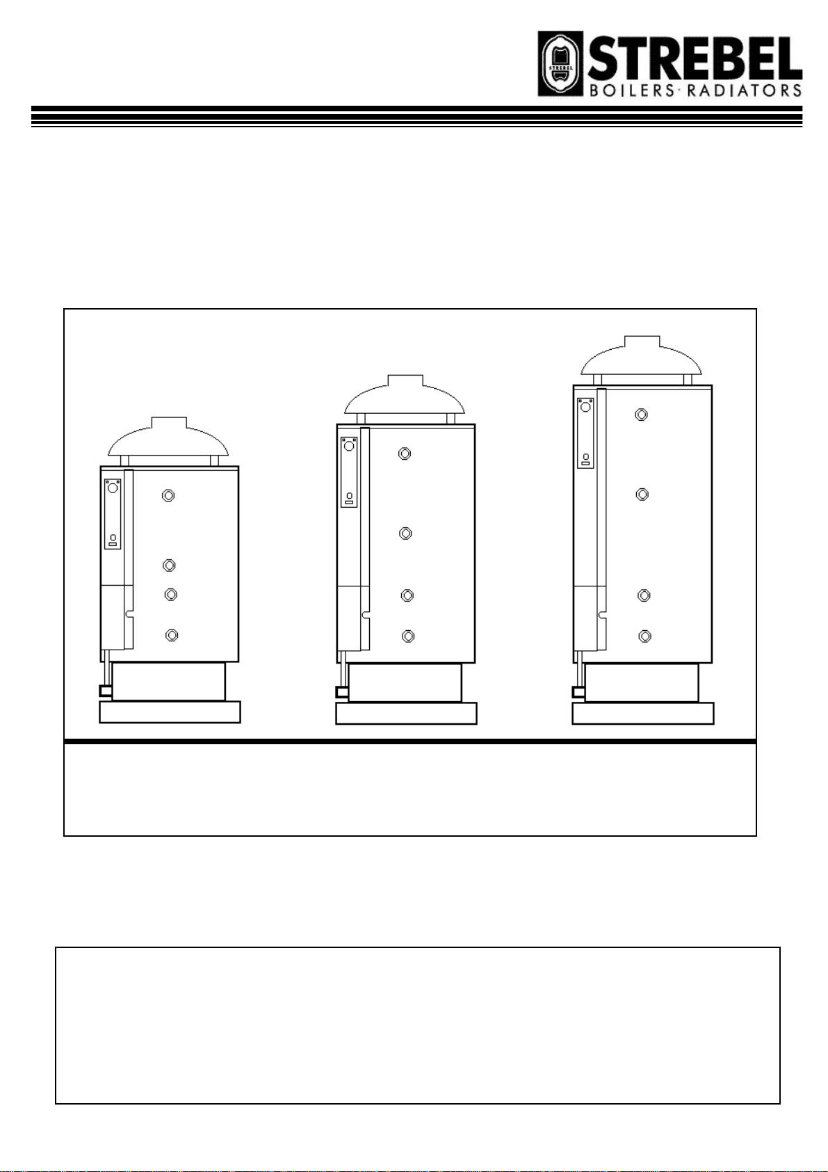
TN 220/300/400
heater for
sanitary hot water production with
Gas fired storage water-
atmospheric burner.
TN 220 – 34 TN 300 – 44 TN 400 – 44
INSTALLATION, OPERATION
& MAINTENANCE MANUAL
Page 1 11/07/00
Page 2

INDEX Page.
GENERAL INFORMATION AND CHARACTERISTICS
1.1 APPLIANCE’S CLASSIFICATION 3
1.2 PACKAGING CONTENT 3
1.3 CONSTRUCTIONAL AND OPERATIONAL DESCRIPTION 3
1.4 CONTROL AND SAFETY DEVICES 4
1.5 CONTROL PANEL 5
1.6 DIMENSIONS AND CONNECTIONS 6
1.7 TECHNICAL DATA 7
1.8 ELECTRICAL DIAGRAM 7
1.9 EXPLODED VIEW 8
INSTALLATION INSTRUCTIONS
2.1 GENERAL PRECAUTIONS 10
2.2 INSTALLATION RECOMMENDATIONS 10
2.3 LOCATION OF THE APPLIANCE 11
2.4 DRAUGHT DIVERTER INSTALLATION 11
2.5 WATER CONNECTIONS 12
2.6 GAS CONNECTION AND REGULATIONS 12
2.7 GAS SUPPLY CONVERSION 14
2.8 ELECTRICAL CONNECTIONS 15
2.9 STARTING THE WATER-HEATER 15
2.10 CONNECTION OF SEVERAL WATER-HEATERS 15
2.11 FAULT FINDING 15
USER INSTRUCTIONS
3.1 RECOMMENDATIONS FOR THE USER 16
3.2 STARTING THE APPLIANCE 16
3.3 SWITCHING OFF 17
3.4 MAINTENANCE 17
3.5 WARRANTY APPLIES 17
Page 2 11/07/00
Page 3
1.1 APPLIANCE’S CLASSIFICATION
DEFINITION
These appliances are classified as: “Direct gas fired
storage water -heater.
CATEGORY
The category of the appliance is:
II
2H3+……………..
This means that the appliance is suitable for gas of 2nd
family (G20/25) and 3rd family (G30/31).
TYPE
Following the European Regulation EN 483, the appliance is of kind B
be connected to a flue gas system for the gas exhausting
outside the room in which it is installed and where the
combusting air is taken directly from the room where
the appliance is installed”. The appliance:
• is supplied with draught diverter in the combustion
products circuit;
• is supplied with a control device for flue gas spill-
age.
•
Great Britain & Ireland
, that means an “appliance settled to
11BS
1.2 PACKAGING CONTENT
The appliance is delivered packaged in a wooden crate
with appropriate protections.
The draught diverter is delivered in a separate cardboard
box, not assembled.
An envelope contains this booklet, the warranty paper
and screws to fix the draught diverter.
1.3 CONSTRUCTIONAL AND OPERATIONAL DESCRIPTION
The appliance is manufactured according to the EC
regulation 90/396(CEE for gas appliances, and has
therefore, the CE agreement. In particular the manufacturing process and the components satisfy the technical
European regulation EN 89.
The purpose of this appliance is to allow the heat exchange between the gas combustion products, burned in
the combustion chamber and the water inside the tank.
The combustion chamber is placed in the lower part of
the appliance, under the water tank. On the top is the
draught diverter.
Flue pipes, which go through the water tank, allow the
exhausting of the gas of the combustion chamber into
the chimney flue and for the thermal exchange. Turbulators have been installed inside the flue exhaust pipes in
order to improve the thermal exchange.
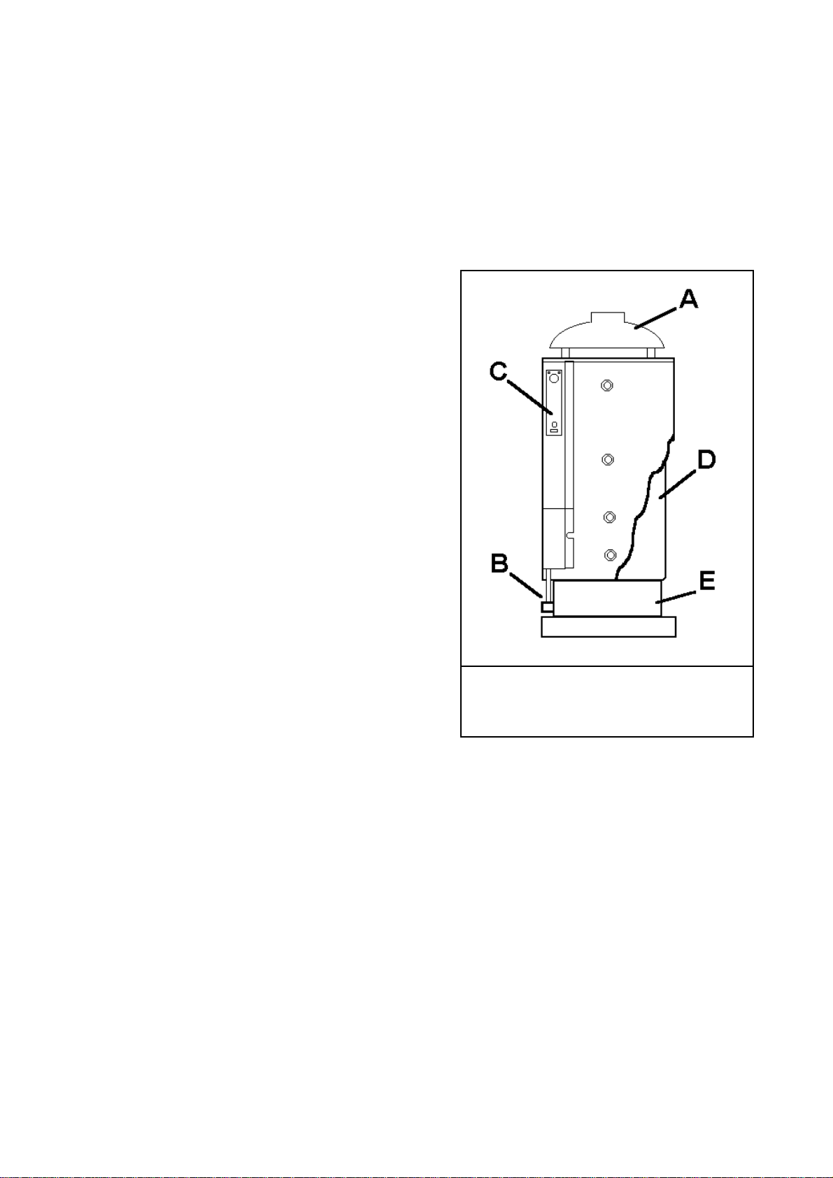
DRAUGHT DIVERTER
It is placed on the combustion products circuit and its
purpose is to keep into pre-set limits the combustion quality
and the combustion stability within min. and max. conditions.
ATMOSPHERIC BURNER
It is composed of two parts: a principal burner, which ensures
the thermal function of the appliance, and a pilot burner
needed to light the principal burner.
fig. 1.3 / 1
A draught diverter B atmospheric burner
C control panel D tank E combustion chamber
CONTROL PANEL
On the instrument control panel there is all required to control
and adjust the normal operation of the appliance: On/Off
switch, water temperature thermostat, water temperature thermometer. There is also the security flue gas spillage thermostat
in case of improper combustion (manual reset) and a red light
which lights up when this thermostat has operated.
TANK
It is made of thick sheet steel and assures great resistance to
pressure. The inside is coated with opal glass (a vitreous coating baked at over 850°).
This allows a high chemical resistance to organic solvents and
many other chemical substances, excellent abrasion resistance
(low friction) and very good thermal stability. This allows
long-life and a higher quality water. Inspection and cleaning of
the tank are allowed by an appropriate clean out and inspection
door.
Page 3 11/07/00
Page 4
COMBUSTION CHAMBER
It is placed in the lower part of the appliance and holds
the atmospheric burner, flame control sensor
(thermocouple) and the pilot burner with ignition electrode.
1.4 CONTROL AND SAFETY DEVICES
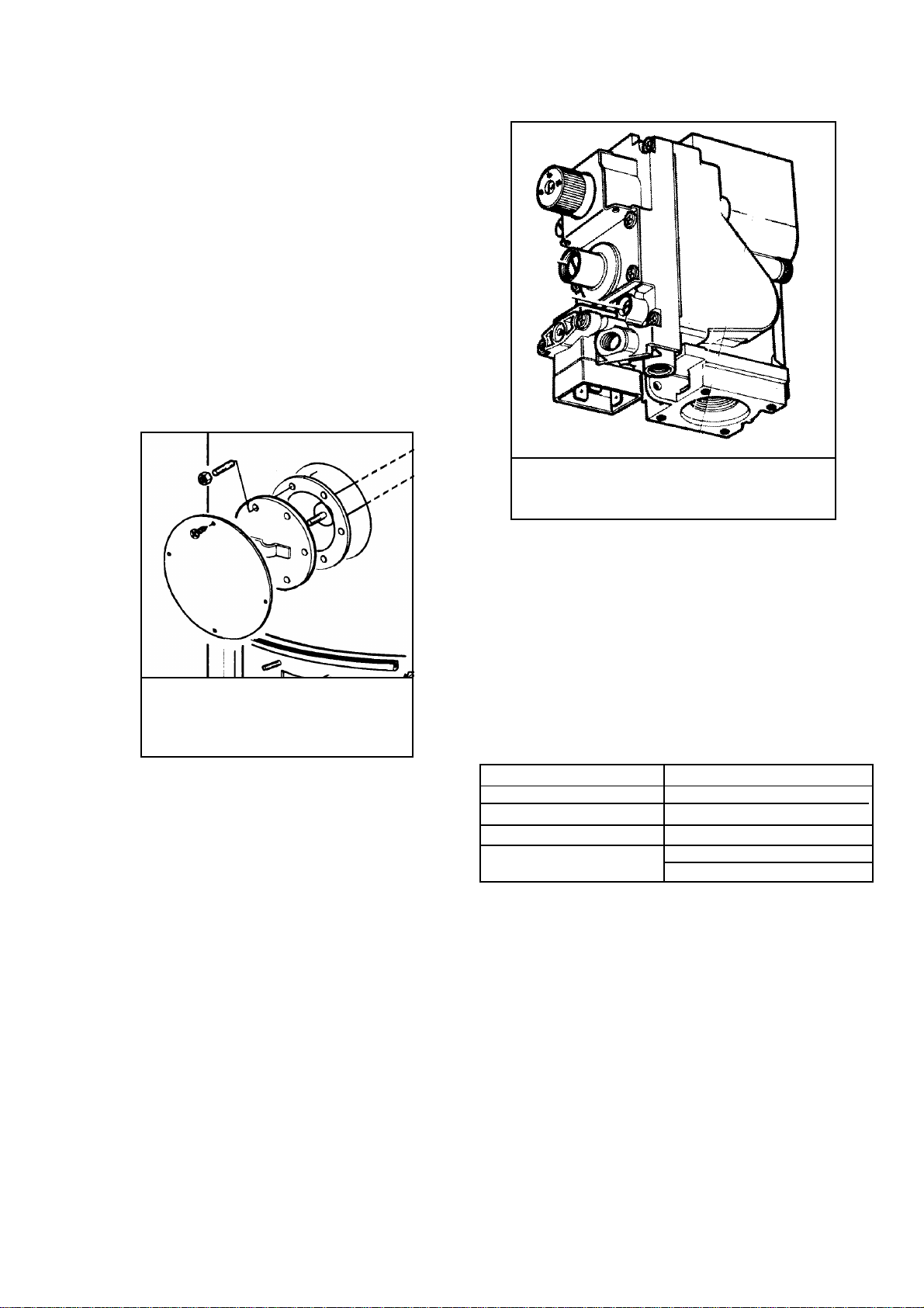
MAGNESIUM ANODE
The water heater is protected against metal-to-metal corrosion by a magnesium anode. It has to be replaced every
year in order to extend the working life of the appliance.
The anode is placed in the inspection flange, on the front
of the tank.
fig. 1.4 / 1
Anode position
GAS VALVE
It is GASTEC approved following the EN 126 regulation.
It is a multi-functional valve with on -off gas flow control
with double electro-valve. The operation happens through
one of 3 positions of control (ignition-workingextinguish).
The inlet and outlet gas connections are threaded 1/2 RP”
UNI-ISO 7, whereas the fitting for the thermocouple is
M9x1. There also are two (inlet and outlet) Two pressure
test point are in the inlet and outlet. Gas valve has a gas
filter at the entry.
fig. 1.4 / 2
Gas valve
All the setting and regulation operations have to be made
by professional qualified people. In case of valve replacement, be sure that the gas flow is in the direction of the arrow on the body the valve and while installing care should
be taken to ensure no foreign matter enters into the valve.
MAINTENANCE: the only operation allowed is the solenoid replacement, which has to be carried out by qualified
personnel..
Gas inlet max. pressure 60 mbar
Pressure outlet range 3 - 30 mbar
Voltage rating 220/240V 50 Hz
Pressure setting B class
Flame detection ignition time < 10 sec
switching time < 60 sec
Pressure safety valve.
We recommend a suitable safety valve is installed.
ADJUSTABLE CONTROL THERMOSTAT 40-80 °C
(VDE (Germany) and IMQ (Italy) approved).
It controls the operation of the appliance switching the
burner on and off, according to the water temperature set.
This is a single pole liquid filled sensing bulb with operating switch contacts.
SAFETY LIMIT THERMOSTAT
(Flue gas spillage control)
It cuts off the burner operating (by cutting the current to
Page 4 11/07/00
Page 5

Control thermostat – Technical data
Temperature range 40º / 80º
Contacts rating 250 V ~ / 2.5 A
Temperature differential 8º ± 2º K
Bulb max. temperature 150º C
the gas valve) in case of improper exhausting of the combustion gas. To restore the normal operation it has to be
manually reset. It is a single pole, liquid filled type, temperature limiter with manual reset and positive cut off
safety in case of capillary breakage.
SAFETY LIMIT THERMOSTAT
(WATER MAX. TEMPERATURE)
It cuts off the burner in case of overheating of the water
tank, due to non-working of the adjustable control thermostat. The operation is automatic (automatic reset) as soon
as the water temperature reaches standard levels/values. It
is a single pole liquid filled type thermostat and two contacts (On/Off switch), safety limit temperature with automatic reset, with positive cutoff safety in case of capillary
breakage. The high limit temperature is factory set at 90°.
Safety limit thermostat (flue gas spillage control)
- Technical data
Intervention temperature 70º ±3º
Differential 15º
Contacts rating 250 V ~ / 2.5 A
Bulb max. temperature 125 ºC
1.5 CONTROL PANEL
Safety limit thermostat (max. water temp.)
Technical data
Intervention temperature 90º ±3º
Differential 12º
Contacts rating 250 V ~ / 2.5 A
Bulb max. temperature 125 ºC
Contacts resistance < 8 mO
KEY:
A – ON/OFF Switch
B – Adjustable water control
thermostat
C – Safety limit thermostat
D – Water temperature
thermometer
E – Safety limit thermostat (on)
light
Page 5 11/07/00
Page 6
1.6 DIMENSIONS AND CONNECTIONS
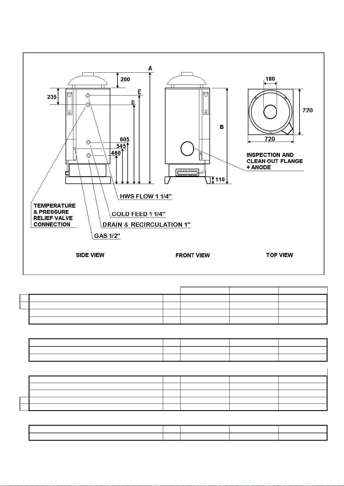
Fig. 1.6/1
A
OVERALL HEIGHT
B
HEIGHT WITHOUT DRAUGHT DIVERTER
WIDTH
DEPTH
BASE
HEIGHT
WIDTH
DEPTH
HEIGHT FROM FLOOR:
DRAIN CONNECTION
GAS CONNECTION
COLD WATER FEED CONNECTION
D
RECIRCULATION CONNECTION
E
HOT WATER CONNECTION
1" 460 mm 460 mm 460 mm
1/2" 545 mm 545 mm 545 mm
1"1/4 605 mm 605 mm 605 mm
1" 1010 mm 1010 mm 1175 mm
1"1/4 1330 mm 1680 mm 2030 mm
INSPECTION AND CLEANING FLANGE
DIAMETER
HEIGHT FROM FLOOR
MOD. 220 MOD. 300 MOD. 400
1600 mm 1960 mm 2310 mm
1400 mm 1750 mm 2100 mm
720 mm 720 mm 720 mm
720 mm 720 mm 720 mm
110 mm 110 mm 110 mm
720 mm 720 mm 720 mm
720 mm 720 mm 720 mm
120 mm 120 mm 120 mm
620 mm 620 mm 620 mm
Page 6 11/07/00
Page 7
1.7 TECHNICAL DATA
STORAGE CAPACITY litre 220 300 400
NOMINAL INPUT Kcal/h 29.420 37.840 37.840
KW 34,0 44,0 44,0
NOMINAL OUTPUT Kcal/h 25.880 33.530 34.590
KW 30,1 39,0 40,2
COMBUSTION EFFICIENCY % 88.5 88.6 91.4
WATER EFFICIENCY % 845 84.2 86.5
TIME TO RECOVER AT 40°C (inlet cold water 15°C) min 13 14 18
CONTIN. OUTPUT AT 40°C (inlet cold water 15°C) lt/hr 988 1.274 1.309
INJECTORS - PRINCIPAL BURNER N° 4 4 4
GAS INPUT RATE G20 20 mbar (NATURAL GAS) m3/h 3,60 4,65 4,65
INJECTOR DIAMETER mm 2,60 3,00 3,00
INJECTOR PRESSURE mbar 10,5 10,5 10,5
GAS INPUT RATE G30/31 29 mbar (LPG) kg/h 2,68 3,46 3,46
INJECTOR DIAMETER mm 1,50 1,75 1,75
INJECTOR PRESSURE WITH G30 (BUTANE) mbar 28,0 28,0 28,0
INJECTOR PRESSURE WITH G31 (PROPANE) mbar 36,0 36,0 36,0
PILOT BURNER INJECTOR DIAMETER (G20)
PILOT BURNER GAS RATE (G20)
PILOT BURNER INJECTOR DIAMETER (G30/31)
PILOT BURNER GAS RATE (G30/31)
VOLTAGE SUPPLY volts 220-240 220-240 220-240
FREQUENCY SUPPLY Hz 50 50 50
TOTAL POWER CONSUMPTION w 7 7 7
MAX WATER PRESSURE bar 6 6 6
WEIGHT kg 160 202 243
MODEL 220-34 300-44 400-44
mm
W
mm
W
0,40
190
0,21
142
0,40
190
0,21
142
0,40
190
0,21
142
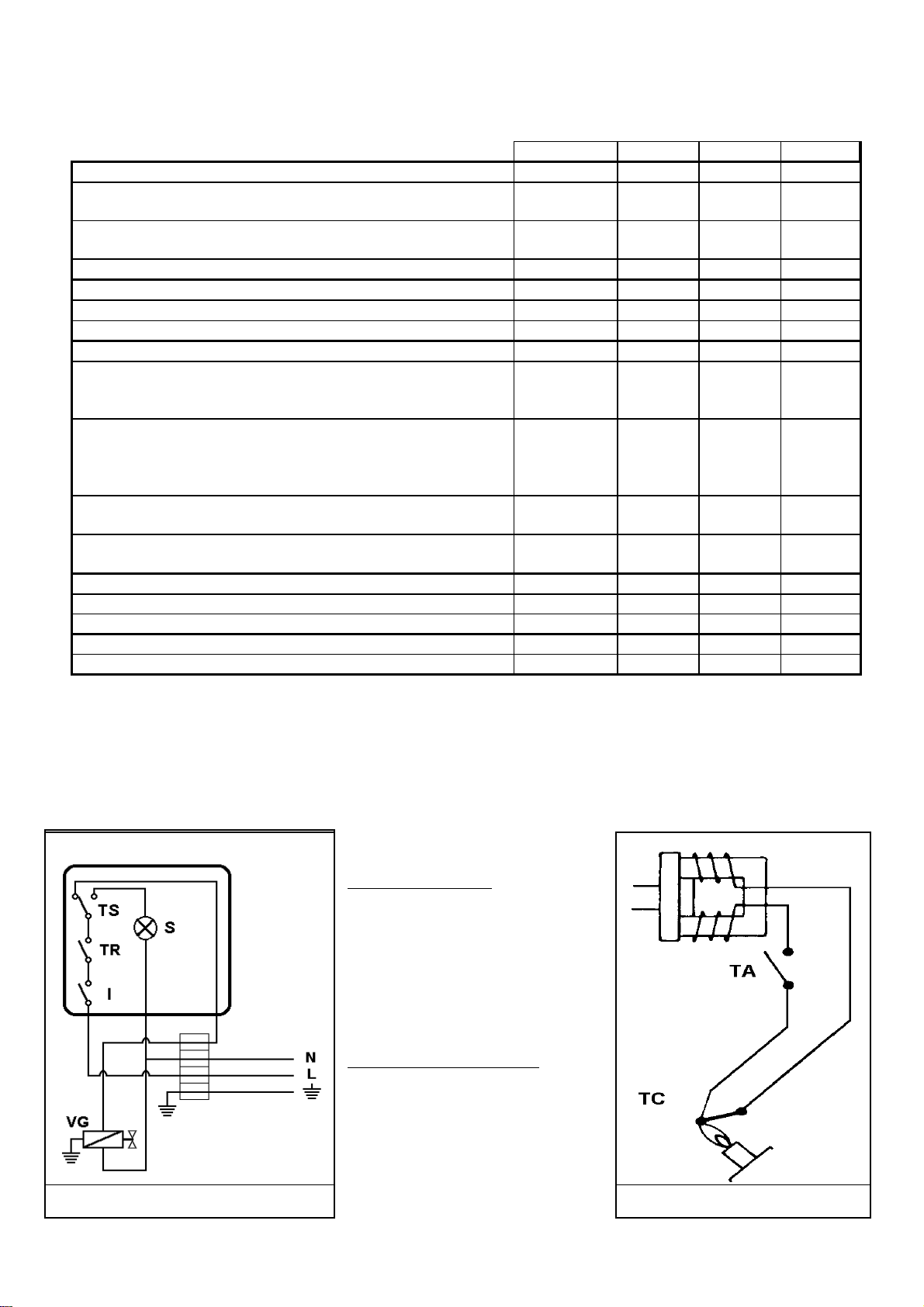
1.8 ELECTRICAL DIAGRAM
KEY:
PRINCIPLE CIRCUIT
I ON/OFF Switch
TR Water temperature thermostat
TS Flue gas safety thermostat
S Max. water temperature light
VG Double gas electrovalve
THERMOCOUPLE CIRCUIT
TA High limit thermostat
TC Flame detection thermocouple
Thermocouple circuit Principle circuit
Page 7 11/07/00
Page 8
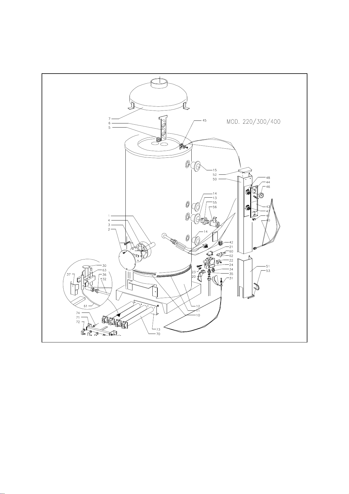
1.9 EXPLODED VIEW
Page 8 11/07/00
Page 9

COMPONENTS LIST
(for exploded view on previous page)
POS. DESCRIPTION POS. DESCRIPTION
Magnesium anode
1
Flange cover
2
Clean out/inspection flange
3
Clean out/inspection flange gasket
4
Plug 1"1/4
5
Flue baffle
6
Draught diverter
7
Casing lower gasket
10
Glass-wool insulation
11
Insulation support ring
12
Blue 1"1/4 PVC Wall-cover
13
Black 1” PVC Wall-cover
14
Red 1”1/4 PVC Wall-cover
15
Connector for valve (screws+gasket)
20
1/2" elbow connection (screws+O-ring)
21
Bracket for gas valve
22
No-hole plug for LPG
23
Gas valve
24
Pilot burner
30
Interrupted thermocouple
31
Gas pipe pilot burner
32
Gas pipe burner
33
Diaphragm (France and Belgium)
34
Double screw 1/2"
35
Nut fitting
36
Pilot protection cover
37
Wiring
40
41
42
43
44
45
46
47
48
50
51
52
53
55
56
60
61
62
63
70
71
72
73
74
ON/OFF Switch
Terminal board
Instrument control panel
Safety limit thermostat (on) light
Bracket for flue safety bulb (2pcs.)
Thermometer
Adjustable control thermostat
Safety limit flue thermostat
Channeling
Module channeling
Channeling cover
Channeling lower seal
1"1/4 - 1" nipple
1" non-return and safety valve
Piezoelectric ignition
Ignition cable
Piezo ignition bracket (with screws)
Ignition electrode
Burner
Burner pipe collector
Burner fixing bracket
Burner rear bracket
Injector
Page 9 11/07/00
Page 10

•2.1 GENERAL PRECAUTIONS
•This booklet is integral and essential part of the
appliance, and it has to be kept with care near the
appliance, for any further consultation.
•The appliance has been manufactured for hot water
production: any other use of it has to be considered
dangerous and not suitable.
•These instructions must be read thoroughly before
proceeding, failure to follow the instructions may affect the
safety, performance and warranty of the appliance.
•Installation must be carried out by professional, qualified
CORGI REGISTERED ENGINEERS in compliance with
all current regulations and manufacturers instructions.
•The installation of the water heater must also be in
accordance with the current I.E.E Regulations, the By-laws
of the Local Water Undertaking, Local Authority
requirements and all relevant British Standards.
2.2 INSTALLATION
RECOMMENDATIONS
During installation and maintenance, respect carefully the
instructions contained in this booklet. Changes of any
connections or the non-observance of these instructions will
cause the warranty to be invalidated.
Before every operation of installation, maintenance or
repairing, remember to isolate the electrical supply to the
appliance.
•The appliance must be installed in a suitable environment
that is NOT explosive, flammable, corrosive or damp.
•Neither the supplier or the manufacturer will be
responsible for any damage to property, persons, animals
or the boiler, as a result of tampering, improper use,
installation or maintenance.
•Packaging parts ( I.e. plastic bags, polystyrene, wood,
clips, nails, etc.) can be harmful to children and must be
disposed of immediately and correctly.
•To avoid damage caused by low temperatures it is
recommended that the water heater should be drained
down if left unused for a long period. Neither the supplier
or manufacturer is responsible for any consequential
damage caused by low temperature.
•To comply with the warranty these instructions must be
adhered to and any original spare parts and kits used.
•In the event of breakdown the appliance should be
isolated and a qualified CORGI REGISTERED SERVICE
ENGINEER contacted.
•The appliance MUST have an annual service and
inspection by a qualified CORGI REGISTERED
ENGINEER.
Page 10 11/07/00
Page 11
2.3 LOCATION OF THE APPLIANCE
As a type B appliance, it is to be installed to a conventional
flue system exiting the external of the room in which it is installed; the combustion air is taken directly from the room
where the appliance is situated.
The vents may be either situated direct to outside air or to an
adjacent room or internal space which must itself have a permanent air vent of at least the same size direct to the outside
air. The minimum effective area of the permanent air vents is
specified below and is related to the maximum rated heat output of the boiler.
ATTENTION: this appliance can be installed and working
only in permanently ventilated rooms.
Do not leave inflammable material close to the appliance, especially in front of (leave at least 50 cm from the opening of the
burner) and close to the draught diverter.
Note:
Both air vents must communicate with the same room or internal space or must both be on the same wall to outside air.
The use of mechanical ventilation for combustion and ventilation air must conform to C.P.332: Part 3.
Ventilation and combustion sir flows must be proved before
the boiler is allowed to operate.
Position of air
vents
High level 9 cm per kW 5 cm per kW
Low level 18 cm per kW 10 cm per kW
AIR VENT AREAS
Air from room or
internal space
(2 in per 5000 Btu/h) (1in per 5000 Btu/h)
(4 in per 5000 Btu/h) (2 in per 5000 Btu/h)
Air direct from
outside
2.4 DRAUGHT DIVERTER INSTALLATION
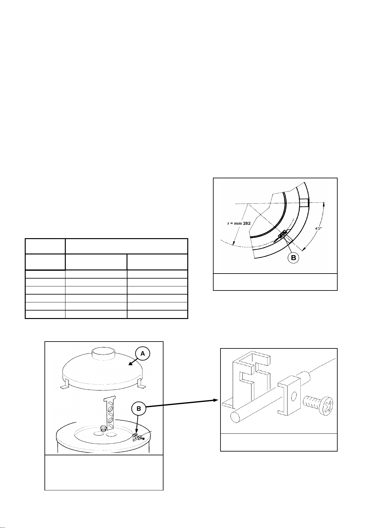
fig. 2.4 / 1
draught diverter (A), flue safety device (B)
The draught diverter A (not assembled - separately supplied)
has to be placed on the upper part of the appliance and fixed
to the appliance itself through the screws supplied.
Connect the flue gas system to the draught diverter, whose
diameter has to be larger than the draught diverter’s
(Ø180mm).
Ensure that during the installation or the transport the bulb B
of the flue safety thermostat has not been damaged or moved
from its previous position.
It is absolutely forbidden to tamper or let the flue safety device be out of order.
The proper position of the bulb of the flue safety device is
282 mm from the center of the appliance (73 mm from the
external edge), perpendicular to the radius (see pict. 2.4/2)
and tighten fastened to the proper stirrup (see pict. 2.4/3).
picture 2.4 / 2
The replacement of the flue safety device has to be made
only by professional qualify people and with original spare
parts supplied by the manufacturer.
picture 2.4 / 3
Page 11 11/07/00
Page 12
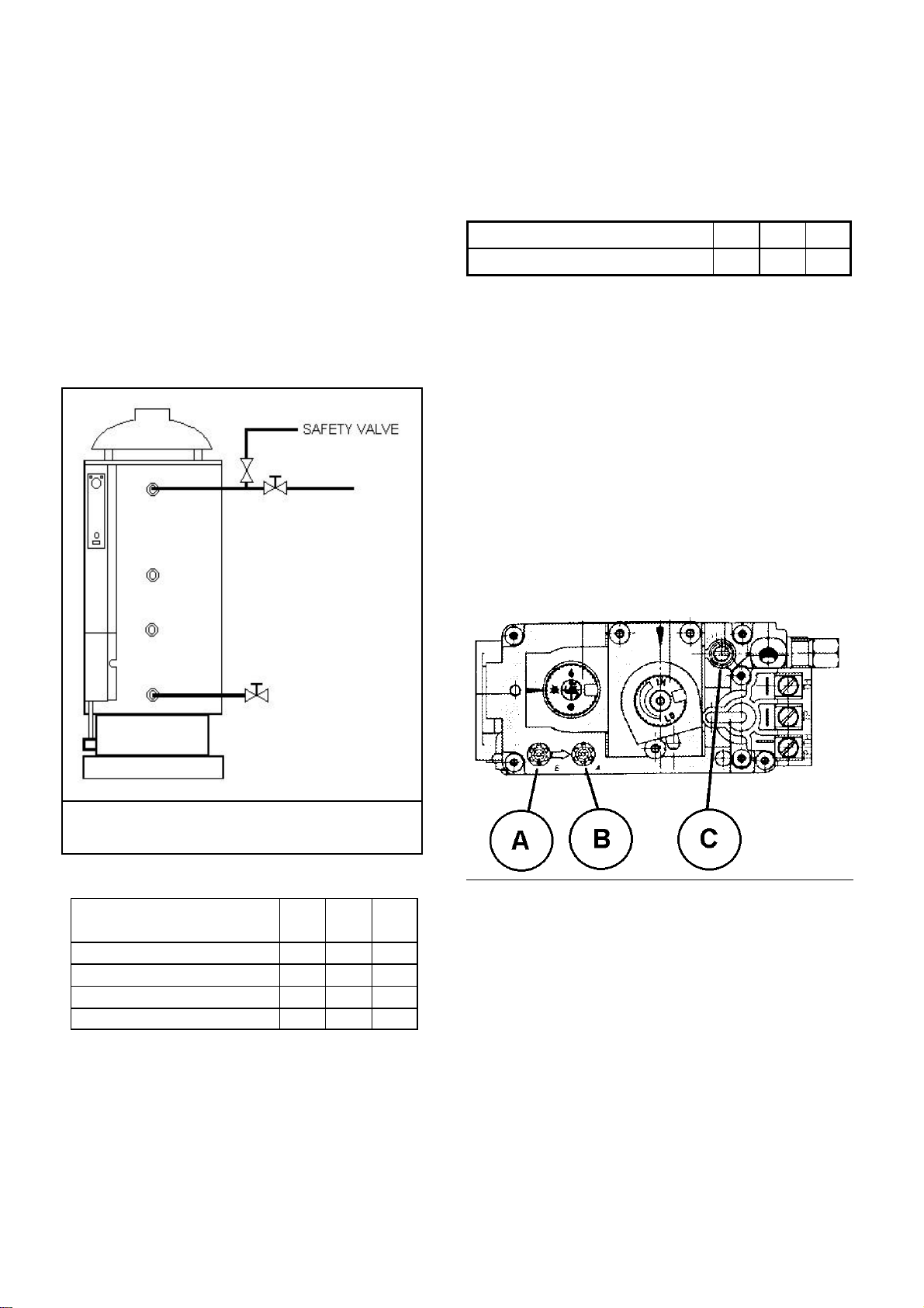
2.5 WATER CONNECTIONS
A: Hot water outlet
Connect the supply line to the hot water
services, providing a safety valve and
isolating cock.
B: Spare tapping
C: Cold water inlet and stopcock.
D: Drain and recirculation connection.
Connect a dr ain cock.
We advise to insulate the hot water pipes in order to
avoid energy waste.
A
B
2.6 GAS CONNECTION AND
REGULATIONS
MODEL 220 300 400
GAS CONNECTION 1/2” 1/2” 1/2”
A manual gas isolating cock is required adjacent to the unit.
NOTE: for system operating with LPG gas it is necessary to
fit a “first stage” pressure reducer close to the tank in order
to reduce the pressure to 1,5 bar . A “second stage” pressure
reducer of adequate capacity should be installed close to
each heater in order to reduce the supply pressure to 30
mbar according to UNI-CIG 7432 regulations.
Be sure that the inlet gas pressure of the appliance (through
pressure test point A on the valve) is the one for which the
appliance is set.
C
D
Fig 2.5 / 1
MODEL 220 300 400
COLD WATER INLET 1"1/4 1"1/4 1"1/4
RECIRCULATION 1" 1" 1"
DRAIN 1" 1" 1"
HOT WATER OUTLET 1"1/4 1"1/4 1"1/4
The appliance is set at works for the gas and pressure on the
data label, according to the following:
G20 (H Gas or Natural gas)
• inlet pressure: 20 mbar
• pressure setting: on
• country: Italy, Spain, Portugal, Great Britain, Ireland,
Greece.
Page 12 11/07/00
Page 13
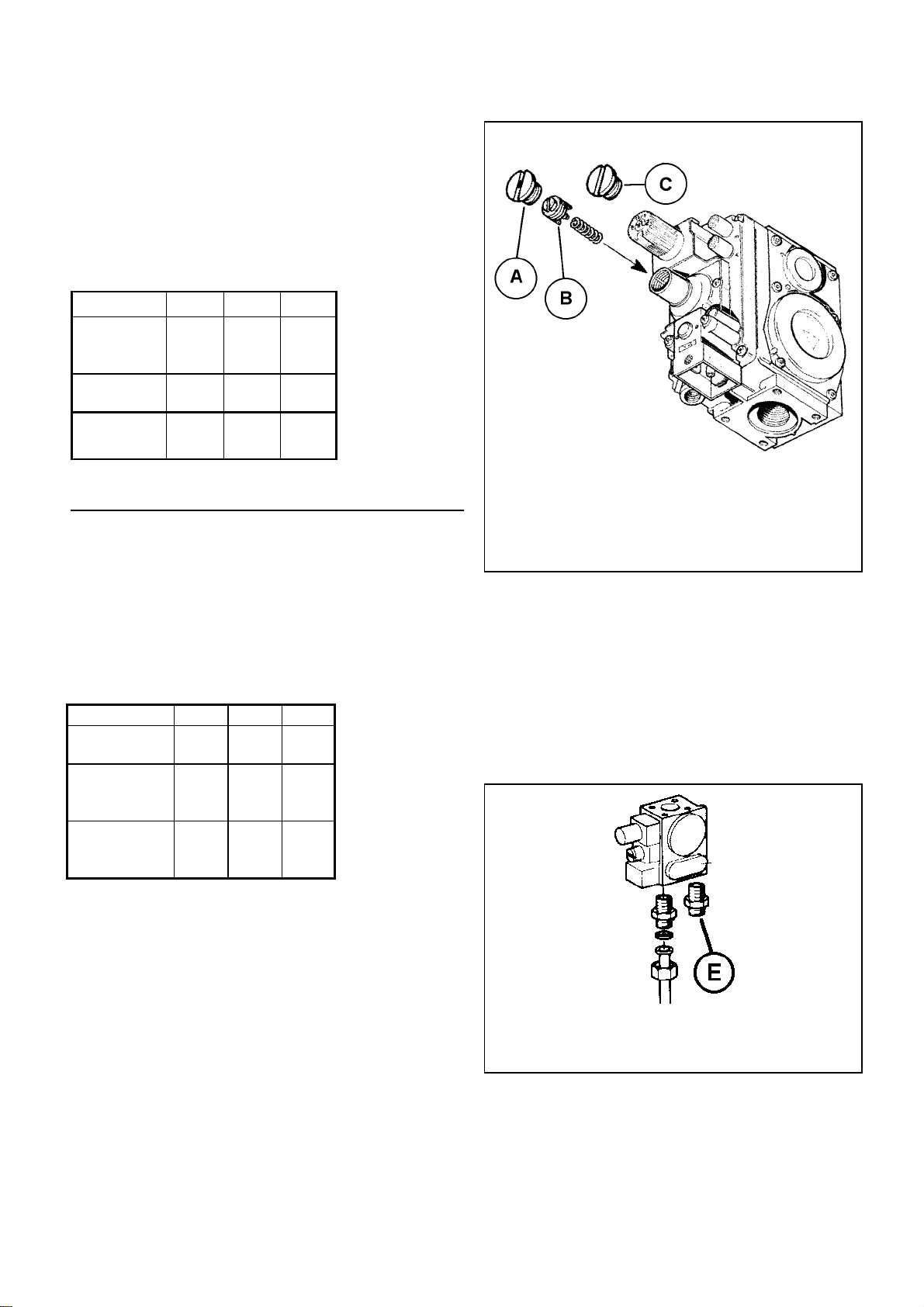
The appliance is set at works for the gas and pressure on
the data label, according to the following:
G20 (H Gas or Natural gas)
• inlet pressure: 20 mbar
• pressure setting: on
• country: Italy, Spain, Portugal, Great Britain, Ireland,
Greece.
MODEL 220-34 300-44 400-44
gas pressure at
10.5 10.5 10.5
injector
(mbar)
injectors
diameter
diaphragm
2.60 3.00 3.00
5.00 5.00 5.70
diameter
pair G30/31 (LPG or butane/propane)
• inlet pressure: 28-30/37 mbar
• pressure setting: off
• country: Italy, Spain, Portugal, Great Britain, Ireland,
Greece, The Netherlands, France, Belgium.
MODEL 220-34 300-44 400-44
injectors diame-
1.50 1.70 1.70
ter
gas pressure at
28,0 28,0 28,0
injector butane
G30 (mbar)
gas pressure at
36,0 36,0 36,0
injector prop
G31 (mbar)
fig. 2.6 / 2
plug (A), regulation screw (B) plug without vent hole(C)
SETTING WITH PRESSURE SETTING OFF
Pair G30/31 (LPG or butane/propane)
In this case the valve pressure setting is disregarded: the A
plug has to be replaced with the non vented plug C. The regulation screw has to be screwed fully clockwise.
SETTING THE GAS PRESSURE
G20 (H gas or natural gas)
Commission the unit as follows:
With the water-heater operating, take off Plug A (pict.
2.6/2), turn the regulation screw B until the pressure corresponds to that in the tables above; clockwise the outlet
pressure increases; anti-clockwise it decreases.
Switch off the appliance and restart for a further check
about 1 minute later. Replace Plug A after setting.
Page 13 11/07/00
fig. 2.6 / 3
plug (A), regulation screw (B) plug without vent hole(C)
Pair G30/31 (LPG or butane/propane)
The A plug has been replaced with the plug C without a vent
hole whereas the regulation screw has been tightened clockwise.
Page 14
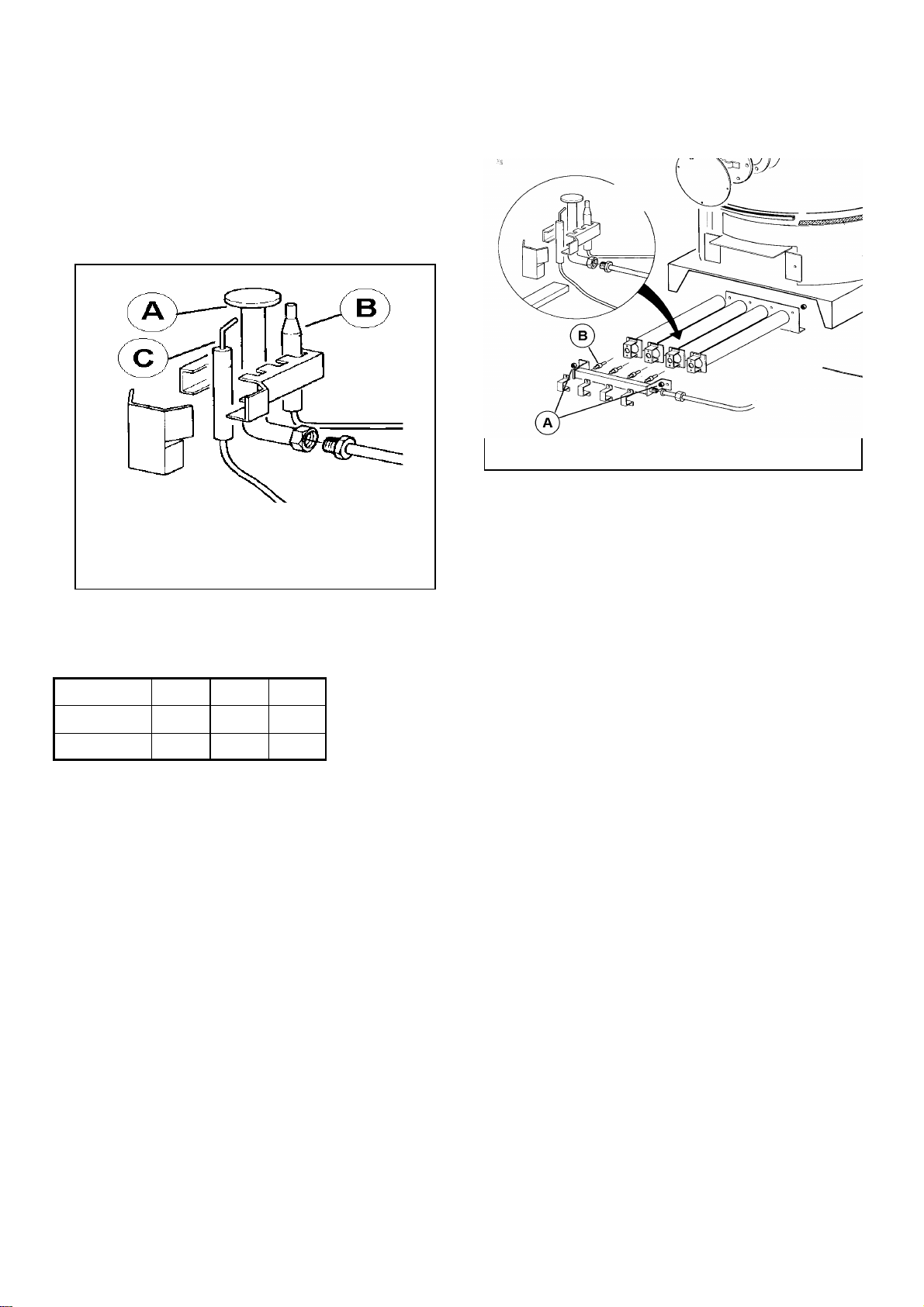
CALIBRATION GAS RATE TO THE PILOT BURNER
If a calibration gas rate to the pilot burner is needed (i.e. if
the flame of the pilot burner is too small or is not well in
touch with the thermocouple) work on the C screw pict. 2.6;
clockwise to decrease the rate; anti-clockwise to increase the
rate.
picture 2.3 / 4
pilot burner (A), flame detection thermocouple (B)
ignition electrode (C)
PILOT BURNER INJECTOR DIAMETER
GAS/MODEL 220-34 300-44 400-44
G20
pair G30/31
0.40 0.40 0.40
0.21 0.21 0.21
2.7 GAS SUPPLY CONVERSION
To convert to LPG gas it is
necessary to use the proper conversion kit supplied by the
manufacturer. Conversion has to be done only by qualified
personnel.
For the gas supply conversion, proceed as follows:
1. Obtain the relevant conversion kit (injectors, diaphragm...).
2. Close the gas isolating cock and isolate the electrical
supply.
3. Extract the burner from its housing by unscrewing the
two securing nuts A, after separating the gas supply pipe.
4. Unscrew the four injectors B and replace them with the
ones in the conversion kit. Fully tighten in order to ensure gas soundness.
5. Work on the gas valve pressure control: if change from
G20 (natural gas) to the LPG the pressure control has to
be adjusted by tightening screwing the regulation screw
B (pict 2.6/2) and replacing the plug A with the special
plug without vest C held in the kit.
6. Adjust the gas supply to the pilot burner to let the flame
of the pilot burner be well in contact with the thermocouple; work on screw C picture 2.6/1: clockwise to decrease, anti-clockwise to increase.
7. Affix the label in the kit on the valve to indicate that the
appliance has been set for the new gas type.
WARNING: LPG gas operation, a “first stage” pressure reducer is needed close to the tank in order to reduce the pressure to 1,5 bar. We also recommend to install a “second
stage“ pressure reducer close to the appliance, in order to reduce the supply pressure to 29 mbar.
IMPORTANT: at the end of setting and regulation operations, check:
1. the electrical isolation of the gas valve connectors
2. the gas soundness
3. the locking of the plug of the pressure test points
4. the proper operating of the appliance
Fig 2.7 /1
Page 14 11/07/00
Page 15
2.8 ELECTRICAL CONNECTIONS
The appliance has to be connected to a 220/240 Volt single-phase supply mains with an efficient earth.
THE MANUFACTURER CAN NOT BE CONSIDERED RESPONSIBLE FOR ANY DAMAGE OR INJURY CAUSED BY FAILURE TO EARTH THE INSTALLATION TO THE REQUIRED STANDARD.
A double pole switch should be fitted close to the appliance to allow the isolation of mains supply.
Connect the equipment supply cable, taking care to comply with the electrical standards.
2.9 STARTING THE WATER-HEATER
Before starting the water-heater ensure that:
• The appliance is set to function with the correct gas
type.
• The regulations about the installation of these appli-
ances are complied with, especially about the proper
connection of the flue and the gas supply piping.
• The electrical supply is on and earthing has been car-
ried out in accordance with current regulations.
• The gas isolating cocks at the meter and in the vicinity
of the heater are open.
• The water heater is full of water.
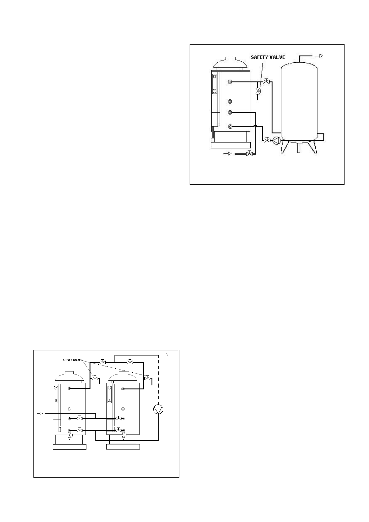
2.10 CONNECTION OF SEVERAL WATER-HEATERS
When several water-heaters have to be connected together it is important to connect them in such a way that
they can operate individually or together.
This is possible by using valves in the circuit, whose
opening and closure allow to decide how many appliances to use according to needs (i.e. low and high seasons, peak periods, repair of equipment, etc).
For example we suggest the following types of layouts:
Fig 2.9 / 1
Two appliances connected in parrallel
Fig 2.9 / 2
Water heater with storage cylinder connected in series
2.11 FAULT FINDING
The flame of the pilot burner does not form:
• The gas isolating cock is closed or there is no gas supply
• The pilot burner injector is blocked
• The ignition cable is broken or not well connected to the
ignition electrode
• The high limit thermostat is working (water max. tem-
perature) on the thermocouple circuit.
The flame of the pilot burner does not keep burning:
• Set the pilot burner gas rate with the adjustment screw
• Thermocouple is damaged or not in the flame
• Gas valve is faulty (to be replaced)
The principal burner switches on with a noisily:
• The pilot burner is dirty
• The pilot burner has not been set properly (set flow - par.
2.6)
• The pilot burner is placed improperly
The pilot burner lights the principal burner does not.
• The gas valve control knob is not in the
ON position
• There is no electrical supply
• The gas valve coil is faulty
• The gas valve is broken (replace the gas valve)
• The flue safety thermostat is working and the red light E
(pict. 1.5/1) is on. Unscrew the cover cap C and reset the
thermostat by pushing the button.
ATTENTION:
If the unit still does not function, turn it off and call a qualified engineer.
For safety and warranty validity original components and
spare parts should be used for replacement and installed by
professional qualified people.
Page 15 11/07/00
Page 16
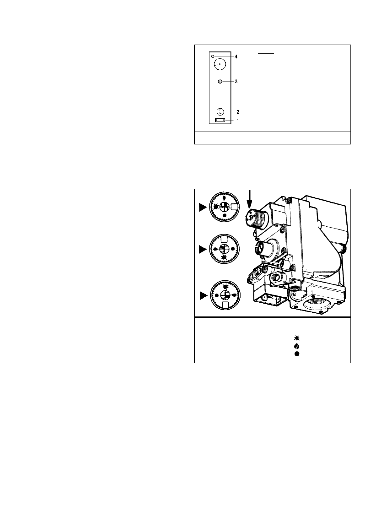
mostat (on)
3.1 RECOMMENDATIONS FOR THE USER
• Keep this booklet with care near the appliance for any fur-
ther consultation.
• For good working and validity of the guarantee, ask for
the unit to be serviced annually by a qualified engineer.
• All the installation operations have to be made exclusively
by professional qualified people in respect of the safety
regulations in force. An incorrect installation, caused by
not observing the manufacturer’s instruction can cause
damage to people, animals or things for which the manufacturer can not be considered responsible.
• The appliance has been manufactured for hot water pro-
duction: any other use of it has to be considered dangerous
and not suitable.
• The appliance is not to be installed in damp rooms; it has
to be protected from water splashes and other liquids, to
avoid anomalies to electrical and thermal devices.
• Installation has to be carried out by professional qualified
people according to the safety regulations in force.
• Packaging parts (i.e. plastic bags, polystyrene, wood,
clips, nails etc.) can be harmful to children and should be
carefully disposed of immediately.
• Read carefully the instructions and the advice contained in
this booklet concerning safety, installation, use and maintenance.
• If the appliance is sold or transferred to a new owner,
make sure that this booklet stays with the appliance, so
that the new owner or installer can consult it.
• Do not place anything upon the appliance.
• To avoid damages caused by low temperatures, if the ap-
pliance has to be left unused for a long period in a nonheated room, it is recommended the unit is drained completely.
• The manufacturer is not responsible for faults, break
downs or for water leakage from the plant caused by low
temperatures.
• To get the best efficiency of the appliance and to comply
with the guarantee, we advise you to adhere to these instructions, to have the appliance checked by professional
qualified people and to use only original spare parts and
kits supplied by the manufacturer.
3.2 STARTING THE APPLIANCE
1. PILOT FLAME IGNITION: push and turn the knob of the
gas valve in the pilot position; push the knob and light the
burner through the piezo-electric ignition on the valve.
Keep the knob pushed for some seconds, and leave it by
checking that the pilot burner flame is established. Repeat
if the pilot flame extinguishes.
2. PRINCIPAL BURNER IGNITION: push and turn the
knob to the On position.
3. set the switch on the ON position “I”;
4. set the control thermostat indicator to the desired water
temperature (min. 40° max. 70°).
KEY:
1 – ON/OFF Switch
2 – Water temperature thermostat
3 – Safety limit thermostat
(exhausting gas)
4 – Safety limit ther
light
Fig 3.2 / 1
To check the operating of the thermostat, turn the knob 2
(pict. 3.2/1) to the lower value and check that the burner extinguishes. Turn the knob again to the previous pre-set value
and check for a proper ignition of the burner.
Fig 3.2 / 1
Gas valve knob
Position:
PILOT
ON
OFF
From this moment on the water heating phase begins: the
burner will operate until the water temperature reaches the
temperature set at point 2: at this moment the principal
burner switches off (the pilot burner remains alight); the
burner will operate again if the temperature goes below the
pre-set value (i.e. a lot of hot water is used).
FLUE GAS SAFETY OPERATING: the appliance has a
flue gas spillage thermostat which operates in case of improper exhausting of the combustion gases (i.e. if the chimney is blocked). If this happens, the red light (4) will be illuminated and the gas supply to the principal burner is
stopped. To reset push the button under the cover cap plug
(3) in order to restart again the appliance.
Page 16 11/07/00
Page 17

If the safety thermostat functions again, switch off the
unit, shut the gas isolating valve and call a qualified engineer.
3.3 SWITCHING OFF
To switch off the water-heater for a short period:
• press the 1 switch pict. 3.2/2 to the “O” position (the
pilot burner will remain alight).
To switch off the water-heater for a lengthy period:
• press and rotate the knob of the gas valve to the OFF
position.
• rotate the knob of the thermostat to the minimum value.
• press the ON/OFF switch to the "0" position.
• switch off the electrical supply by the main isolating
switch.
• close the gas isolating valve.
• if the appliance has to be switched off for a very long
period in a non-heated room, we advise the unit should
be drained completely.
3.4 MAINTENANCE
To ensure the safety of the appliance and to extend its
working life it is recommended that an annual check / service of the unit is done, with consideration of the following:
• Magnesium anode replacement
• Internal inspection of the water tank (and removal of
calcium deposits on the bottom of the tank) through the
inspection and cleaning flange
• Check the gas soundness
• Check the general good operation
3.5 WARRANTY APPLIES
The warranty is valid provided that the installation standards and everything contained in the present booklet are
complied with. The warranty for all devices is 12 months .
Page 17 11/07/00
Page 18

THE COMPANY RESERVES THE RIGHT TO CHANGE SPECIFICATIONS AND DIMENSIONS WITHOUT NOTICE
STREBEL LTD
1F Albany Park Industrial Estate
Frimley Road, Camberley, Surrey, GU16 7PB
Telephone: 01276 685422 Fax: 01276 685405
E-mail address: [email protected]
Website: www.strebel.co.uk
Page 18 11/07/00
 Loading...