

Strebel TN 220, TN 300, TN 400 Installation, Operation & Maintenance Manual
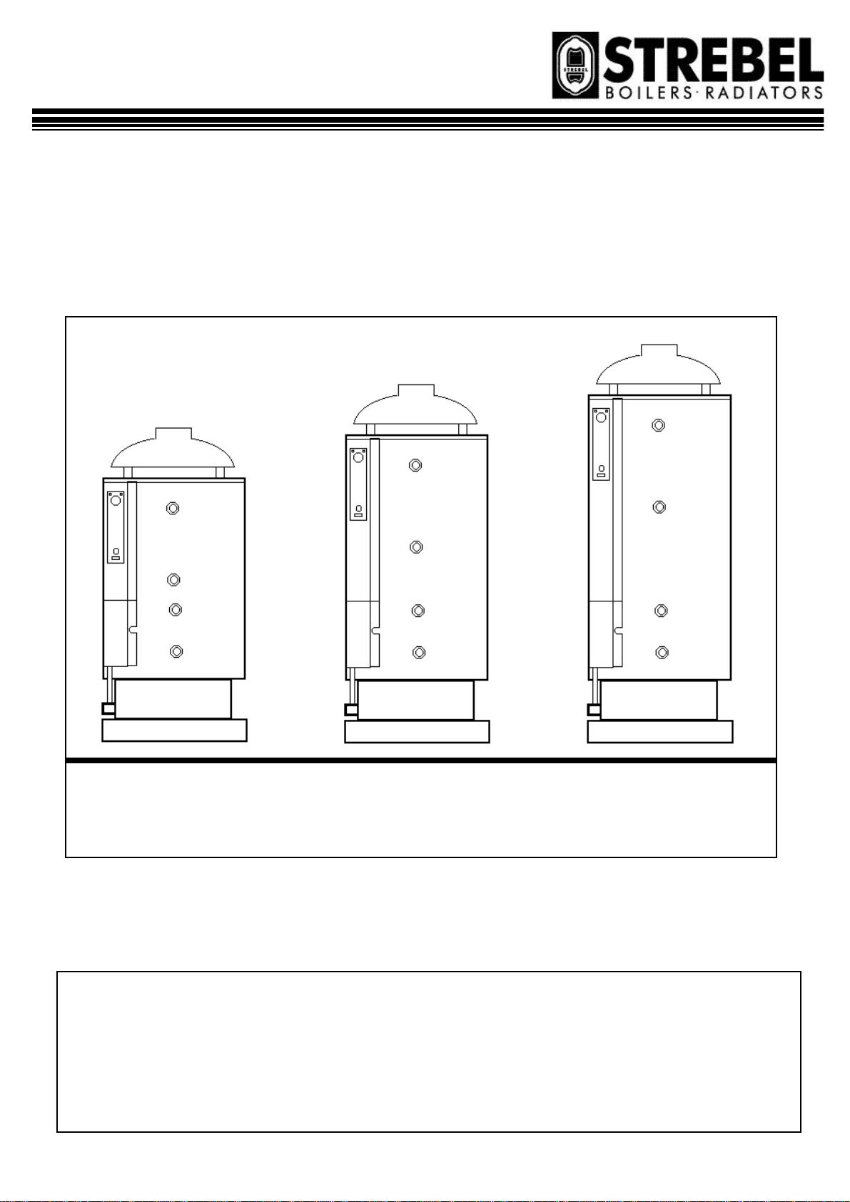
TN 220/300/400
heater for
sanitary hot water production with
Gas fired storage water-
atmospheric burner.
TN 220 – 34 TN 300 – 44 TN 400 – 44
INSTALLATION, OPERATION
& MAINTENANCE MANUAL
Page 1 11/07/00

INDEX Page.
GENERAL INFORMATION AND CHARACTERISTICS
1.1 APPLIANCE’S CLASSIFICATION 3
1.2 PACKAGING CONTENT 3
1.3 CONSTRUCTIONAL AND OPERATIONAL DESCRIPTION 3
1.4 CONTROL AND SAFETY DEVICES 4
1.5 CONTROL PANEL 5
1.6 DIMENSIONS AND CONNECTIONS 6
1.7 TECHNICAL DATA 7
1.8 ELECTRICAL DIAGRAM 7
1.9 EXPLODED VIEW 8
INSTALLATION INSTRUCTIONS
2.1 GENERAL PRECAUTIONS 10
2.2 INSTALLATION RECOMMENDATIONS 10
2.3 LOCATION OF THE APPLIANCE 11
2.4 DRAUGHT DIVERTER INSTALLATION 11
2.5 WATER CONNECTIONS 12
2.6 GAS CONNECTION AND REGULATIONS 12
2.7 GAS SUPPLY CONVERSION 14
2.8 ELECTRICAL CONNECTIONS 15
2.9 STARTING THE WATER-HEATER 15
2.10 CONNECTION OF SEVERAL WATER-HEATERS 15
2.11 FAULT FINDING 15
USER INSTRUCTIONS
3.1 RECOMMENDATIONS FOR THE USER 16
3.2 STARTING THE APPLIANCE 16
3.3 SWITCHING OFF 17
3.4 MAINTENANCE 17
3.5 WARRANTY APPLIES 17
Page 2 11/07/00
1.1 APPLIANCE’S CLASSIFICATION
DEFINITION
These appliances are classified as: “Direct gas fired
storage water -heater.
CATEGORY
The category of the appliance is:
II
2H3+……………..
This means that the appliance is suitable for gas of 2nd
family (G20/25) and 3rd family (G30/31).
TYPE
Following the European Regulation EN 483, the appliance is of kind B
be connected to a flue gas system for the gas exhausting
outside the room in which it is installed and where the
combusting air is taken directly from the room where
the appliance is installed”. The appliance:
• is supplied with draught diverter in the combustion
products circuit;
• is supplied with a control device for flue gas spill-
age.
•
Great Britain & Ireland
, that means an “appliance settled to
11BS
1.2 PACKAGING CONTENT
The appliance is delivered packaged in a wooden crate
with appropriate protections.
The draught diverter is delivered in a separate cardboard
box, not assembled.
An envelope contains this booklet, the warranty paper
and screws to fix the draught diverter.
1.3 CONSTRUCTIONAL AND OPERATIONAL DESCRIPTION
The appliance is manufactured according to the EC
regulation 90/396(CEE for gas appliances, and has
therefore, the CE agreement. In particular the manufacturing process and the components satisfy the technical
European regulation EN 89.
The purpose of this appliance is to allow the heat exchange between the gas combustion products, burned in
the combustion chamber and the water inside the tank.
The combustion chamber is placed in the lower part of
the appliance, under the water tank. On the top is the
draught diverter.
Flue pipes, which go through the water tank, allow the
exhausting of the gas of the combustion chamber into
the chimney flue and for the thermal exchange. Turbulators have been installed inside the flue exhaust pipes in
order to improve the thermal exchange.
DRAUGHT DIVERTER
It is placed on the combustion products circuit and its
purpose is to keep into pre-set limits the combustion quality
and the combustion stability within min. and max. conditions.
ATMOSPHERIC BURNER
It is composed of two parts: a principal burner, which ensures
the thermal function of the appliance, and a pilot burner
needed to light the principal burner.
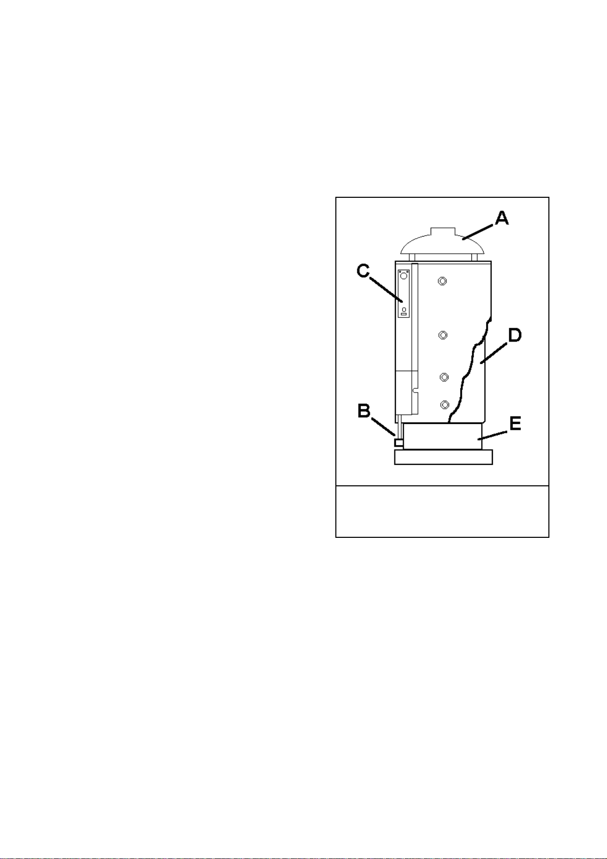
fig. 1.3 / 1
A draught diverter B atmospheric burner
C control panel D tank E combustion chamber
CONTROL PANEL
On the instrument control panel there is all required to control
and adjust the normal operation of the appliance: On/Off
switch, water temperature thermostat, water temperature thermometer. There is also the security flue gas spillage thermostat
in case of improper combustion (manual reset) and a red light
which lights up when this thermostat has operated.
TANK
It is made of thick sheet steel and assures great resistance to
pressure. The inside is coated with opal glass (a vitreous coating baked at over 850°).
This allows a high chemical resistance to organic solvents and
many other chemical substances, excellent abrasion resistance
(low friction) and very good thermal stability. This allows
long-life and a higher quality water. Inspection and cleaning of
the tank are allowed by an appropriate clean out and inspection
door.
Page 3 11/07/00
COMBUSTION CHAMBER
It is placed in the lower part of the appliance and holds
the atmospheric burner, flame control sensor
(thermocouple) and the pilot burner with ignition electrode.
1.4 CONTROL AND SAFETY DEVICES
MAGNESIUM ANODE
The water heater is protected against metal-to-metal corrosion by a magnesium anode. It has to be replaced every
year in order to extend the working life of the appliance.
The anode is placed in the inspection flange, on the front
of the tank.
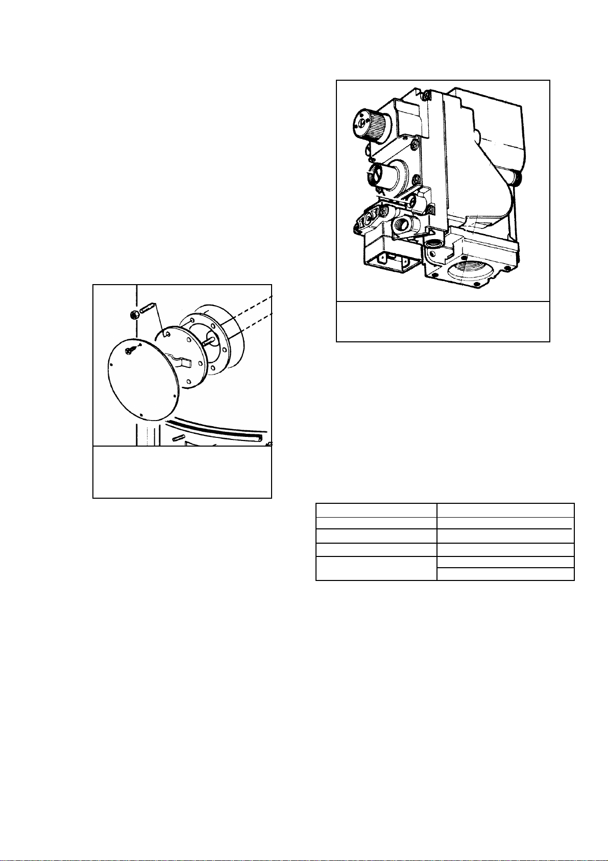
fig. 1.4 / 1
Anode position
GAS VALVE
It is GASTEC approved following the EN 126 regulation.
It is a multi-functional valve with on -off gas flow control
with double electro-valve. The operation happens through
one of 3 positions of control (ignition-workingextinguish).
The inlet and outlet gas connections are threaded 1/2 RP”
UNI-ISO 7, whereas the fitting for the thermocouple is
M9x1. There also are two (inlet and outlet) Two pressure
test point are in the inlet and outlet. Gas valve has a gas
filter at the entry.
fig. 1.4 / 2
Gas valve
All the setting and regulation operations have to be made
by professional qualified people. In case of valve replacement, be sure that the gas flow is in the direction of the arrow on the body the valve and while installing care should
be taken to ensure no foreign matter enters into the valve.
MAINTENANCE: the only operation allowed is the solenoid replacement, which has to be carried out by qualified
personnel..
Gas inlet max. pressure 60 mbar
Pressure outlet range 3 - 30 mbar
Voltage rating 220/240V 50 Hz
Pressure setting B class
Flame detection ignition time < 10 sec
switching time < 60 sec
Pressure safety valve.
We recommend a suitable safety valve is installed.
ADJUSTABLE CONTROL THERMOSTAT 40-80 °C
(VDE (Germany) and IMQ (Italy) approved).
It controls the operation of the appliance switching the
burner on and off, according to the water temperature set.
This is a single pole liquid filled sensing bulb with operating switch contacts.
SAFETY LIMIT THERMOSTAT
(Flue gas spillage control)
It cuts off the burner operating (by cutting the current to
Page 4 11/07/00

Control thermostat – Technical data
Temperature range 40º / 80º
Contacts rating 250 V ~ / 2.5 A
Temperature differential 8º ± 2º K
Bulb max. temperature 150º C
the gas valve) in case of improper exhausting of the combustion gas. To restore the normal operation it has to be
manually reset. It is a single pole, liquid filled type, temperature limiter with manual reset and positive cut off
safety in case of capillary breakage.
SAFETY LIMIT THERMOSTAT
(WATER MAX. TEMPERATURE)
It cuts off the burner in case of overheating of the water
tank, due to non-working of the adjustable control thermostat. The operation is automatic (automatic reset) as soon
as the water temperature reaches standard levels/values. It
is a single pole liquid filled type thermostat and two contacts (On/Off switch), safety limit temperature with automatic reset, with positive cutoff safety in case of capillary
breakage. The high limit temperature is factory set at 90°.
Safety limit thermostat (flue gas spillage control)
- Technical data
Intervention temperature 70º ±3º
Differential 15º
Contacts rating 250 V ~ / 2.5 A
Bulb max. temperature 125 ºC
1.5 CONTROL PANEL
Safety limit thermostat (max. water temp.)
Technical data
Intervention temperature 90º ±3º
Differential 12º
Contacts rating 250 V ~ / 2.5 A
Bulb max. temperature 125 ºC
Contacts resistance < 8 mO
KEY:
A – ON/OFF Switch
B – Adjustable water control
thermostat
C – Safety limit thermostat
D – Water temperature
thermometer
E – Safety limit thermostat (on)
light
Page 5 11/07/00
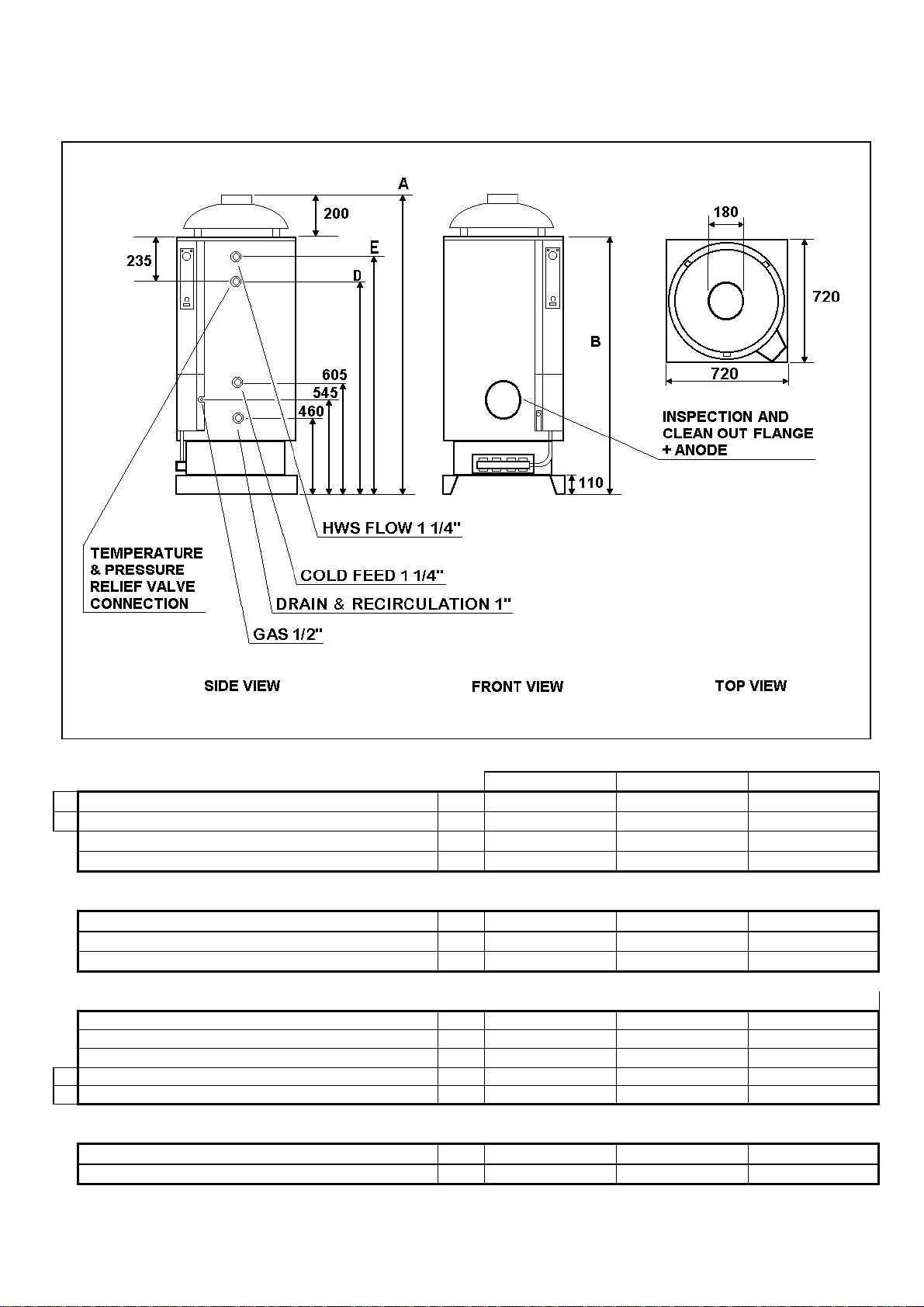
1.6 DIMENSIONS AND CONNECTIONS
Fig. 1.6/1
A
OVERALL HEIGHT
B
HEIGHT WITHOUT DRAUGHT DIVERTER
WIDTH
DEPTH
BASE
HEIGHT
WIDTH
DEPTH
HEIGHT FROM FLOOR:
DRAIN CONNECTION
GAS CONNECTION
COLD WATER FEED CONNECTION
D
RECIRCULATION CONNECTION
E
HOT WATER CONNECTION
1" 460 mm 460 mm 460 mm
1/2" 545 mm 545 mm 545 mm
1"1/4 605 mm 605 mm 605 mm
1" 1010 mm 1010 mm 1175 mm
1"1/4 1330 mm 1680 mm 2030 mm
INSPECTION AND CLEANING FLANGE
DIAMETER
HEIGHT FROM FLOOR
MOD. 220 MOD. 300 MOD. 400
1600 mm 1960 mm 2310 mm
1400 mm 1750 mm 2100 mm
720 mm 720 mm 720 mm
720 mm 720 mm 720 mm
110 mm 110 mm 110 mm
720 mm 720 mm 720 mm
720 mm 720 mm 720 mm
120 mm 120 mm 120 mm
620 mm 620 mm 620 mm
Page 6 11/07/00
 Loading...