

Strebel S-WG 100, S-WG 80, S-WG 120, S-WG 150, S-WG 180 Installation, Operating And Maintenance Manual
STREBEL
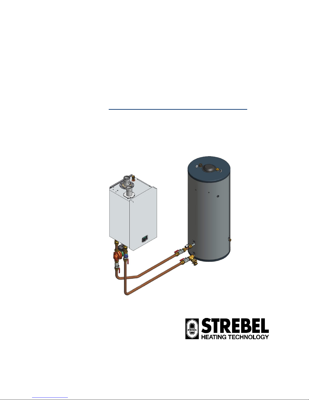
S-WG
80 - 100 - 120 - 150 - 180
Wall hung high efficiency water heater
Installation, Operating and Maintenance Manual
2015-05-06 v2.1

E09.012.246 Manual S-WG
3
TABLE OF CONTENTS
INTRODUCTION ……………………….………………………..........................................................................................................5
1 SAFETY GUIDELINES ................................................................................................................................................................. 5
1.1 GENERAL ...................................................................................................................................................................... 5
1.2 IMPORTANT TECHNICAL WARNINGS AND GUIDELINES ........................................................................................................ 6
2 TECHNICAL DATA S-WG WATER HEATERS .......................................................................................................................... 10
3 DIMENSIONS ............................................................................................................................................................................. 12
3.1 WATER HEATERS S-WG80 – S-WG120 ........................................................................................................................ 12
3.2 WATER HEATERS S-WG150 AND S-WG180.................................................................................................................. 13
3.3 S-WG TANKS ............................................................................................................................................................... 14
3.4 CASCADE FRAMES S-WG80 – S-WG180 ...................................................................................................................... 16
4 ACCESSORIES AND UNPACKING ........................................................................................................................................... 18
4.1 ACCESSORIES ............................................................................................................................................................. 18
4.2 UNPACKING ................................................................................................................................................................. 18
5 INSTALLATION OF THE S-WG ................................................................................................................................................. 19
5.1 GENERAL NOTES ................................................................................................ ................................ .......................... 19
5.2 MOUNTING THE WATER HEATER AND TANK .................................................................................................................... 20
5.2.1 Water heater mounting ........................................................................................................................................... 20
5.2.2 Tank positioning ..................................................................................................................................................... 21
6 FLUE GAS AND AIR SUPPLY SYSTEM ................................................................................................................................... 22
6.1 GENERAL .................................................................................................................................................................... 22
6.2 AIR SUPPLY ................................................................................................................................................................. 22
6.3 FLUE TERMINAL............................................................................................................................................................ 22
6.4 FLUE SYSTEM CLASSIFICATION B23P ............................................................................................................................ 23
6.5 FLUE SYSTEM CLASSIFICATION C63 .............................................................................................................................. 23
6.6 COMBUSTION AIR QUALITY ............................................................................................................................................ 24
6.7 FLUE GAS & AIR INLET CALCULATION EXAMPLES (NEXT PAGES) ....................................................................................... 24
7 ELECTRICAL INSTALLATION .................................................................................................................................................. 32
7.1 GENERAL .................................................................................................................................................................... 32
7.2 ELECTRICAL CONNECTIONS .......................................................................................................................................... 32
7.3 SENSOR VALUES .......................................................................................................................................................... 33
7.4 ELECTRICAL SCHEMATICS ............................................................................................................................................. 34
8 THE S-WG WATER HEATER .................................................................................................................................................... 36
8.1 WATER QUALITY........................................................................................................................................................... 36
8.2 FROST PROTECTION ..................................................................................................................................................... 36
8.3 LEGIONELLA PROGRAM................................................................................................................................................. 36
8.4 FLOW MONITORING ...................................................................................................................................................... 37
8.5 WATER PRESSURE SWITCH ........................................................................................................................................... 37
9 THE S-WG SANITAIRY SYSTEM: INSTALLATION INSTRUCTIONS ...................................................................................... 38
9.1 THE S-WG SYSTEM ..................................................................................................................................................... 38
9.1.1 Stand-alone set-up ................................................................................................................................................. 38
9.1.2 Cascade set-up ...................................................................................................................................................... 39
9.1.3 Control general ....................................................................................................................................................... 41
9.1.4 Cascade control ..................................................................................................................................................... 41
9.2 WATER HEATER AND TANK: CONNECTIONS AND CONNECTION SIZES ................................................................................ 42
9.2.1 Connecting the tank to the water heater ................................................................................................................. 42
9.2.2 To connect the tank to your DHW installation ......................................................................................................... 43
9.2.3 Condensate drain connection ................................................................................................................................. 44
9.3 CASCADE SYSTEMS: ASSIGNING PIPE CODES ................................................................................................................. 45
9.3.1 Pipe codes water heater side ................................ ................................................................................................ . 45
9.3.2 Pipe codes at the tanks’ side .................................................................................................................................. 46
9.3.3 Equivalent length .................................................................................................................................................... 46
9.4 CONNECTION COMPONENT TABLES – DIAMETERS AND LENGTHS ..................................................................................... 47
9.4.1 Water manifolds ..................................................................................................................................................... 47
9.4.2 Tank headers ......................................................................................................................................................... 48
9.4.3 Interconnecting pipes – diameters and equivalent length ....................................................................................... 50
9.5 PUMP CHOICE AND PUMP CONTROL ............................................................................................................................... 51
9.5.1 Pump choice .......................................................................................................................................................... 51
9.5.2 Nominal flow per water heater type ........................................................................................................................ 52
9.5.3 Pump control .......................................................................................................................................................... 52
9.5.4 Pump: maximum electrical power ........................................................................................................................... 53
9.6 ELABORATED EXAMPLES .............................................................................................................................................. 54
9.6.1 One S-WG20 water heater with one 450-litres tank ............................................................................................... 54
9.6.2 Two S-WG100 water heaters with two 450-litres tanks .......................................................................................... 55
9.6.3 Three S-WG180 water heaters with five 750-litres tanks ........................................................................................ 56

E09.012.246 Manual S-WG
4
10 USER INTERFACE .................................................................................................................................................................... 58
10.1 CONTROL PANEL / DISPLAY UNIT ................................................................................................................................... 58
10.2 CONTROL PANEL MENU STRUCTURE .............................................................................................................................. 59
10.3 DISPLAY DURING OPERATION ........................................................................................................................................ 60
10.4 MONITOR SCREENS ...................................................................................................................................................... 61
10.5 SERVICE FUNCTION ...................................................................................................................................................... 63
10.6 SWEEPER FUNCTION .................................................................................................................................................... 64
10.7 PROGRAMMING IN STANDBY MODE ................................................................................................................................ 65
10.8 SETTING THE TIME & DATE ............................................................................................................................................ 65
10.9 SET POINTS ................................................................................................................................................................. 66
10.10 SETTING THE TIMER PROGRAMS.................................................................................................................................... 67
10.11 CHECKING THE OPERATING HISTORY ............................................................................................................................. 70
10.12 CHECKING THE FAULT HISTORY ..................................................................................................................................... 71
10.13 SETTING THE MAINTENANCE SPECIFICATIONS ................................................................................................ ................ 72
10.14 SETTING THE USER LOCK ................................................................................................................................ .............. 75
10.15 SETTING THE PARAMETERS WITH THE DISPLAY MENU ..................................................................................................... 76
10.16 FAULT CODES DISPLAY ................................................................................................................................................. 84
10.16.1 Lock-out codes ................................................................................................................................................... 84
10.16.2 Blocking codes .................................................................................................................................................... 86
10.16.3 Messages ........................................................................................................................................................... 88
11 CONTROLLING OPTIONS AND SETTINGS ................................................................ ............................................................. 89
11.1 WATER HEATER OPTIONS ............................................................................................................................................. 89
11.1.1 0-10 VDC remote flow temperature set point.......................................................................................................... 89
11.1.2 anti-Legionnaires’ disease (pasteurisation) function ............................................................................................... 90
11.2 GENERAL .................................................................................................................................................................... 91
11.2.1 Max cooling time .................................................................................................................................................... 91
11.2.2 temperature display on/off ...................................................................................................................................... 91
11.2.3 Gas type selection ................................................................................................................................ .................. 91
11.2.4 Soft start option ...................................................................................................................................................... 92
11.2.5 Pump mode (EC technology) ................................................................................................................................. 92
11.2.6 Tank sensor sensitivity ........................................................................................................................................... 92
12 COMMISSIONING THE WATER HEATER ................................................................................................................................ 93
12.1 FIRST: FLUSHING THE WATER HEATER WITH WATER ....................................................................................................... 93
12.2 SECOND: FILLING & VENTING THE WATER HEATER AND THE SYSTEM ............................................................................... 93
12.3 THIRD: CHECK THE WATER FLOW .................................................................................................................................. 93
13 STARTING THE WATER HEATER ............................................................................................................................................ 95
13.1 GENERAL .................................................................................................................................................................... 95
13.2 FIRING FOR THE FIRST TIME .......................................................................................................................................... 95
14 ADJUSTING AND SETTING THE BURNER .............................................................................................................................. 96
14.1 INTRODUCTION ............................................................................................................................................................ 96
14.1.1 Adjustment tables ................................................................................................................................................... 96
14.1.2 Setting screws gas valve(s): drawings .................................................................................................................... 97
14.1.3 Adjustment actions: general scheme ...................................................................................................................... 99
14.2 ADJUSTING IN CASE OF A NEW WATER HEATER, OR AFTER SERVICE (CASE A) ................................................................ 100
14.2.1 General remark .................................................................................................................................................... 100
14.2.2 Adjusting at maximum load .................................................................................................................................. 100
14.2.3 Adjusting at minimum load ................................................................................................................................... 100
14.3 ADJUSTING AFTER GAS VALVE REPLACEMENT, OR IN CASE OF GAS CONVERSION (CASE B) ............................................. 100
14.3.1 General remarks .................................................................................................................................................. 100
14.3.2 Adjusting at maximum load S-WG80 / S-WG100 ................................................................................................. 100
14.3.3 Adjusting at minimum load S-WG80 / S-WG100 .................................................................................................. 100
14.3.4 Checking and adjusting at maximum load S-WG120 / S-WG150 / S-WG180....................................................... 100
14.3.5 Checking and adjusting at minimum load S-WG120 / S-WG150 / S-WG180 ....................................................... 101
14.4 ADJUSTING PROCEDURES ........................................................................................................................................... 102
15 PUTTING THE WATER HEATER OUT OF OPERATION ........................................................................................................ 103
16 FAULT CODES, BLOCKING CODES ...................................................................................................................................... 104
16.1 LOCK-OUT CODES ...................................................................................................................................................... 104
16.2 BLOCKING CODES ...................................................................................................................................................... 112
16.3 MAINTENANCE ATTENTION FUNCTION .......................................................................................................................... 116
17 MAINTENANCE ....................................................................................................................................................................... 117
17.1 GENERAL .................................................................................................................................................................. 117
17.3 INSPECTION & MAINTENANCE ...................................................................................................................................... 118
18 USER INSTRUCTIONS ............................................................................................................................................................ 121
19 INDEX ....................................................................................................................................................................................... 122
E09.012.246 Manual S-WG
5
INTRODUCTION
This manual is written for:
the installer
system design engineer
the service engineer
abbreviations
NB
NOTICE
symbols
Warning: important information related to the safety
of persons and/or the appliance
terminology
Flow
Return
Water heater hot water out
Water heater cold water in
1 SAFETY GUIDELINES
1.1 General
Read all these instructions before commencing installation.
Keep this user manual near the water heater for quick reference.
The appliance should be installed by a skilled installer according to all applicable standards and regulations.
Failure to comply with these regulations could deem the warranty invalid.
Without written approval of the manufacturer the internals of the water heater may not be changed. When these
changes are executed without approval, the water heater certification is invalid.
Commissioning, maintenance and repair must be done by a skilled installer/engineer, according to all applicable
standards and regulations.
What should one do when there is the smell of gas:
Do NOT use any electrical equipment
Do NOT press any switches
Close the gas supply
Ventilate the room (open the windows and/or outside plant room doors)
Warn the installer immediately
The manufacturer/supplier is not liable for any damage caused by inaccurately following of these
instructions. Only original parts may be used when carrying out any repair or service works.
This appliance is not intended for use by persons (including children) with reduced physical, sensory or
mental capabilities, or lack of experience and knowledge, unless they have been given supervision or
instruction concerning use of the appliance by a person responsible for their safety. Children should be
supervised to ensure that they do not play with the appliance.

E09.012.246 Manual S-WG
6
1.2 Important technical warnings and guidelines
For FAULT CODES in this manual see Ch. 16 on page 104
The STREBEL Domestic Hot Water systems will, for a long period, comfortably meet your requirement of hot
water of the right temperature at the right hour, provided that a few important conditions have been fulfilled
regarding the installation.
Please follow all instructions and recommendations presented in this manual by STREBEL, especially the ones
concerning the next important topics:
- Water quality (also see § 8.1 on page 36)
A first necessary condition is the quality of the water to be heated in the DHW water heater. Three values
matter: hardness, total amount of dissolved solids and acidity. If water quality does NOT meet the requirements, the system may be seriously damaged.
Hardness should not exceed 205 PPM CaCO3 (11.5°dH)
TDS (Total Dissolved Solids) should not exceed 450 PPM
Hardness and TDS together may not exceed 450 PPM
pH-value should be between 6.5 and 7.5, measured cold
The actual values can be retrieved by contacting your local water supplier.
If water quality doesn’t meet the abovementioned requirements, a water treatment installation should be installed to improve water quality to the required levels, if possible.
- Water flow velocity and pump choice (see § 9.5 on page 51)
For a given combination of water heaters and tanks, pump choice is very important with respect to the re-
quired flow velocity.
STREBEL has done the calculations and provides a number of tables in which you can find the right pump
type suitable for your particular installation.
- Water flow velocity and piping diameters and lengths (see § 9.4 from page 47 on)
The arguments that hold for pump choice, hold for piping design as well: all piping components added up are
giving a certain total resistance which should not exceed a critical value at which the pump cannot realize
the required flow velocity anymore.
STREBEL has done the calculations and provides a number of tables in which you can find the piping requirements suitable for your particular installation.
Following the instructions and recommendations given in the referred paragraphs will highly improve the functioning and considerably lengthen the life time of your STREBEL DHW system.
Furthermore, for all STREBEL appliances the next instructions and recommendations apply:
! Never use aluminium or aluminium containing flue gas outlet
! Always fill the siphon before commissioning the water heater
! Always set the gas valves during commissioning the water heater, for the first time and after mainte-
nance and/or installation changes
! Never change the parameters P2LC, P2LD, P2ML en P5BI
! Never place an isolation valve between the safety valve and the water heater
! In a log, keep track of all situations regarding the appliance:
what, when , by whom , what actions and/or changes, what communication has been performed

E09.012.246 Manual S-WG
7
Warnings and guidelines (continuation)
STREBEL is not liable for any damage caused by inaccurately following these mounting instructions.
Only STREBEL parts may be used when carrying out any repair or service works.
Do not use chlorine based products for brazing.
When commissioning the water heater, the running of the water heater pump must be checked before
leaving the installation.
By pressing the service button for approximately 5 seconds the water heater can be fired independently
from the thermostat circuit. Firing the water heater without water flow (but filled with water) will cause a
boiling noise.
The flow and return temperatures are checked continuously. The temperature difference may not exceed
the programmed value belonging to the actual power mode. If it does, the water heater will go in a lockout.
The applied DHW pump must be controlled by the S-WG water heater control. If, for any reason,
an external pump control is applied without written approval of STREBEL, the complete warranty
on the S-WG water heater and all supplied parts will become invalid.
Minimum water pressure 1 bar.
Fuel used should have sulphur rates that comply with the next values: a maximum annual peak over a
short period of time of 150 mg/m3 and an annual average of 30 mg/m3 maximum.
Combustion air must be free of contents of chlorine, ammonia, alkali agents. The air near a swimming
pool, a washing machine or a laundry is containing these a.m. contents.
The water heater is used in combination with a hot water tank without any other heat exchanger; the water
heater should be equipped with a safety relief valve. The tank should be equipped with a T&P relief valve.
Always apply all applicable installation standards and regulations.
The connection for a remote DHW Stat is based on an OpenTherm bus system or an on/off timer.
For correct connections of the thermostat see page 32.
At first installation, the built-in automatic air vent should be open.
LEGIONNAIRES’ DISEASE
An anti-Legionella function is present in the software but is default turned OFF.
See § 8.3 on page 36 and for the programming options § 11.1.2 on page 90.
BUTANE GAS
If butane gas is to be used for this water heater, the fan speed must be reduced by altering
parameter P4BD.
See § 11.2.3 on page 91.

E09.012.246 Manual S-WG
8
TAKE NOTICE !
Between the water heater and the safety valve, DO NOT install an isolation valve or any other form of narrowing,
because this might disturb the correct functioning of the safety valve.
The correct safety valve has been supplied together with the S-WG water heater.
water heater
safety valves
Part number
S-WG 80
27112 Prescor B ¾ - 10 bar - 150 kW
E04.015.090
S-WG 100
27112 Prescor B ¾ - 10 bar - 150 kW
E04.015.090
S-WG 120
27112 Prescor B ¾ - 10 bar - 150 kW
E04.015.090
S-WG 150
27112 Prescor B ¾ - 10 bar - 150 kW
E04.015.090
S-WG 180
29007 Prescor B 1 - 10 bar - 250 kW
E04.015.091
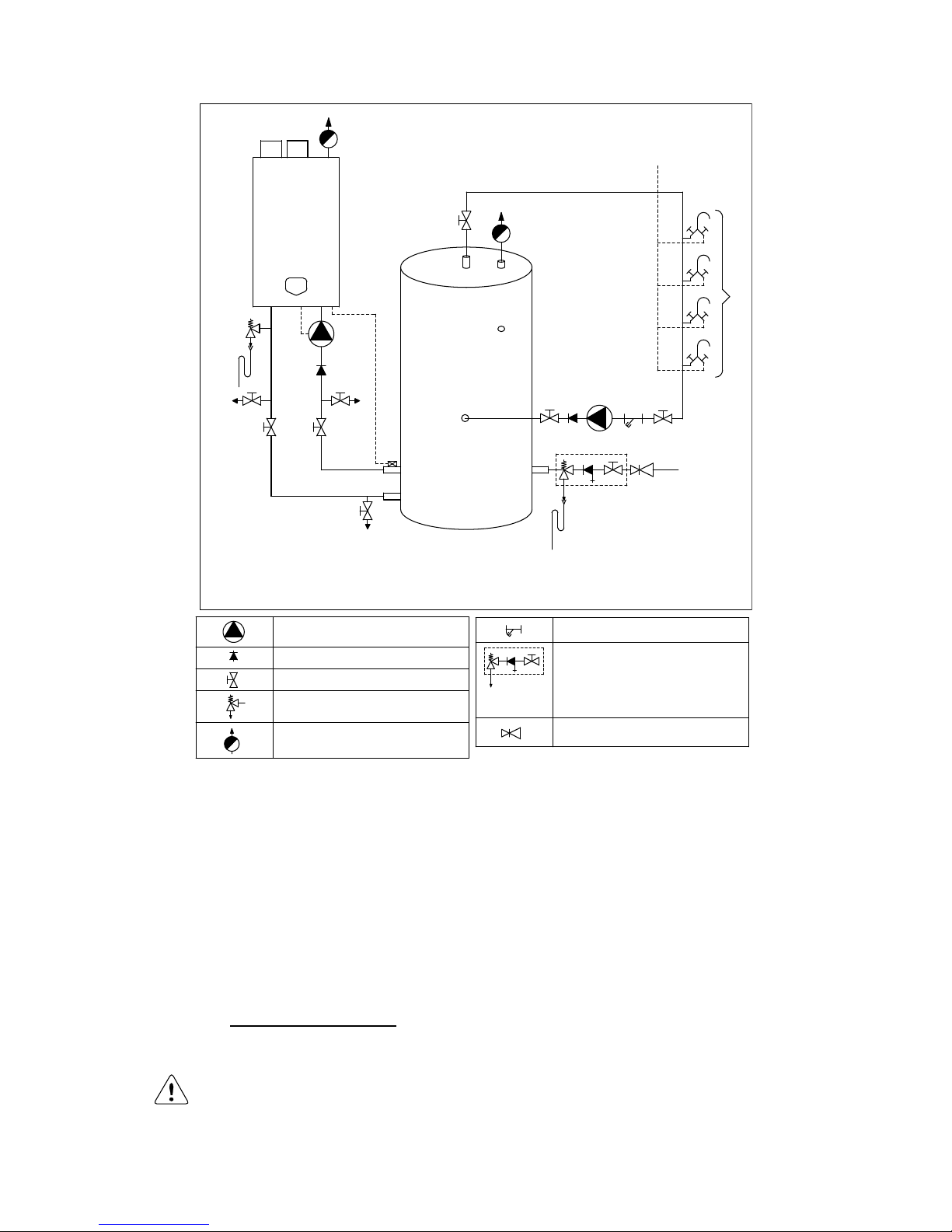
The S-WG water heater and tank should be installed by a skilled installer according to all applicable standards
and regulations for tap water installations. Use the next scheme as guideline. When multiple water heaters and
tanks are applied, every combination has to be equipped with its own safety valve.
Scheme on next page
E09.012.246 Manual S-WG
9
A) Cold water inlet
B) Hot water circulation flow
C) Circulation flow return
1) Pressure relief valve (mandatory in case service water pressure is too high)
2) Inlet combination with valve (mandatory)
3) Apply filter if necessary (recommended)
4) A suitable safety valve must be mounted near the water heater (mandatory)
This safety valve may never be isolated from the water heater by means of a ball valve
5) Mount remote pipe sensor as close as possible to the tank
6) Drain valve (recommended)
7) Hot and cold water mixers
SAFETY COMPONENTS
NB! The picture shows an example of a functional installation. The safety components as
shown in the picture are NOT necessarily conform the applicable standards and regulations.
ALWAYS have the installation installed by a skilled installer. Safety must be added according to all applicable standards and regulations.
1
2
3
A
B
C
4
7
A
5
6
6
6
PUMP
NON RETURN VALVE
VALVE
SAFETY VALVE
AUTOMATIC VENT
FILTER
INLET COMBINATION
- Overflow
- Controllable return valve
- Valve
PRESSURE REGULATING VALVE

E09.012.246 Manual S-WG
10
2 TECHNICAL DATA S-WG WATER HEATERS
GENERAL
Product Identification number CE 0063 BR3190
Classification
II2H3P
Gas Appliance Type
B23; B23P; C13X, C23X, C33X, C43X, C53X, C63X, C83X
Type water heater
S-WG80
S-WG100
S-WG120
S-WG150
S-WG180
Dimensions (h x w x d)
mm
842 x 476 x 486
898 x 476 x 677
Water content est.
Litre
5.0
6.5
8.3
10.4
12.9
Weight dry
kg
68
73
78
87
96
In- and outlet water connection union
inch
1½ 2 2 2 2
Gas connection
inch
R ¾
R ¾
R ¾
R 1
R 1
Flue duct flue/air inlet
mm
80/125
100/150
100/150
100/150
100/150
Parallel connection
mm
80-80
100-100
100-100
130-130
130-130
DOMESTIC HOT WATER
Nominal input min./max. (Net)
kW
14.6 - 74.3
17.2 - 92.2
26.0 - 111
34.0 - 138
45.0 - 166
Nominal input min./max. (gross) (G20 G25)
kW
16.2 - 82.5
19.1 - 102
28.9 - 123
37.8 - 153
50.0 - 184
Nominal input min./max. (gross) (G31)
kW
15.9 - 80.8
18.7 - 100
28.3 - 121
37.0 - 150
48.9 - 180
Nominal input min./max. (gross) (G30)
kW
15.8 - 80.2
18.6 – 99.7
34.7 - 120
36.8 - 150
48.8 - 180
Nom. output 80/60 at 100%
kW
14.0 - 71.2
16.5 - 88.4
24.7 - 106
32.6 - 132
43.3 - 180
Nom. output 50/30 at 100%
kW
15.2 - 77.5
18.0 - 96.2
27.2 - 116
35.5 - 144
47.3 - 160
Nom. output 37/30 at 30%
kW
15.7 - 80.1
18.6 - 99.5
28.1 - 120
36.7 - 149
48.5 - 175
Efficiency 40/30ºC DIN 4702-8
%
up to 110.6 % within the S-WG range
GAS CONSUMPTION [EN437]
Natural gas G25 min - max
m³st/h
1.80 - 9.14
2.12 - 11.35
3.20 - 13.66
4.18 - 16.98
5.54 - 20.43
Natural gas G20 min - max
m³st/h
1.54 - 7.86
1.82 - 9.76
2.75 - 11.75
3.60 - 14.60
4.76 - 17.57
Propane gas G31 min - max
m³st/h
0.60 - 3.04
0.70 - 3.77
1.06 - 4.54
1.39 - 5.65
1.84 - 6.79
Butane gas G30 min - max 1 (B/P)
m³st/h
0.45 - 2.29
0.53 - 2.85
0.99 - 3.44
1.05 - 4.28
1.40 - 5.15
Gas supply pressure nom. G25 2
mbar
25
Gas supply pressure nom. G20 2
mbar
20
Gas supply pressure nom. G31 2
mbar
30/37
Gas supply pressure nom. G30 2
mbar
50
EMISSION
CO2 flue gas G25/G20 min - max 3
%
8.7 - 9.0
8.7 - 9.0
8.7 - 9.0
8.7 - 9.0
8.7 - 9.0
CO2 flue gas G31 min - max 3
%
9.3 - 10.3
9.3 - 10.3
9.3 - 10.3
9.3 - 10.4
9.3 - 10.5
CO2 flue gas G30 min - max 3
%
9.3 - 10.4
9.3 - 10.4
9.3 - 10.4
9.3 - 10.5
9.3 - 10.6
NOx emission at 0% O
2
max.80/60 4
ppm
32.2
32.2
37.8
32.2
34.3
NOx emission at 0% O
2
max.80/60 4
mg/kWh
57.9
57.9
67.9
57.9
61.9
NOx - class [EN483 / EN15420]
-
5
Temperature flue gas estimated
@ combustion air temp 20ºC
°C
85-95
Available pressure for the flue system 5
Pa
200
INSTALLATION
Max. water temperature
°C
75
Pressure WW-system min./max.
bar
1.0-6.0
Hydraulic resistance of the water heater at
T = 17 K between in- and outlet
Head
mWC
5.8
4.7
4.1
6.0
5.5
ELECTRIC
Power consumption
W
170
170
190
250
250
Power supply
V / Hz
230 / 50
Protection class
IPX4D
NOTES
1
Using propane G31 or butane G30, maximum fan
speed needs to be reduced (parameter P4BD).
2
Below a table is given in which the min. and max.
gas supply pressures are mentioned acc. to EN437.
p nominal
[mbar]
p min
[mbar]
p max
[mbar]
G25
25
20
30
G20
20
17
25
G31
30
25
35
37
25
45
G30
50
43
57
3
CO2 of the unit measured/set without the water heater
door in place.
4
Emissions measured during unit certification.
5
Maximum combined resistance of flue gas and air supply
piping at high fire.

E09.012.246 Manual S-WG
11
The S-WG water heater is standard set for Natural gas G20
Gases used must meet the European standard EN 437.
Water heater control includes the next programmable features:
Cascade control for up to twelve water heaters
Remote operation and heat demand indication from each water heater
Anti-Legionnaires’ disease function
0-10 VDC remote flow temperature (set point) control
0-10 VDC connection available
The water temperature can be controlled by an external 0-10 VDC signal. When a number of water heaters are
cascaded, the signal should be directed to the master only. Less than 1 Volt will switch off the water heater(s).
Time program
Time programs with three programmable periods per day are available. These time programs are activated at
the control panel and offer great flexibility in controlling the water heater’s day and night temperatures as well as
the anti-Legionella settings.
E09.012.246 Manual S-WG
12
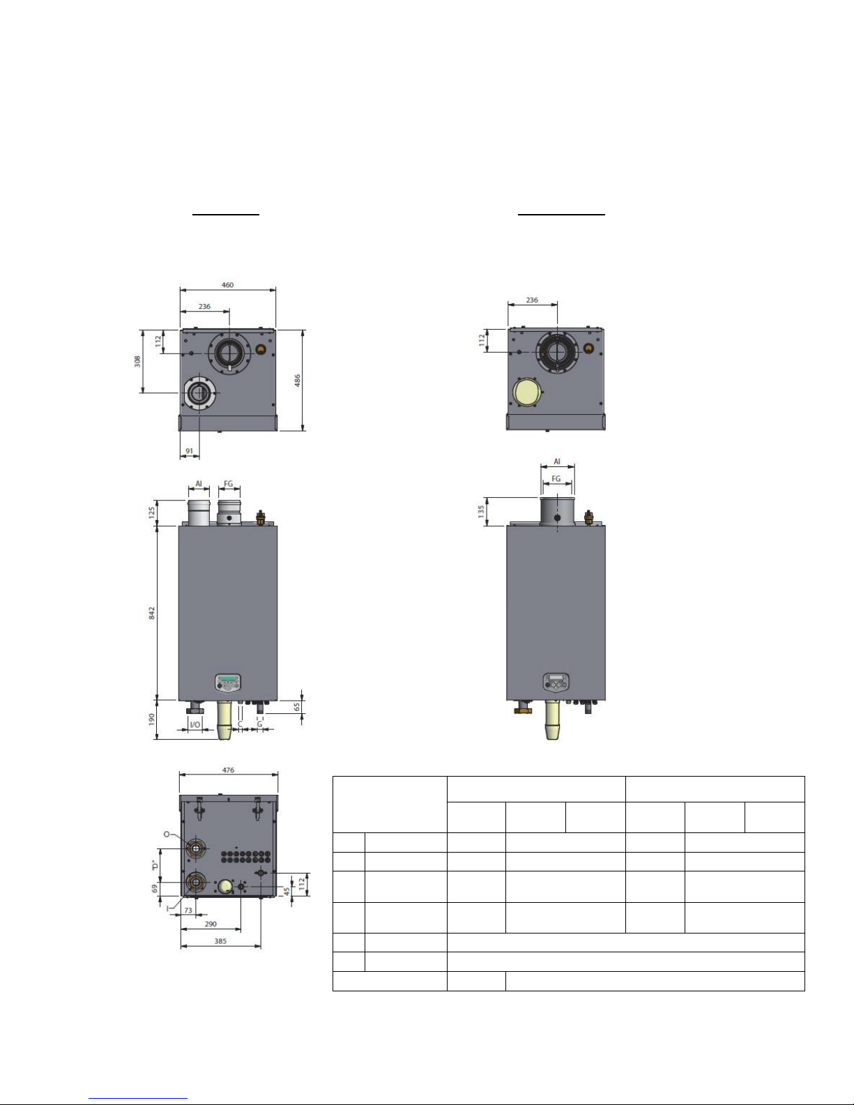
3 DIMENSIONS
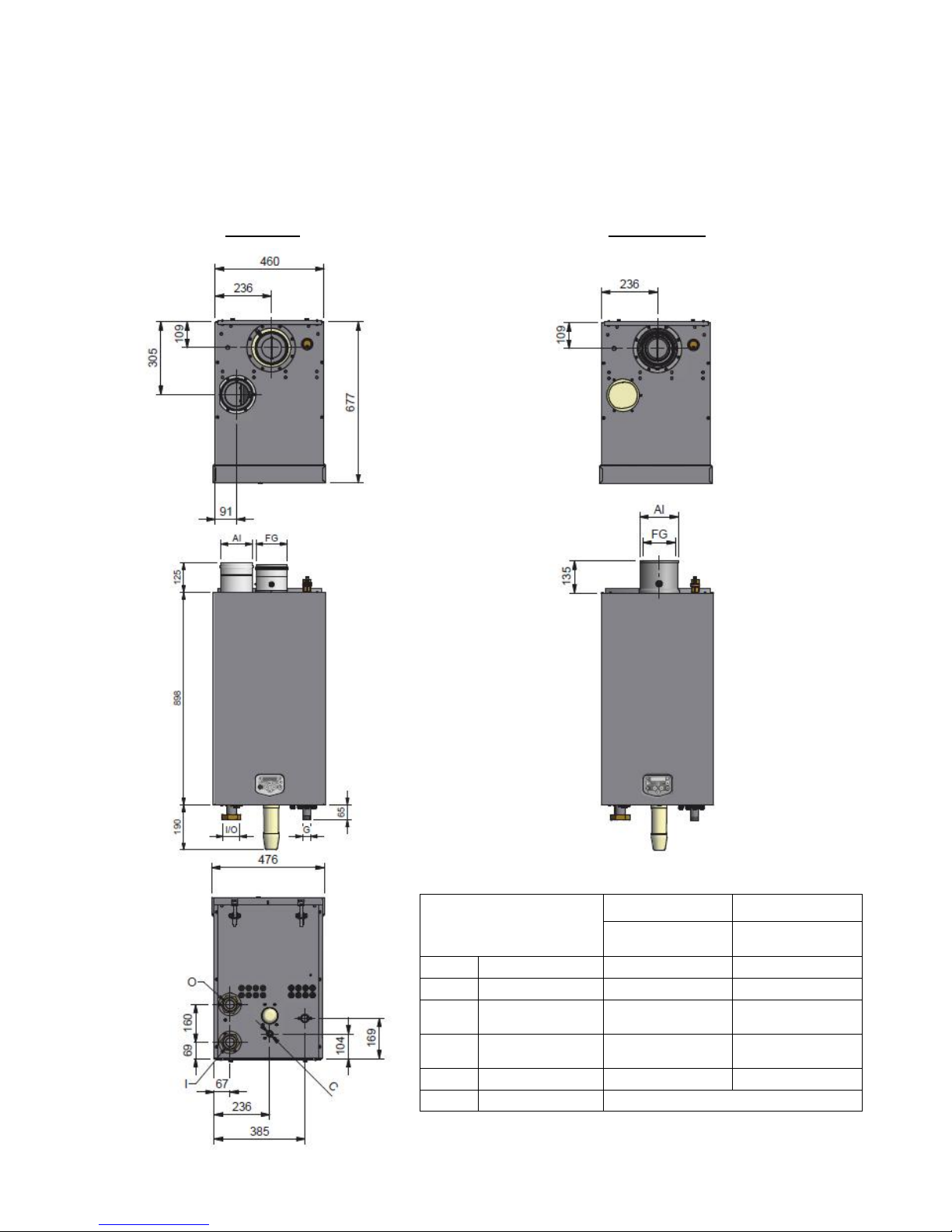
3.1 Water heaters S-WG80 – S-WG120
TWIN PIPE CONCENTRIC
Connections
(mm/ ” )
twin pipe
concentric
S-
WG80
S-
WG100
S-
WG120
S-
WG80
S-
WG100
S-
WG120
FG
flue gas
Ø80
Ø100
Ø80
Ø100
AI
air inlet
Ø80
Ø100
Ø125
Ø150
I
cold water
inlet
R 1½”
(swivel)
R 2”
(swivel)
R 1½”
(swivel)
R 2” (swivel)
O
hot water
outlet
R 1½”
(swivel)
R 2”
(swivel)
R 1½”
(swivel)
R 2” (swivel)
G
gas
R ¾” (male)
C
condensate
flexible hose Ø25/21 x 750 mm.
dimension "D"
175
160
E09.012.246 Manual S-WG
13
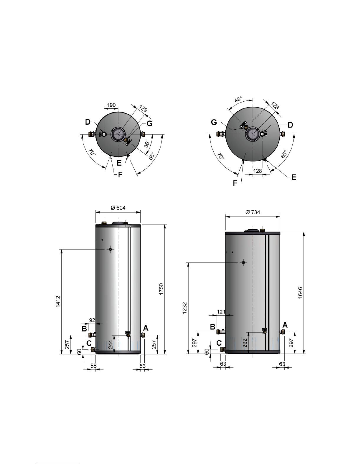
3.2 Water heaters S-WG150 and S-WG180
TWIN PIPE CONCENTRIC
Connections
(mm/ ” )
twin pipe
concentric
S-WG 150 -180
S-WG 150 -180
FG
flue gas
Ø130
Ø100
AI
air inlet
Ø130
Ø150
I
cold water inlet
Rp 2”
(swivel)
Rp 2”
(swivel)
O
hot water outlet
Rp 2”
(swivel)
Rp 2”
(swivel)
G
gas (male)
R 1”
R 1”
C
condensate
flexible hose Ø25/21 x 750 mm.
E09.012.246 Manual S-WG
14
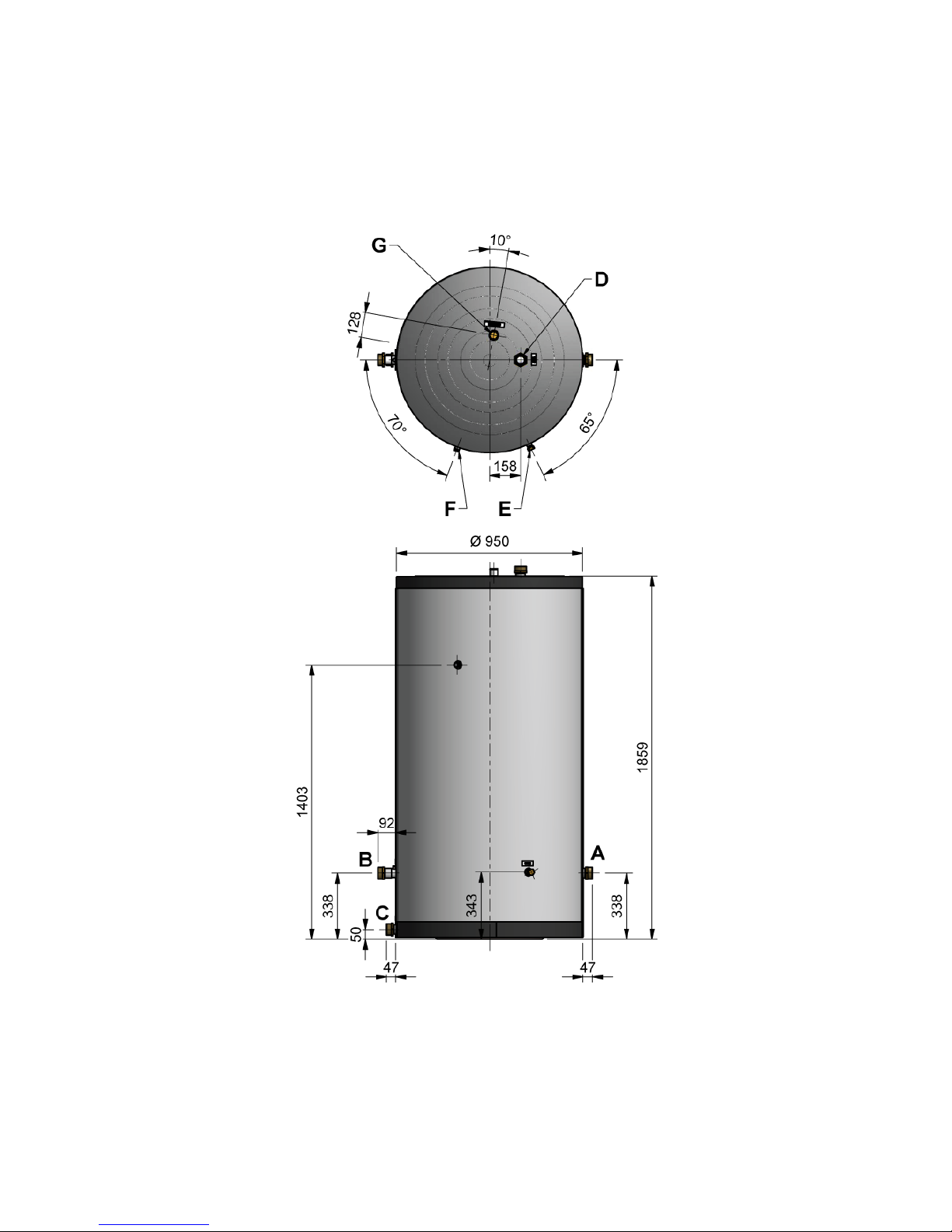
3.3 S-WG tanks
300 Ltr. 450 Ltr.
E09.012.246 Manual S-WG
15
750 Ltr.
E09.012.246 Manual S-WG
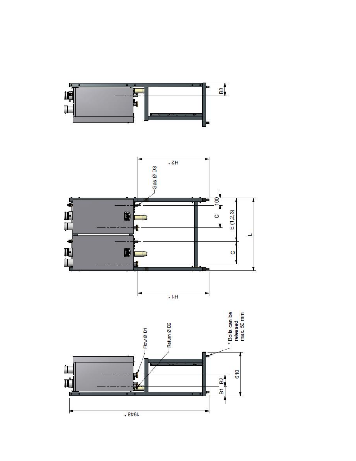
16
3.4 Cascade frames S-WG80 – S-WG180
Frames for two, three and four water heaters S-WG80 up to S-WG180

E09.012.246 Manual S-WG
17
water heaters S-WG 150 - 180
4
1980
133
160
235
317
Rp 2
Rp 2
R 1"
590
1080
1570
935
935
3
1520
133
160
235
317
Rp 2
Rp 2
R 1"
605
1110
n.v.t.
935
935
2
1015
133
160
235
317
Rp 2
Rp 2
R 1"
605
n.v.t.
n.v.t.
935
935 1 510
133
160
235
317
Rp 2
Rp 2
R 1"
n.v.t.
n.v.t.
n.v.t.
935
935
water heaters S-WG 100 - 120
4
1980
133
160
177
314
Rp 2
Rp 2
R ¾"
590
1080
1570
990
990
3
1520
133
160
177
314
Rp 2
Rp 2
R ¾"
605
1110
n.v.t.
990
990
2
1015
133
160
177
314
Rp 2
Rp 2
R ¾"
605
n.v.t.
n.v.t.
990
990
1
510
133
160
177
314
Rp 2
Rp 2
R ¾"
n.v.t.
n.v.t.
n.v.t.
990
990
water heaters S-WG 80
4
1980
133
175
177
310
Rp 1½
Rp 1½
R ¾"
590
1080
1570
990
990
3
1520
133
175
177
310
Rp 1½
Rp 1½
R ¾"
605
1110
n.v.t.
990
990
2
1015
133
175
177
310
Rp 1½
Rp 1½
R ¾"
605
n.v.t.
n.v.t.
990
990 1 510
133
175
177
310
Rp 1½
Rp 1½
R ¾"
n.v.t.
n.v.t.
n.v.t.
990
990
Number of water
heaters cascaded
L (frame)
B1 (return)
B2 (return/flow)
B3 (gas)
C (water/gas)
D1 (flow)
D2 (return)
D3 (gas)
E1 (gas 2nd water
heater)
E2 (gas 3rd water
heater)
E3 (gas 4th water
heater)
H1 (flow/return)
H2 (gas)

E09.012.246 Manual S-WG
18
4 ACCESSORIES AND UNPACKING
4.1 Accessories
Depending on the selected way of controlling the system, the following items can be supplied with the water
heater. Ask your supplier for the specifications.
Item
Part no.
1
External DHW-Tank temperature sensor 10kOhm@25°C, to be mounted on the tank
outlet to the water heater
E04.016.304
2
S-WG 80 water heater: Conversion set for concentric to parallel flue and air terminal
(80/125→80-80)
E61.001.163
3
S-WG 80 water heater: Conversion set for parallel to concentric flue-air terminal
(80-80→80/125)
E61.001.170
4
S-WG 100 - 120 water heater: Conversion set for concentric to parallel flue and air
terminal
(100/150→100-100)
E61.001.164
5
S-WG 100 - 120 water heater: Conversion set for parallel to concentric flue-air terminal (100-100→100/150)
E61.001.171
6
S-WG 150 - 180 water heater: Conversion set for concentric to parallel flue and air
terminal (100/150→130-130)
E61.001.179
7
S-WG 150 - 180 water heater: Conversion set for parallel to concentric flue-air terminal (130-130→100/150)
E61.001.180
8
Remote control DHW temperature ‘Open Therm’ RCW (modulating)
E04.016.645
9
Software set for diagnose, programming and temperature read out
E09.000.105
10
Hot water tank, stainless steel, 300 litres
E66.000.203
11
Hot water tank, stainless steel, 450 litres
E66.000.204
12
Hot water tank, stainless steel, 750 litres
E66.000.205
13
Interface cable between water heater control and computer (laptop) with USB connection
E04.016.586
4.2 Unpacking
The S-WG water heater will be supplied with the following documents and accessories:
One “Installation, Operating and Maintenance Manual”
One suspension bracket with locking plate and bolts
Attached to a connection tube:
~ One safety relief valve, to be mounted conform the applicable standards and regulations
Attached to the front of the gas valve:
~ Three spare nuts for mounting the burner plate
~ Two spare fuses for the water heater control
~ One sticker for propane or butane operation
Bottom part of the siphon, temperature sensor and connector
Two nipples with gaskets for inlet/outlet connections of the water heater
NB! A pump is separately supplied, it’s not included in the water heater supply. For pump choice, see § 9.5.
After delivery, immediately check the water heater package to see if it is complete and without any defects. Re-
port any imperfections immediately to your supplier.
E09.012.246 Manual S-WG
19
5 INSTALLATION OF THE S-WG
5.1 General notes
At every side of the water heater at least 50 mm of clearance should be applied to walls or wall units, 350 mm
above the top side of the water heater and 250 mm from the bottom of the water heater.
The installation area/room must have the following provisions:
230 V - 50 Hz power source socket with earth connection.
Open connection to the sewer system for draining condensing water:
Note:
The wall used for mounting the water heater must be able to hold the weight of the water heater. If this is not the
case it is recommended to mount the water heater on a (cascade) frame.
Other considerations related to the water heater location:
The ventilation of the plant room must meet all applicable standards and regulations, regardless of the
selected supply of fresh air to the water heater location.
Both the air supply and the flue gas tubes must be connected to the outside wall and/or the outside roof.
The installation area must be dry and frost-free.
The water heater has a built-in fan that will generate noise, depending on the total heat demand. The wa-
ter heater location should minimise any disturbance this might cause. Preferably it is suggested to mount
the water heater on a brick wall.
There must be sufficient lighting available in the plant room to work safely on the water heater.
Remind the positioning of electrical components in relation to the temperature sensitivity.
Make sure there is an open connection with the sewer to drain the condensate. This connection should
be lower than the condensate drain level of the water heater.
The water heater must be positioned and installed by a certified installer in accordance with all applicable standards and regulations. Commissioning of the water heater must be done by a skilled service/commissioning
engineer.
E09.012.246 Manual S-WG
20
5.2 Mounting the water heater and tank
5.2.1 WATER HEATER MOUNTING
Before mounting and installing the water heater the following connections should be considered:
Flue gas system and the flue gas pipe connections
Air supply system and connections
‘Cold in’ and ‘hot out’ pipe connection
Condensate and pressure relief valve drainage
Power supply (preferably the power connection is positioned above the water heater)
All lines/piping must be mounted free of tension. The weight of all the installation components should be
supported separately from the water heater so there will be no standing force on the connections.
This might influence the mounting position of the water heater.
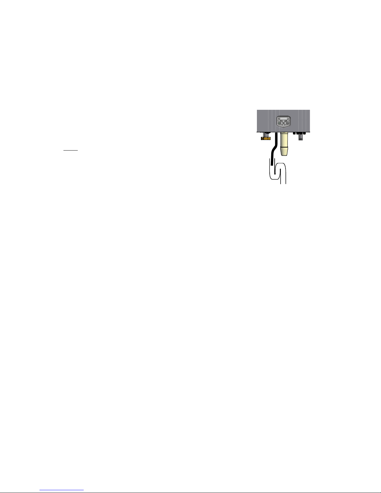
Determine the position of the flow and return pipes by using the included suspension bracket or a suspension
frame (when supplied).
While marking the holes, ensure that the suspension bracket or frame is perpendicular and the water heater
does not lean forward. If necessary adjust the position with the adjusting bolts at the lower rear side of the back
panel (see drawing). When the adjusting bolts aren’t sufficient, fill the gap behind the bolts to get the water
heater in position. The exact water heater position lies between the water heater hanging level and hanging
slightly backwards.
The water heater should not lean forward in the mounted position.
Lock the suspension bracket with the security cover before making any other connections to the water heater.
This security cover will prevent the water heater from falling off the bracket. Don't use excessive force during the
mounting of the water heater connections.
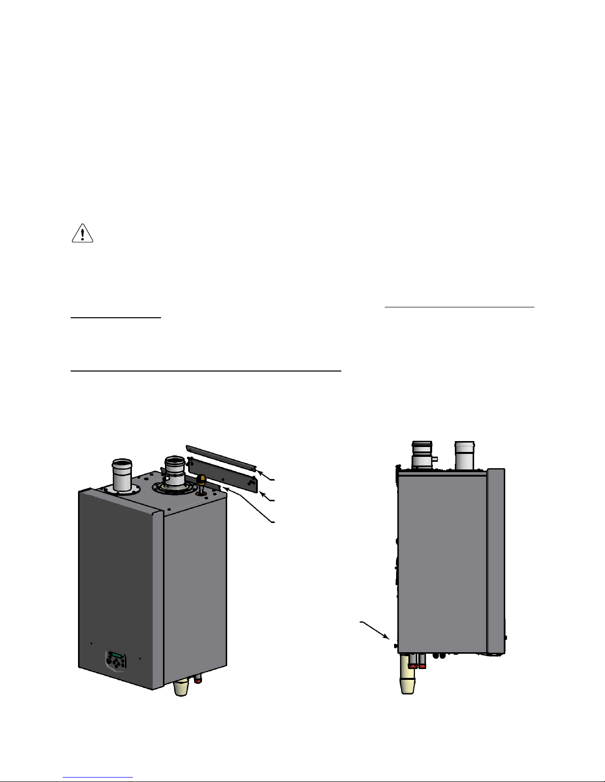
3. Lock water heater with
locking plate and two bolts
1. Attach mounting bracket to wall
with inclined side facing upwards
2. Suspend water heater with suspen-
sion bracket on mounting bracket
4. Level water heater using
adjusting bolts
E09.012.246 Manual S-WG
21
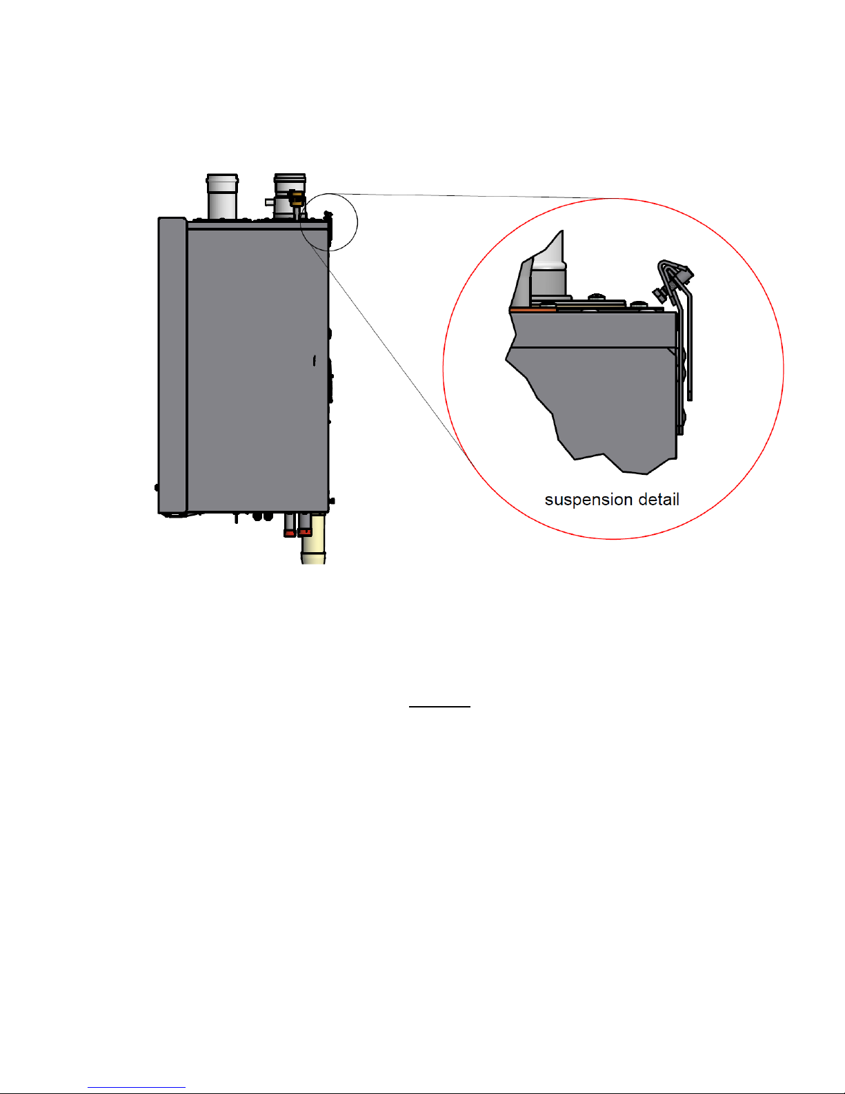
Detailed drawing of the water heater mounting and the fixation of the locking plate.
5.2.2 TANK POSITIONING
The tank can be placed at will* on a stable floor, but not too far from the water heater(s). See § 9.4.3, ‘Interconnecting pipes – equivalent length’, on page 50.
* NB! This floor must be able to hold the weight of the water filled tank(s).

E09.012.246 Manual S-WG
22
6 FLUE GAS AND AIR SUPPLY SYSTEM
6.1 General
The water heater has a positive pressure flue system. The available combined pressure drop for the inlet and
outlet system, for a single water heater, is 200 Pa for the complete water heater range. For a multiple water
heater installation, always contact the manufacturer for advice.
Notice:
Install the horizontal flue components with an angle of 3° downwards in the direction of the water heater
(roughly equal to five centimetres for every linear meter). When not installed accordingly, it may result in
condensate building-up in the flue gas tube, eventually causing component failure.
Wall flue terminals are generally used up to 80 kW. Using these terminals with larger capacities will give
unpleasant large condensate clouds.
When using a wall terminal, there is the possible risk of ice building-up on surrounding parts/structures,
because the condensate will freeze. This risk should be taken into account during the design phase of the
DHW installation.
Note:
Because the flue gases can have a relatively low temperature, the water heater needs to have a high efficiency
approved stainless steel or plastic flue system. These materials should be usable for the applied pressure in the
flue gas system, be condensate proof and have a temperature class of T-120.
6.2 Air supply
When an air supply duct is connected from the outside of the building to the water heater, the water heater will
operate as a room-independent water heater (closed water heater).
The air supply duct can be made of:
PVC / PPs
Thin-walled aluminium
Stainless steel
NOTICE: When the supply duct will be placed in a plant room with moist air (for example: greenhouses), a sufficiently insulated duct must be used to prevent the possible condensation at the outside of the duct. It is not possible to insulate the internal air pipes of the water heater and therefore condensation at the internal air canals
must be prevented. The air supply duct needs to be protected against rain falling on top of the roof, so no rain
water will enter the water heater.
6.3 Flue terminal
Never use aluminium (containing) flue gas materials for this water heater
The flue terminal duct can be made of:
Stainless steel with T-120 gaskets
PPs temperature class T-120
E09.012.246 Manual S-WG
23
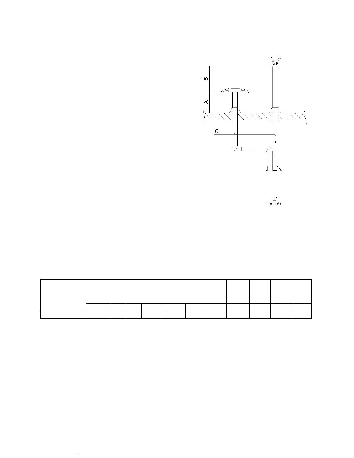
Height A
This is the height of the air inlet. A rain hood should prevent rainwater entering the air supply system.
When the inlet and outlet are mounted on a flat roof, the inlet
should be at least 60 cm above the roof surface and at least
30 cm above the maximum snow level.
Example 1:
When the maximum snow level on the roof surface is 45 cm
then the air inlet should be at 45+30=75 cm. 75 cm is more
than the minimum 60 so the height will be 75 cm.
Example 2:
When the maximum snow level on the roof surface is 15 cm
then the air inlet should be at 15+30=45 cm. 45 cm is less
than the minimum 60 cm so the height will be 60 cm.
Height B
This is the height of the flue outlet related to the air inlet.
The flue gas outlet should be at least 70 cm above the air inlet. It is advised to be equipped with a conical outlet.
A single flue outlet should be situated at least 100 cm
above the roof surface.
Distance C
The horizontal distance between the flue gas pipe and air
inlet pipe at roof level.
This distance should be at least 70 cm.
6.4 Flue system classification B23P
Overpressure flue gas systems
For classification B23P and for overpressure flue gas systems the minimum requirements of the flue gas material for S-WG appliances can be determined in a designation string according to the EN1443 (see table).
CE string flue gas
material (B23P)
European
standard
Temperature
class
Pressure
class
Resistance to
condensate
Corrosion
resistance
class
Metal:
liner
specifications
Soot fire
resistance
class
Distance
to combustible material
Plastics:
location
Plastics:
fire behaviour
Plastics:
enclosure
min. requirement PPs
EN 14471
T120
P1 W 1 O
30
I or E
C/E
L
min. requirement StS
EN 1856-1
T120
P1 W 1
L20040 O 40
A few examples of flue gas material suitable for S-WG water heaters:
CE String for Plastic PPs: EN14471 T120 P1 W 2 O(30) I C/E L
CE String for Stainless Steel: EN1856-1 T250 P1 W V2-L50040 )(50)
When selecting flue gas systems, be aware that the minimum requirements are met. So only select flue gas
materials having the same or better properties than this table.
6.5 Flue system classification C63
In general, appliances are certified with their own flue gas material. If a water heater is C63 certified, no specific
type flue gas material has been certified in combination with the water heater. In this case the flue gas material
does not need to be certified in combination with the water heater but should be fit for purpose, and comply with
the applicable European standards. It must be able to handle the condensate forming and transport, overpressure and must have a minimum temperature class of T120.

E09.012.246 Manual S-WG
24
6.6 Combustion air quality
Combustion air must be free of contaminants. For example: chlorine, ammonia and/or alkali agents, dust, sand
and pollen. Remind that installing a water heater near a swimming pool, a washing machine, laundry or chemical
plants does expose combustion air to these contaminants.
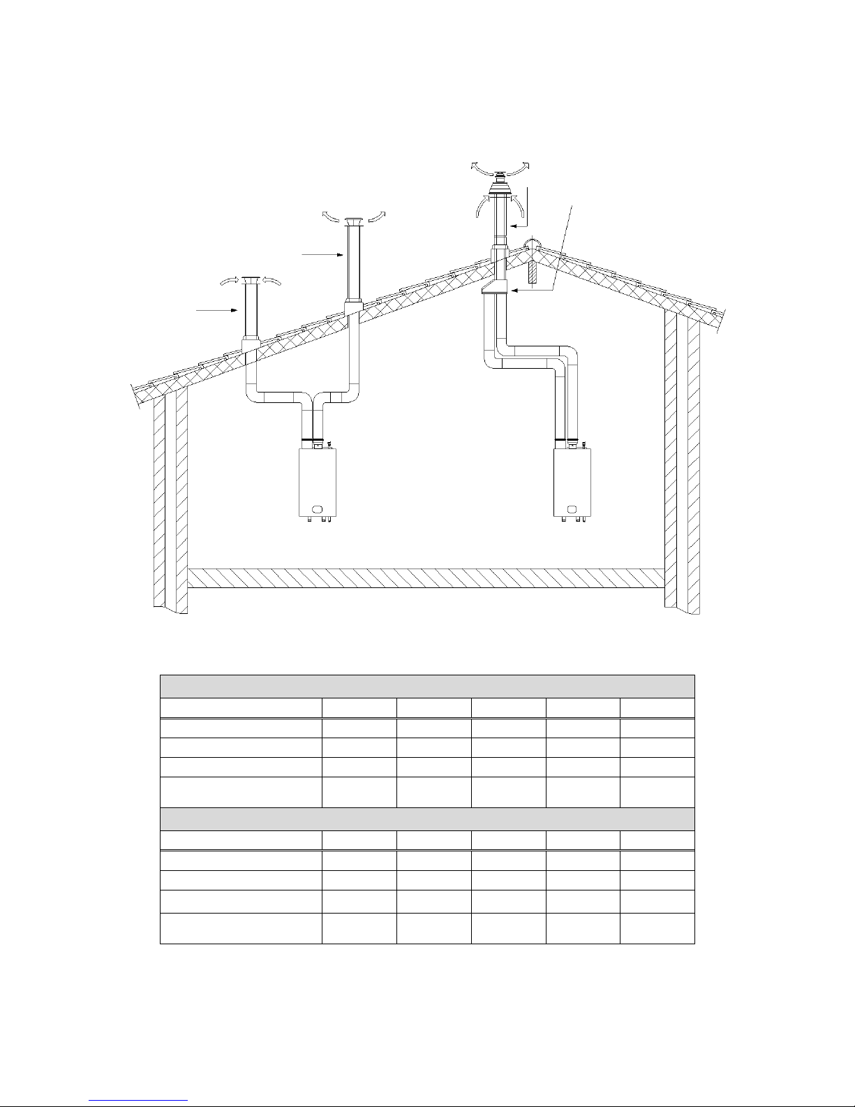
6.7 Flue gas & air inlet calculation examples (next pages)
For several flue gas & air inlet combinations the maximum length of the pipes will be calculated using the given
table:
A: Twin pipe system with separate pipes for flue gas and air supply
B: Twin pipe system with separate pipes and concentric roof terminal
C: Single pipe for flue gas outlet only (air supply from plant room)
E09.012.246 Manual S-WG
25
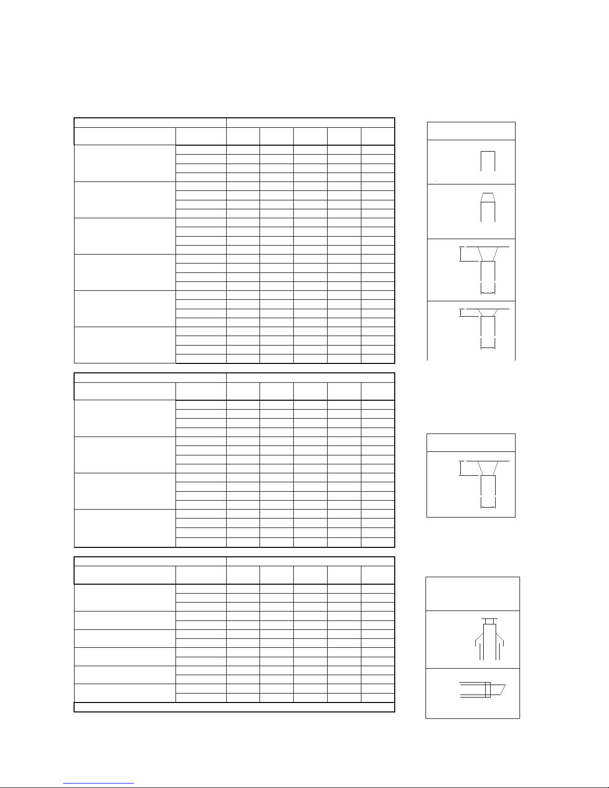
Flue gas and air supply resistance table
NOTICE: This table can only be used for a single flue/air system for one water heater. Do NOT use this table for
common flue/air systems with cascaded water heaters.
FLUE GAS PIPING
RESISTANCE [Pa]
Ø [mm] *
S-
WG80
S-
WG100
S-
WG120
S-
WG150
S-
WG180
straight tube/m
80
8.0 - - - -
100
3.5
4.0
6.5 - -
130
0.8
1.2
1.8
3.8
6.0
150
-
0.5
0.8
1.7
3.0
45° bend
80
4.0 - - - -
100
1.7
2.0
3.2 - -
130
0.4
0.6
0.8
1.9
3.0
150
-
0.2
0.4
0.8
1.5
90° bend
80
8.0 - - - -
100
3.5
4.0
6.5 - -
130
0.8
1.2
1.8
3.8
6.0
150
-
0.5
0.7
1.7
3
Flue outlet zeta=0.05
80
1.2 - - - -
100
0.5
0.8
1.1 - -
130
0.18
0.3
0.4
0.6
0.9
150
-
0.15
0.2
0.35
0.5
Flue outlet zeta=1.0
80
24 - - - -
100
9.8
15.2
22.1 - -
130
3.5
5.3
7.8
12
17.3
150
-
3.0
4.4
6.8
9.8
Flue outlet zeta=1.5
80
36 - - - -
100
14.8
22.8
33.2 - -
130
5.2
8.0
11.6
18
26
150
-
4.5
6.6
10.2
14.7
AIR SUPPLY PIPING
RESISTANCE [Pa]
Ø [mm] *
S-
WG80
S-
WG100
S-
WG120
S-
WG150
S-
WG180
straight tube/m
80
7.5 - - - -
100
3.0
3.5
4.0 - -
130
0.75
0.8
1.1
1.2
2.0
150
-
0.3
0.4
0.6
1.2
45° bend
80
3.5 - - - -
100
1.5
1.7 2 -
-
130
0.4
0.4
0.5
0.6
1.0
150
-
0.15
0.2
0.3
0.6
90° bend
80
7.0 - - - -
100
3.0
3.5
4.0 - -
130
0.7
0.8
1.1
1.2
2.0
150
-
0.3
0.4
0.6
1.2
Air inlet zeta=1.0
80
18.1 - - - -
100
7.4
11.4
16.7 - -
130
2.6
4.0
5.8
9.1
13.1
150
-
2.3
3.3
5.1
7.4
CONCENTRIC PARTS
RESISTANCE [Pa]
Ø [mm] *
S-
WG80
S-
WG100
S-
WG120
S-
WG150
S-
WG180
roof terminal
80/125
61 - - - -
100/150
-
39
45
69
86
130/200
- - -
15
23
outside wall terminal
80/125
22 - - - -
100/150
-
19
24
40
48
straight tube/m
80/125
12 - - - -
100/150
-
8.0
10
14
16
45° bend conc.
80/125
7 - - - -
100/150
-
8.0
9.0
14
16
90° bend conc.
80/125
13 - - - -
100/150
-
11
13
22
28
conc./par. adaptor
80/125
14 - - - -
100/150
-
16
22
40
56
* Do not reduce pipe diameters relative to water heater connections
Roof
FLUE GAS OUTLET
AIR INLET
CONCENTRIC
Wall
H
D
H/D=1,0
zeta=1,0
AIR INLET
H
D
H/D=0,5
zeta=1,5
H
D
H/D=1,0
zeta=1,0
conical outlet
zeta=0,05
FLUE GAS OUTLET
open outlet
zeta=0
zeta = 0.0
open outlet
zeta = 0.05
conical outlet
H/D = 1.0
zeta = 1.0
H/D = 0.5
zeta = 1.5
H/D = 1.0
zeta = 1.0
Roof
Wall
FLUE GAS OUTLET
AIR INLET
CONCENTRIC
FLUE GAS OUTLET
AIR INLET
E09.012.246 Manual S-WG
26
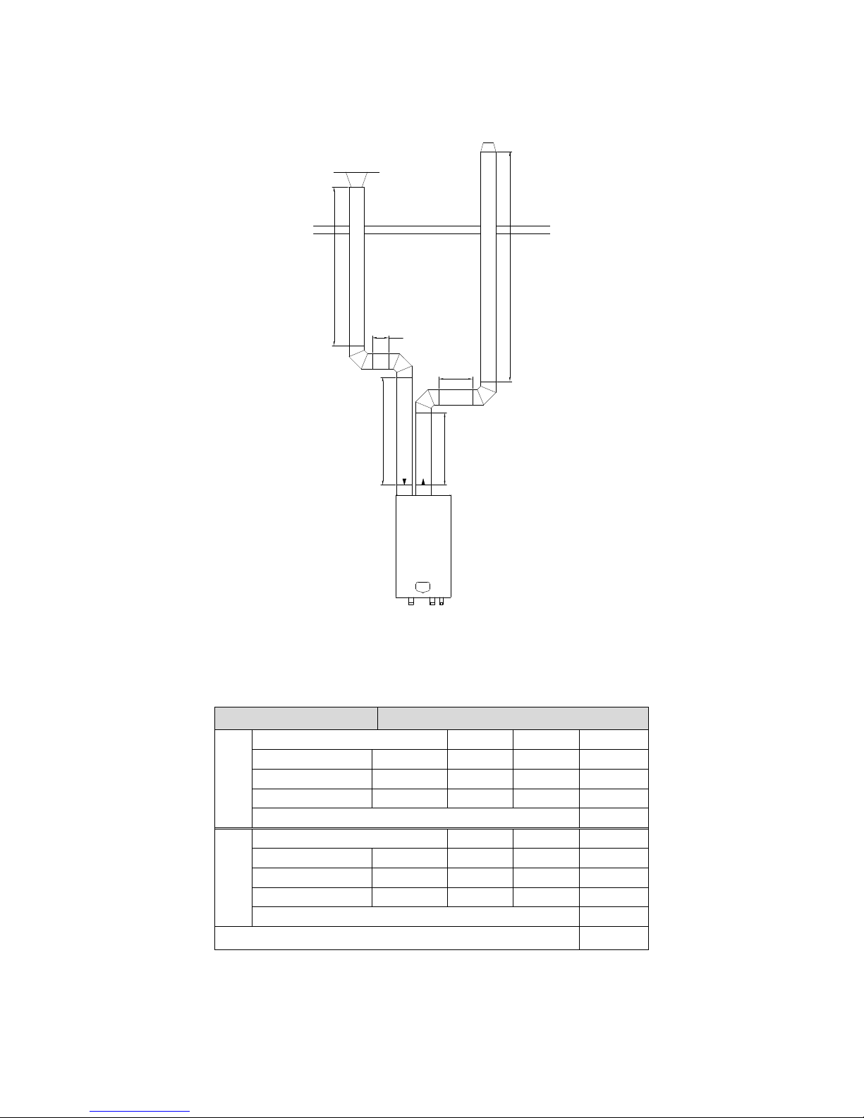
A: Twin pipe system with separate pipes for flue gas and air supply.
Example A
The total resistance is less than 200 Pa. This flue gas/air supply system is functional.
180
4m
2m
2m
2m
2m
5m
Water heater type:
S-WG 180
Flue gas
Diameter: 130 mm.
Number
Pa
Pa total
Straight tube m¹
total 9 6
54
Bend
90° 2 6
12
Flue outlet
conical
1
0.9
0.9
Total resistance flue gas outlet:
66.9
Air supply
Diameter: 130 mm.
Number
Pa
Pa total
Straight tube m¹
total 8 2
16
Bend
90° 2 2
4
Air inlet
H/D = 1.0
1
13.1
13.1
Total resistance air supply:
33.1
Total resistance flue gas outlet and air supply:
100 Pa
E09.012.246 Manual S-WG
27
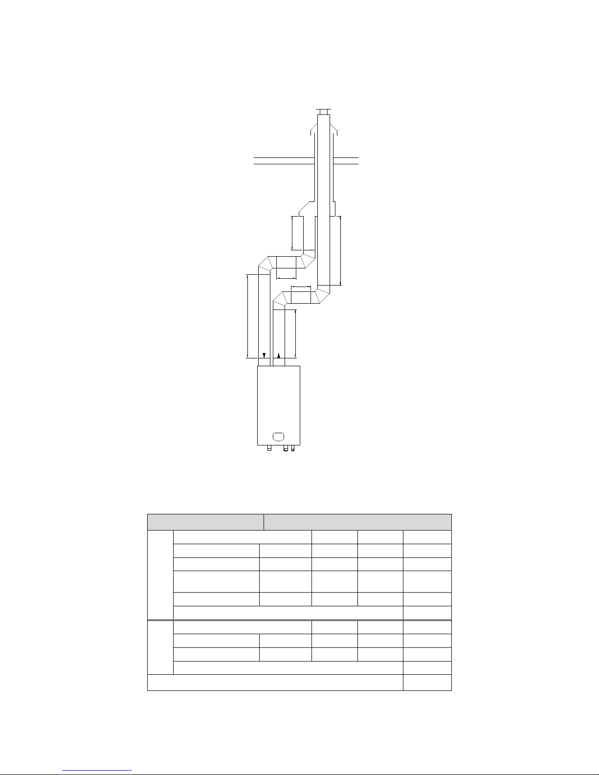
B: Twin pipe system with separate pipes and concentric roof terminal.
Example B
The total resistance is less than 200 Pa. This flue gas/air supply system is functional.
120
2m
2m
2m
2m
2m
2m
Water heater type:
S-WG 120
Flue gas
Diameter: 100 mm.
Number
Pa
Pa total
Straight tube m¹
total
6
6.5
39
Bend
90° 2 6.5
13
Roof terminal
concentric
150/100
1
45
45
Adaptor conc./par.
150/100
1
22
22
Total resistance flue gas outlet:
119
Air sup-
ply
Diameter: 100 mm.
Number
Pa
Pa total
Straight tube m¹
total 6 4
24
Bend
90° 2 4
8
Total resistance air supply:
32
Total resistance flue gas outlet and air supply:
151 Pa
E09.012.246 Manual S-WG
28
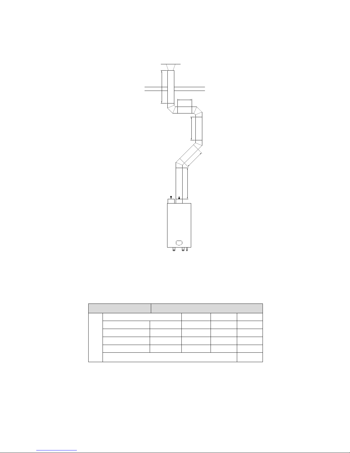
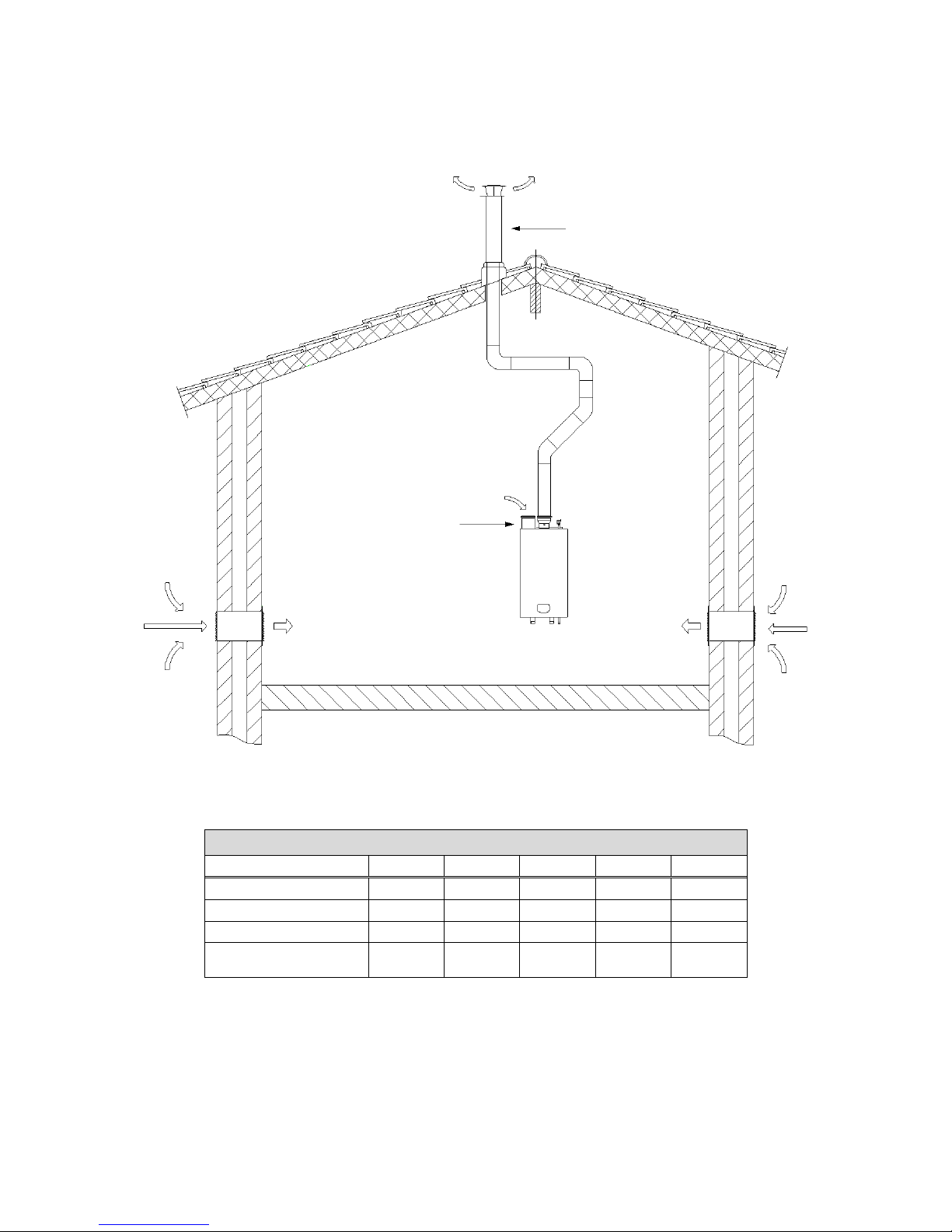
C: Single pipe for flue gas outlet only (air supply from plant room).
Example C
The total resistance is less than 200 Pa. This flue gas/air supply system is functional.
100
4m
2m
3m
2
m
2m
Water heater type:
S-WG 100
Flue gas
Diameter: 100 mm.
Number
Pa
Pa total
Straight tube m¹
total
13 4 52
Bend
90° 2 4
8
Bend
45° 2 2
4
Flue outlet
H/D = 1.0
1
15.2
15.2
Total resistance flue gas outlet:
79.2
E09.012.246 Manual S-WG
29
Twin pipe system: flue gas and air supply positions.
Example A
water heater type
S-WG80
S-WG100
S-WG120
S-WG150
S-WG180
Diameter air inlet
80
100
100
130
130
Diameter flue outlet
80
100
100
130
130
Diameter roof terminals
80
100
100
130
130
Maximum pipe length
(inlet + outlet together)
18.0
31.5
24.0
44.5
30.0
Example B
water heater type
S-WG80
S-WG100
S-WG120
S-WG150
S-WG180
Diameter air inlet
80
100
100
130
130
Diameter flue outlet
80
100
100
130
130
Concentric roof terminal
80/125
100/150
100/150
130/200
130/200
Maximum pipe length
(inlet + outlet together)
12.0
23.0
16.5
40.5
25.5
Concentric roof terminal
Air inlet
Flue outlet
Example A
Example B
concentric/parallel adaptor
E09.012.246 Manual S-WG
30
Single pipe system: flue gas positions:
Example C
water heater type
S-WG80
S-WG100
S-WG120
S-WG150
S-WG180
Diameter air inlet
80
100
100
130
130
Diameter flue outlet
80
100
100
130
130
Diam. roof terminal
80
100
100
130
130
Maximum pipe length
(total outlet length)
21.5
46.5
27.5
49.5
30.0
Example C
Vented area
Air inlet
Flue outlet
E09.012.246 Manual S-WG
31
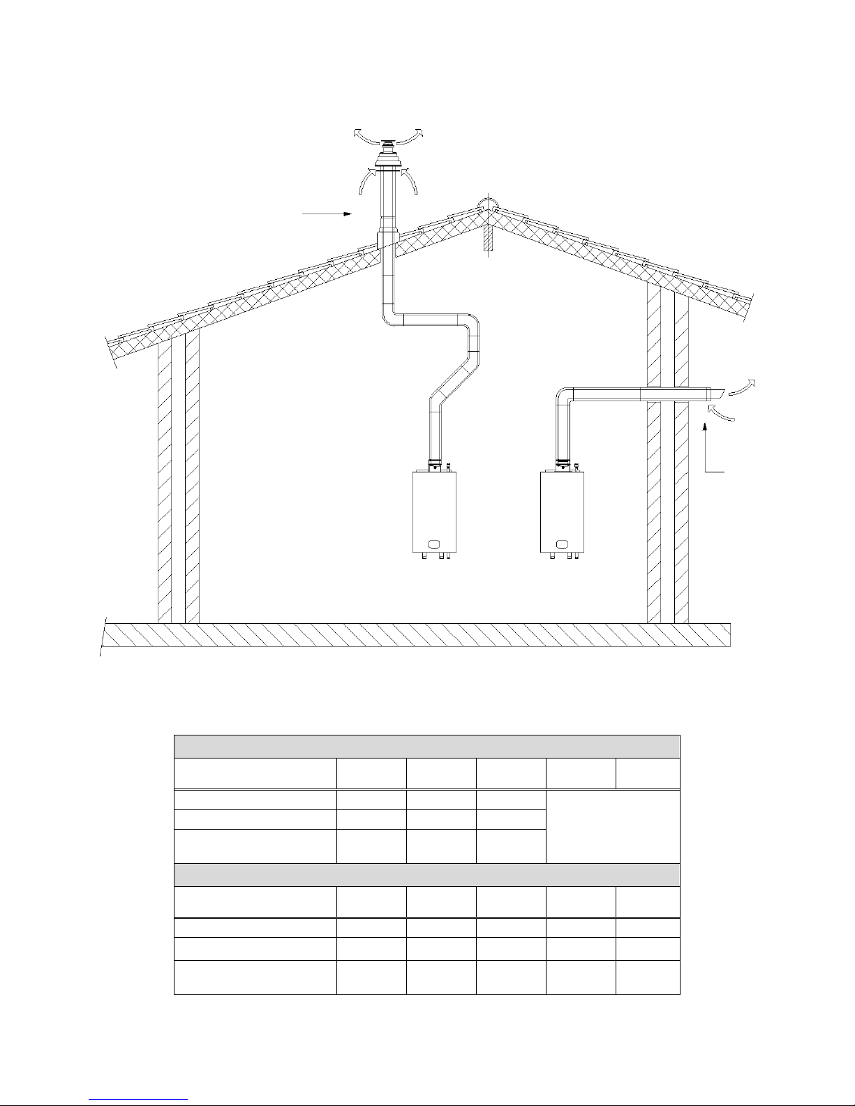
Concentric pipe system: flue gas positions:
Example D
water heater type
S-WG80
S-WG100
S-WG120
S-WG150
S-
WG180
Diameter concentric pipe
80/125
100/150
100/150
NOT
RECOMMENDED
(choose B, C or E)
Concentric roof terminal
80/125
100/150
100/150
Maximum pipe length
7.0
14.5
10.0
Example E
water heater type
S-WG80
S-WG100
S-WG120
S-WG150
S-
WG180
Diameter concentric pipe
80/125
100/150
100/150
100/150
100/150
Concentric wall terminal
80/125
100/150
100/150
100/150
100/150
Maximum pipe length
12.5
20.0
15.0
8.5
6.5
Concentric roof terminal
Concentric
wall
terminal
Example D
Example E
 Loading...