

Strebel S-WG 100, S-WG 80, S-WG 120, S-WG 150, S-WG 180 Installation, Operating And Maintenance Manual
Page 1
STREBEL
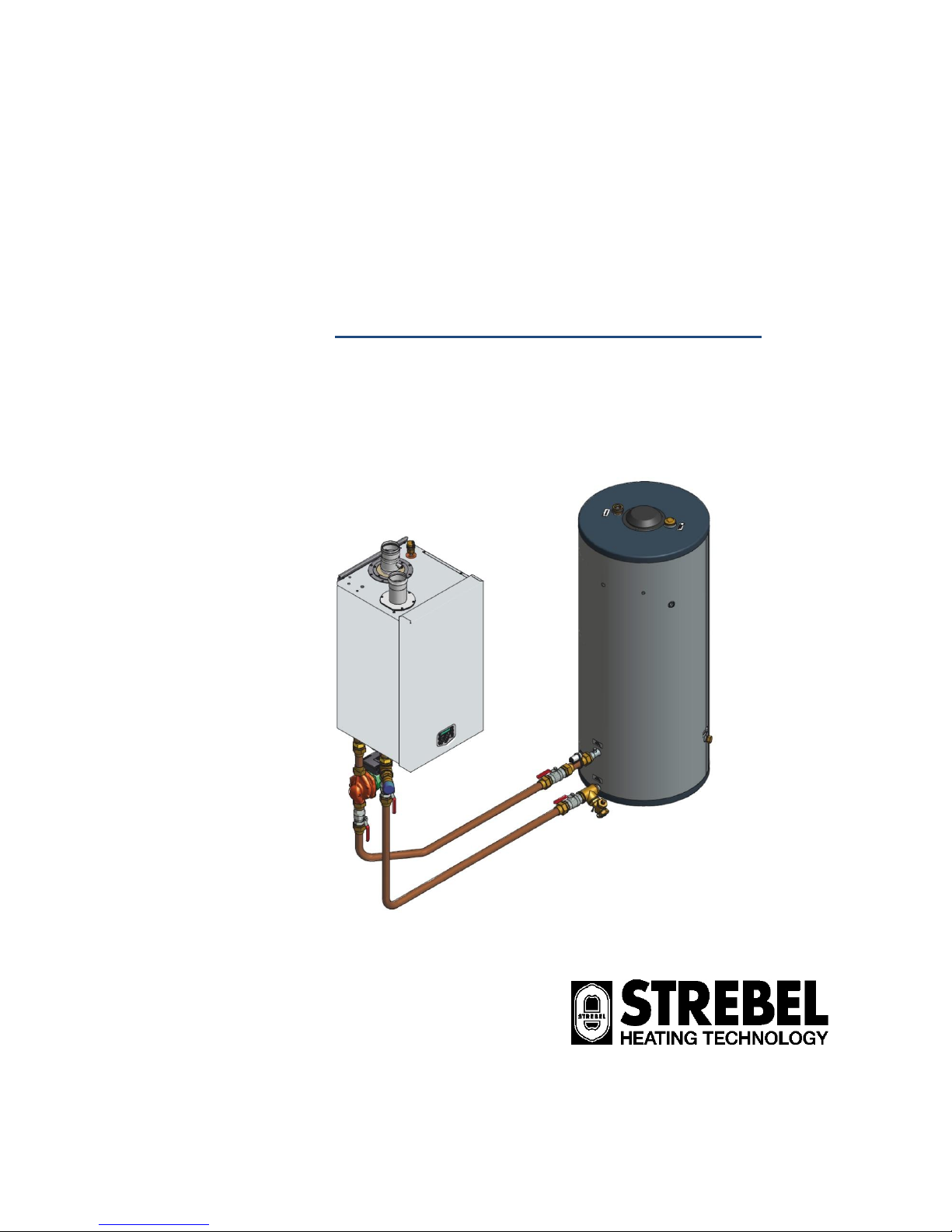
S-WG
80 - 100 - 120 - 150 - 180
Wall hung high efficiency water heater
Installation, Operating and Maintenance Manual
2015-05-06 v2.1
Page 2

E09.012.246 Manual S-WG
3
TABLE OF CONTENTS
INTRODUCTION ……………………….………………………..........................................................................................................5
1 SAFETY GUIDELINES ................................................................................................................................................................. 5
1.1 GENERAL ...................................................................................................................................................................... 5
1.2 IMPORTANT TECHNICAL WARNINGS AND GUIDELINES ........................................................................................................ 6
2 TECHNICAL DATA S-WG WATER HEATERS .......................................................................................................................... 10
3 DIMENSIONS ............................................................................................................................................................................. 12
3.1 WATER HEATERS S-WG80 – S-WG120 ........................................................................................................................ 12
3.2 WATER HEATERS S-WG150 AND S-WG180.................................................................................................................. 13
3.3 S-WG TANKS ............................................................................................................................................................... 14
3.4 CASCADE FRAMES S-WG80 – S-WG180 ...................................................................................................................... 16
4 ACCESSORIES AND UNPACKING ........................................................................................................................................... 18
4.1 ACCESSORIES ............................................................................................................................................................. 18
4.2 UNPACKING ................................................................................................................................................................. 18
5 INSTALLATION OF THE S-WG ................................................................................................................................................. 19
5.1 GENERAL NOTES ................................................................................................ ................................ .......................... 19
5.2 MOUNTING THE WATER HEATER AND TANK .................................................................................................................... 20
5.2.1 Water heater mounting ........................................................................................................................................... 20
5.2.2 Tank positioning ..................................................................................................................................................... 21
6 FLUE GAS AND AIR SUPPLY SYSTEM ................................................................................................................................... 22
6.1 GENERAL .................................................................................................................................................................... 22
6.2 AIR SUPPLY ................................................................................................................................................................. 22
6.3 FLUE TERMINAL............................................................................................................................................................ 22
6.4 FLUE SYSTEM CLASSIFICATION B23P ............................................................................................................................ 23
6.5 FLUE SYSTEM CLASSIFICATION C63 .............................................................................................................................. 23
6.6 COMBUSTION AIR QUALITY ............................................................................................................................................ 24
6.7 FLUE GAS & AIR INLET CALCULATION EXAMPLES (NEXT PAGES) ....................................................................................... 24
7 ELECTRICAL INSTALLATION .................................................................................................................................................. 32
7.1 GENERAL .................................................................................................................................................................... 32
7.2 ELECTRICAL CONNECTIONS .......................................................................................................................................... 32
7.3 SENSOR VALUES .......................................................................................................................................................... 33
7.4 ELECTRICAL SCHEMATICS ............................................................................................................................................. 34
8 THE S-WG WATER HEATER .................................................................................................................................................... 36
8.1 WATER QUALITY........................................................................................................................................................... 36
8.2 FROST PROTECTION ..................................................................................................................................................... 36
8.3 LEGIONELLA PROGRAM................................................................................................................................................. 36
8.4 FLOW MONITORING ...................................................................................................................................................... 37
8.5 WATER PRESSURE SWITCH ........................................................................................................................................... 37
9 THE S-WG SANITAIRY SYSTEM: INSTALLATION INSTRUCTIONS ...................................................................................... 38
9.1 THE S-WG SYSTEM ..................................................................................................................................................... 38
9.1.1 Stand-alone set-up ................................................................................................................................................. 38
9.1.2 Cascade set-up ...................................................................................................................................................... 39
9.1.3 Control general ....................................................................................................................................................... 41
9.1.4 Cascade control ..................................................................................................................................................... 41
9.2 WATER HEATER AND TANK: CONNECTIONS AND CONNECTION SIZES ................................................................................ 42
9.2.1 Connecting the tank to the water heater ................................................................................................................. 42
9.2.2 To connect the tank to your DHW installation ......................................................................................................... 43
9.2.3 Condensate drain connection ................................................................................................................................. 44
9.3 CASCADE SYSTEMS: ASSIGNING PIPE CODES ................................................................................................................. 45
9.3.1 Pipe codes water heater side ................................ ................................................................................................ . 45
9.3.2 Pipe codes at the tanks’ side .................................................................................................................................. 46
9.3.3 Equivalent length .................................................................................................................................................... 46
9.4 CONNECTION COMPONENT TABLES – DIAMETERS AND LENGTHS ..................................................................................... 47
9.4.1 Water manifolds ..................................................................................................................................................... 47
9.4.2 Tank headers ......................................................................................................................................................... 48
9.4.3 Interconnecting pipes – diameters and equivalent length ....................................................................................... 50
9.5 PUMP CHOICE AND PUMP CONTROL ............................................................................................................................... 51
9.5.1 Pump choice .......................................................................................................................................................... 51
9.5.2 Nominal flow per water heater type ........................................................................................................................ 52
9.5.3 Pump control .......................................................................................................................................................... 52
9.5.4 Pump: maximum electrical power ........................................................................................................................... 53
9.6 ELABORATED EXAMPLES .............................................................................................................................................. 54
9.6.1 One S-WG20 water heater with one 450-litres tank ............................................................................................... 54
9.6.2 Two S-WG100 water heaters with two 450-litres tanks .......................................................................................... 55
9.6.3 Three S-WG180 water heaters with five 750-litres tanks ........................................................................................ 56
Page 3

E09.012.246 Manual S-WG
4
10 USER INTERFACE .................................................................................................................................................................... 58
10.1 CONTROL PANEL / DISPLAY UNIT ................................................................................................................................... 58
10.2 CONTROL PANEL MENU STRUCTURE .............................................................................................................................. 59
10.3 DISPLAY DURING OPERATION ........................................................................................................................................ 60
10.4 MONITOR SCREENS ...................................................................................................................................................... 61
10.5 SERVICE FUNCTION ...................................................................................................................................................... 63
10.6 SWEEPER FUNCTION .................................................................................................................................................... 64
10.7 PROGRAMMING IN STANDBY MODE ................................................................................................................................ 65
10.8 SETTING THE TIME & DATE ............................................................................................................................................ 65
10.9 SET POINTS ................................................................................................................................................................. 66
10.10 SETTING THE TIMER PROGRAMS.................................................................................................................................... 67
10.11 CHECKING THE OPERATING HISTORY ............................................................................................................................. 70
10.12 CHECKING THE FAULT HISTORY ..................................................................................................................................... 71
10.13 SETTING THE MAINTENANCE SPECIFICATIONS ................................................................................................ ................ 72
10.14 SETTING THE USER LOCK ................................................................................................................................ .............. 75
10.15 SETTING THE PARAMETERS WITH THE DISPLAY MENU ..................................................................................................... 76
10.16 FAULT CODES DISPLAY ................................................................................................................................................. 84
10.16.1 Lock-out codes ................................................................................................................................................... 84
10.16.2 Blocking codes .................................................................................................................................................... 86
10.16.3 Messages ........................................................................................................................................................... 88
11 CONTROLLING OPTIONS AND SETTINGS ................................................................ ............................................................. 89
11.1 WATER HEATER OPTIONS ............................................................................................................................................. 89
11.1.1 0-10 VDC remote flow temperature set point.......................................................................................................... 89
11.1.2 anti-Legionnaires’ disease (pasteurisation) function ............................................................................................... 90
11.2 GENERAL .................................................................................................................................................................... 91
11.2.1 Max cooling time .................................................................................................................................................... 91
11.2.2 temperature display on/off ...................................................................................................................................... 91
11.2.3 Gas type selection ................................................................................................................................ .................. 91
11.2.4 Soft start option ...................................................................................................................................................... 92
11.2.5 Pump mode (EC technology) ................................................................................................................................. 92
11.2.6 Tank sensor sensitivity ........................................................................................................................................... 92
12 COMMISSIONING THE WATER HEATER ................................................................................................................................ 93
12.1 FIRST: FLUSHING THE WATER HEATER WITH WATER ....................................................................................................... 93
12.2 SECOND: FILLING & VENTING THE WATER HEATER AND THE SYSTEM ............................................................................... 93
12.3 THIRD: CHECK THE WATER FLOW .................................................................................................................................. 93
13 STARTING THE WATER HEATER ............................................................................................................................................ 95
13.1 GENERAL .................................................................................................................................................................... 95
13.2 FIRING FOR THE FIRST TIME .......................................................................................................................................... 95
14 ADJUSTING AND SETTING THE BURNER .............................................................................................................................. 96
14.1 INTRODUCTION ............................................................................................................................................................ 96
14.1.1 Adjustment tables ................................................................................................................................................... 96
14.1.2 Setting screws gas valve(s): drawings .................................................................................................................... 97
14.1.3 Adjustment actions: general scheme ...................................................................................................................... 99
14.2 ADJUSTING IN CASE OF A NEW WATER HEATER, OR AFTER SERVICE (CASE A) ................................................................ 100
14.2.1 General remark .................................................................................................................................................... 100
14.2.2 Adjusting at maximum load .................................................................................................................................. 100
14.2.3 Adjusting at minimum load ................................................................................................................................... 100
14.3 ADJUSTING AFTER GAS VALVE REPLACEMENT, OR IN CASE OF GAS CONVERSION (CASE B) ............................................. 100
14.3.1 General remarks .................................................................................................................................................. 100
14.3.2 Adjusting at maximum load S-WG80 / S-WG100 ................................................................................................. 100
14.3.3 Adjusting at minimum load S-WG80 / S-WG100 .................................................................................................. 100
14.3.4 Checking and adjusting at maximum load S-WG120 / S-WG150 / S-WG180....................................................... 100
14.3.5 Checking and adjusting at minimum load S-WG120 / S-WG150 / S-WG180 ....................................................... 101
14.4 ADJUSTING PROCEDURES ........................................................................................................................................... 102
15 PUTTING THE WATER HEATER OUT OF OPERATION ........................................................................................................ 103
16 FAULT CODES, BLOCKING CODES ...................................................................................................................................... 104
16.1 LOCK-OUT CODES ...................................................................................................................................................... 104
16.2 BLOCKING CODES ...................................................................................................................................................... 112
16.3 MAINTENANCE ATTENTION FUNCTION .......................................................................................................................... 116
17 MAINTENANCE ....................................................................................................................................................................... 117
17.1 GENERAL .................................................................................................................................................................. 117
17.3 INSPECTION & MAINTENANCE ...................................................................................................................................... 118
18 USER INSTRUCTIONS ............................................................................................................................................................ 121
19 INDEX ....................................................................................................................................................................................... 122
Page 4
E09.012.246 Manual S-WG
5
INTRODUCTION
This manual is written for:
the installer
system design engineer
the service engineer
abbreviations
NB
NOTICE
symbols
Warning: important information related to the safety
of persons and/or the appliance
terminology
Flow
Return
Water heater hot water out
Water heater cold water in
1 SAFETY GUIDELINES
1.1 General
Read all these instructions before commencing installation.
Keep this user manual near the water heater for quick reference.
The appliance should be installed by a skilled installer according to all applicable standards and regulations.
Failure to comply with these regulations could deem the warranty invalid.
Without written approval of the manufacturer the internals of the water heater may not be changed. When these
changes are executed without approval, the water heater certification is invalid.
Commissioning, maintenance and repair must be done by a skilled installer/engineer, according to all applicable
standards and regulations.
What should one do when there is the smell of gas:
Do NOT use any electrical equipment
Do NOT press any switches
Close the gas supply
Ventilate the room (open the windows and/or outside plant room doors)
Warn the installer immediately
The manufacturer/supplier is not liable for any damage caused by inaccurately following of these
instructions. Only original parts may be used when carrying out any repair or service works.
This appliance is not intended for use by persons (including children) with reduced physical, sensory or
mental capabilities, or lack of experience and knowledge, unless they have been given supervision or
instruction concerning use of the appliance by a person responsible for their safety. Children should be
supervised to ensure that they do not play with the appliance.
Page 5

E09.012.246 Manual S-WG
6
1.2 Important technical warnings and guidelines
For FAULT CODES in this manual see Ch. 16 on page 104
The STREBEL Domestic Hot Water systems will, for a long period, comfortably meet your requirement of hot
water of the right temperature at the right hour, provided that a few important conditions have been fulfilled
regarding the installation.
Please follow all instructions and recommendations presented in this manual by STREBEL, especially the ones
concerning the next important topics:
- Water quality (also see § 8.1 on page 36)
A first necessary condition is the quality of the water to be heated in the DHW water heater. Three values
matter: hardness, total amount of dissolved solids and acidity. If water quality does NOT meet the requirements, the system may be seriously damaged.
Hardness should not exceed 205 PPM CaCO3 (11.5°dH)
TDS (Total Dissolved Solids) should not exceed 450 PPM
Hardness and TDS together may not exceed 450 PPM
pH-value should be between 6.5 and 7.5, measured cold
The actual values can be retrieved by contacting your local water supplier.
If water quality doesn’t meet the abovementioned requirements, a water treatment installation should be installed to improve water quality to the required levels, if possible.
- Water flow velocity and pump choice (see § 9.5 on page 51)
For a given combination of water heaters and tanks, pump choice is very important with respect to the re-
quired flow velocity.
STREBEL has done the calculations and provides a number of tables in which you can find the right pump
type suitable for your particular installation.
- Water flow velocity and piping diameters and lengths (see § 9.4 from page 47 on)
The arguments that hold for pump choice, hold for piping design as well: all piping components added up are
giving a certain total resistance which should not exceed a critical value at which the pump cannot realize
the required flow velocity anymore.
STREBEL has done the calculations and provides a number of tables in which you can find the piping requirements suitable for your particular installation.
Following the instructions and recommendations given in the referred paragraphs will highly improve the functioning and considerably lengthen the life time of your STREBEL DHW system.
Furthermore, for all STREBEL appliances the next instructions and recommendations apply:
! Never use aluminium or aluminium containing flue gas outlet
! Always fill the siphon before commissioning the water heater
! Always set the gas valves during commissioning the water heater, for the first time and after mainte-
nance and/or installation changes
! Never change the parameters P2LC, P2LD, P2ML en P5BI
! Never place an isolation valve between the safety valve and the water heater
! In a log, keep track of all situations regarding the appliance:
what, when , by whom , what actions and/or changes, what communication has been performed
Page 6

E09.012.246 Manual S-WG
7
Warnings and guidelines (continuation)
STREBEL is not liable for any damage caused by inaccurately following these mounting instructions.
Only STREBEL parts may be used when carrying out any repair or service works.
Do not use chlorine based products for brazing.
When commissioning the water heater, the running of the water heater pump must be checked before
leaving the installation.
By pressing the service button for approximately 5 seconds the water heater can be fired independently
from the thermostat circuit. Firing the water heater without water flow (but filled with water) will cause a
boiling noise.
The flow and return temperatures are checked continuously. The temperature difference may not exceed
the programmed value belonging to the actual power mode. If it does, the water heater will go in a lockout.
The applied DHW pump must be controlled by the S-WG water heater control. If, for any reason,
an external pump control is applied without written approval of STREBEL, the complete warranty
on the S-WG water heater and all supplied parts will become invalid.
Minimum water pressure 1 bar.
Fuel used should have sulphur rates that comply with the next values: a maximum annual peak over a
short period of time of 150 mg/m3 and an annual average of 30 mg/m3 maximum.
Combustion air must be free of contents of chlorine, ammonia, alkali agents. The air near a swimming
pool, a washing machine or a laundry is containing these a.m. contents.
The water heater is used in combination with a hot water tank without any other heat exchanger; the water
heater should be equipped with a safety relief valve. The tank should be equipped with a T&P relief valve.
Always apply all applicable installation standards and regulations.
The connection for a remote DHW Stat is based on an OpenTherm bus system or an on/off timer.
For correct connections of the thermostat see page 32.
At first installation, the built-in automatic air vent should be open.
LEGIONNAIRES’ DISEASE
An anti-Legionella function is present in the software but is default turned OFF.
See § 8.3 on page 36 and for the programming options § 11.1.2 on page 90.
BUTANE GAS
If butane gas is to be used for this water heater, the fan speed must be reduced by altering
parameter P4BD.
See § 11.2.3 on page 91.
Page 7
E09.012.246 Manual S-WG
8
TAKE NOTICE !
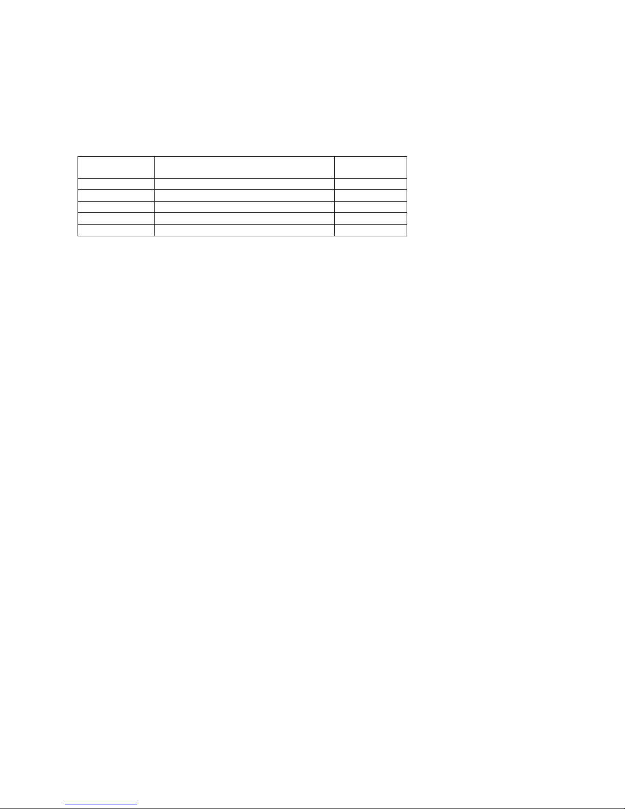
Between the water heater and the safety valve, DO NOT install an isolation valve or any other form of narrowing,
because this might disturb the correct functioning of the safety valve.
The correct safety valve has been supplied together with the S-WG water heater.
water heater
safety valves
Part number
S-WG 80
27112 Prescor B ¾ - 10 bar - 150 kW
E04.015.090
S-WG 100
27112 Prescor B ¾ - 10 bar - 150 kW
E04.015.090
S-WG 120
27112 Prescor B ¾ - 10 bar - 150 kW
E04.015.090
S-WG 150
27112 Prescor B ¾ - 10 bar - 150 kW
E04.015.090
S-WG 180
29007 Prescor B 1 - 10 bar - 250 kW
E04.015.091
The S-WG water heater and tank should be installed by a skilled installer according to all applicable standards
and regulations for tap water installations. Use the next scheme as guideline. When multiple water heaters and
tanks are applied, every combination has to be equipped with its own safety valve.
Scheme on next page
Page 8
E09.012.246 Manual S-WG
9
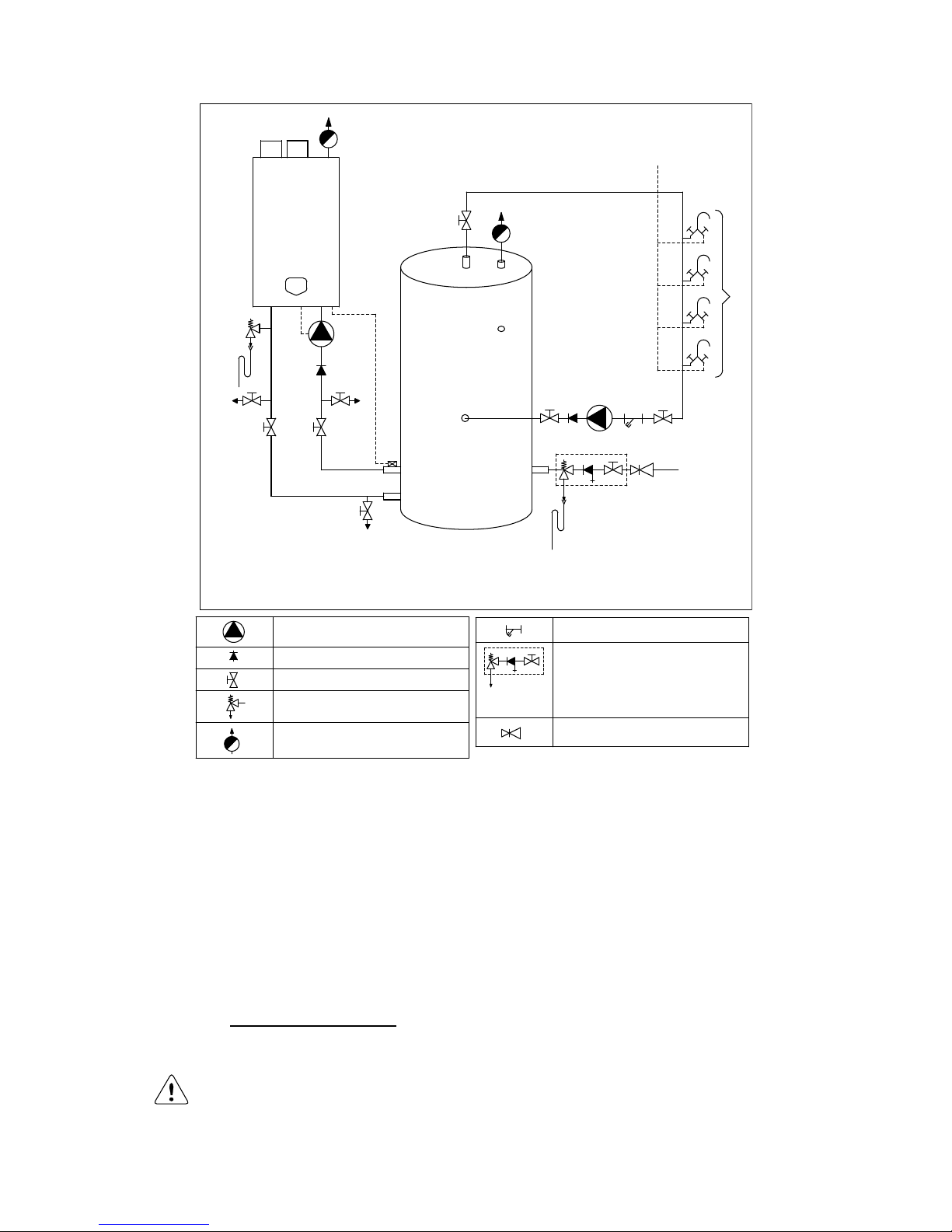
A) Cold water inlet
B) Hot water circulation flow
C) Circulation flow return
1) Pressure relief valve (mandatory in case service water pressure is too high)
2) Inlet combination with valve (mandatory)
3) Apply filter if necessary (recommended)
4) A suitable safety valve must be mounted near the water heater (mandatory)
This safety valve may never be isolated from the water heater by means of a ball valve
5) Mount remote pipe sensor as close as possible to the tank
6) Drain valve (recommended)
7) Hot and cold water mixers
SAFETY COMPONENTS
NB! The picture shows an example of a functional installation. The safety components as
shown in the picture are NOT necessarily conform the applicable standards and regulations.
ALWAYS have the installation installed by a skilled installer. Safety must be added according to all applicable standards and regulations.
1
2
3
A
B
C
4
7
A
5
6
6
6
PUMP
NON RETURN VALVE
VALVE
SAFETY VALVE
AUTOMATIC VENT
FILTER
INLET COMBINATION
- Overflow
- Controllable return valve
- Valve
PRESSURE REGULATING VALVE
Page 9
E09.012.246 Manual S-WG
10
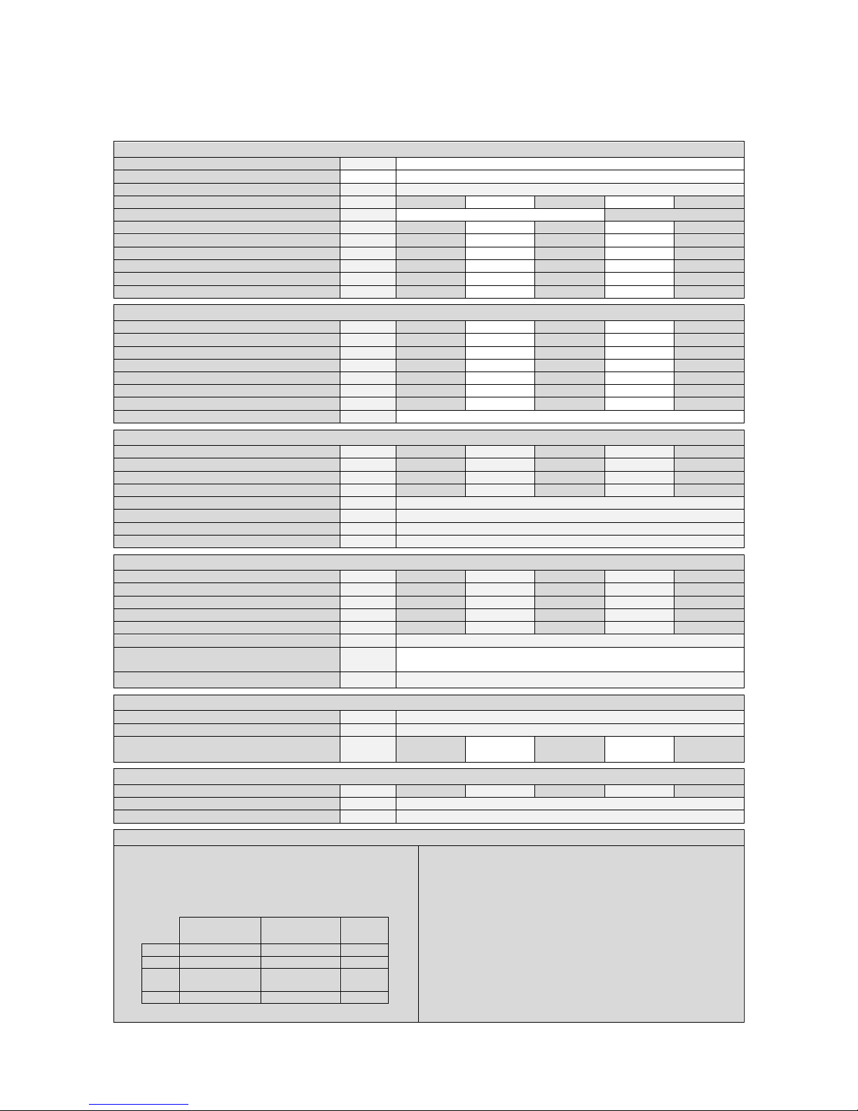
2 TECHNICAL DATA S-WG WATER HEATERS
GENERAL
Product Identification number CE 0063 BR3190
Classification
II2H3P
Gas Appliance Type
B23; B23P; C13X, C23X, C33X, C43X, C53X, C63X, C83X
Type water heater
S-WG80
S-WG100
S-WG120
S-WG150
S-WG180
Dimensions (h x w x d)
mm
842 x 476 x 486
898 x 476 x 677
Water content est.
Litre
5.0
6.5
8.3
10.4
12.9
Weight dry
kg
68
73
78
87
96
In- and outlet water connection union
inch
1½ 2 2 2 2
Gas connection
inch
R ¾
R ¾
R ¾
R 1
R 1
Flue duct flue/air inlet
mm
80/125
100/150
100/150
100/150
100/150
Parallel connection
mm
80-80
100-100
100-100
130-130
130-130
DOMESTIC HOT WATER
Nominal input min./max. (Net)
kW
14.6 - 74.3
17.2 - 92.2
26.0 - 111
34.0 - 138
45.0 - 166
Nominal input min./max. (gross) (G20 G25)
kW
16.2 - 82.5
19.1 - 102
28.9 - 123
37.8 - 153
50.0 - 184
Nominal input min./max. (gross) (G31)
kW
15.9 - 80.8
18.7 - 100
28.3 - 121
37.0 - 150
48.9 - 180
Nominal input min./max. (gross) (G30)
kW
15.8 - 80.2
18.6 – 99.7
34.7 - 120
36.8 - 150
48.8 - 180
Nom. output 80/60 at 100%
kW
14.0 - 71.2
16.5 - 88.4
24.7 - 106
32.6 - 132
43.3 - 180
Nom. output 50/30 at 100%
kW
15.2 - 77.5
18.0 - 96.2
27.2 - 116
35.5 - 144
47.3 - 160
Nom. output 37/30 at 30%
kW
15.7 - 80.1
18.6 - 99.5
28.1 - 120
36.7 - 149
48.5 - 175
Efficiency 40/30ºC DIN 4702-8
%
up to 110.6 % within the S-WG range
GAS CONSUMPTION [EN437]
Natural gas G25 min - max
m³st/h
1.80 - 9.14
2.12 - 11.35
3.20 - 13.66
4.18 - 16.98
5.54 - 20.43
Natural gas G20 min - max
m³st/h
1.54 - 7.86
1.82 - 9.76
2.75 - 11.75
3.60 - 14.60
4.76 - 17.57
Propane gas G31 min - max
m³st/h
0.60 - 3.04
0.70 - 3.77
1.06 - 4.54
1.39 - 5.65
1.84 - 6.79
Butane gas G30 min - max 1 (B/P)
m³st/h
0.45 - 2.29
0.53 - 2.85
0.99 - 3.44
1.05 - 4.28
1.40 - 5.15
Gas supply pressure nom. G25 2
mbar
25
Gas supply pressure nom. G20 2
mbar
20
Gas supply pressure nom. G31 2
mbar
30/37
Gas supply pressure nom. G30 2
mbar
50
EMISSION
CO2 flue gas G25/G20 min - max 3
%
8.7 - 9.0
8.7 - 9.0
8.7 - 9.0
8.7 - 9.0
8.7 - 9.0
CO2 flue gas G31 min - max 3
%
9.3 - 10.3
9.3 - 10.3
9.3 - 10.3
9.3 - 10.4
9.3 - 10.5
CO2 flue gas G30 min - max 3
%
9.3 - 10.4
9.3 - 10.4
9.3 - 10.4
9.3 - 10.5
9.3 - 10.6
NOx emission at 0% O
2
max.80/60 4
ppm
32.2
32.2
37.8
32.2
34.3
NOx emission at 0% O
2
max.80/60 4
mg/kWh
57.9
57.9
67.9
57.9
61.9
NOx - class [EN483 / EN15420]
-
5
Temperature flue gas estimated
@ combustion air temp 20ºC
°C
85-95
Available pressure for the flue system 5
Pa
200
INSTALLATION
Max. water temperature
°C
75
Pressure WW-system min./max.
bar
1.0-6.0
Hydraulic resistance of the water heater at
T = 17 K between in- and outlet
Head
mWC
5.8
4.7
4.1
6.0
5.5
ELECTRIC
Power consumption
W
170
170
190
250
250
Power supply
V / Hz
230 / 50
Protection class
IPX4D
NOTES
1
Using propane G31 or butane G30, maximum fan
speed needs to be reduced (parameter P4BD).
2
Below a table is given in which the min. and max.
gas supply pressures are mentioned acc. to EN437.
p nominal
[mbar]
p min
[mbar]
p max
[mbar]
G25
25
20
30
G20
20
17
25
G31
30
25
35
37
25
45
G30
50
43
57
3
CO2 of the unit measured/set without the water heater
door in place.
4
Emissions measured during unit certification.
5
Maximum combined resistance of flue gas and air supply
piping at high fire.
Page 10

E09.012.246 Manual S-WG
11
The S-WG water heater is standard set for Natural gas G20
Gases used must meet the European standard EN 437.
Water heater control includes the next programmable features:
Cascade control for up to twelve water heaters
Remote operation and heat demand indication from each water heater
Anti-Legionnaires’ disease function
0-10 VDC remote flow temperature (set point) control
0-10 VDC connection available
The water temperature can be controlled by an external 0-10 VDC signal. When a number of water heaters are
cascaded, the signal should be directed to the master only. Less than 1 Volt will switch off the water heater(s).
Time program
Time programs with three programmable periods per day are available. These time programs are activated at
the control panel and offer great flexibility in controlling the water heater’s day and night temperatures as well as
the anti-Legionella settings.
Page 11
E09.012.246 Manual S-WG
12
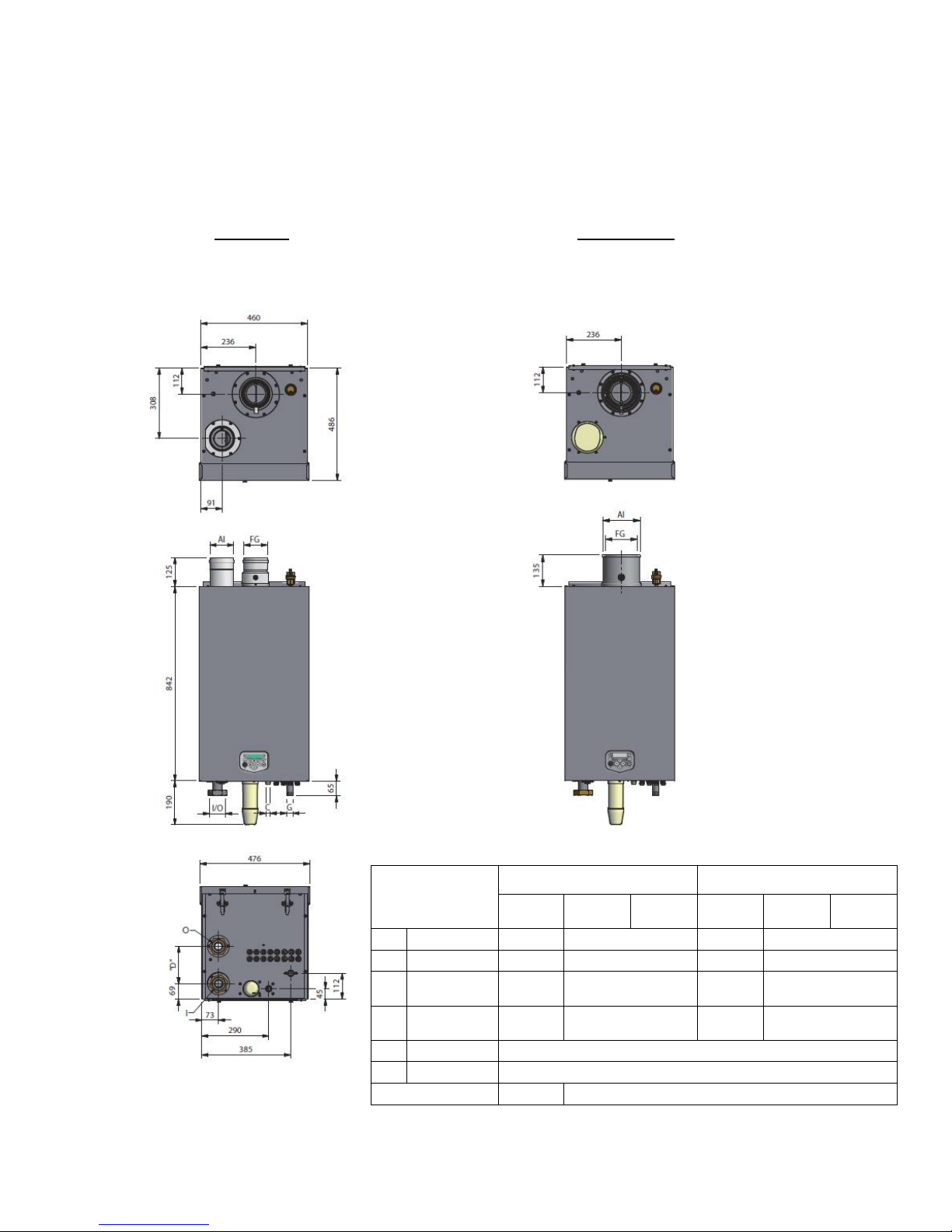
3 DIMENSIONS
3.1 Water heaters S-WG80 – S-WG120
TWIN PIPE CONCENTRIC
Connections
(mm/ ” )
twin pipe
concentric
S-
WG80
S-
WG100
S-
WG120
S-
WG80
S-
WG100
S-
WG120
FG
flue gas
Ø80
Ø100
Ø80
Ø100
AI
air inlet
Ø80
Ø100
Ø125
Ø150
I
cold water
inlet
R 1½”
(swivel)
R 2”
(swivel)
R 1½”
(swivel)
R 2” (swivel)
O
hot water
outlet
R 1½”
(swivel)
R 2”
(swivel)
R 1½”
(swivel)
R 2” (swivel)
G
gas
R ¾” (male)
C
condensate
flexible hose Ø25/21 x 750 mm.
dimension "D"
175
160
Page 12
E09.012.246 Manual S-WG
13
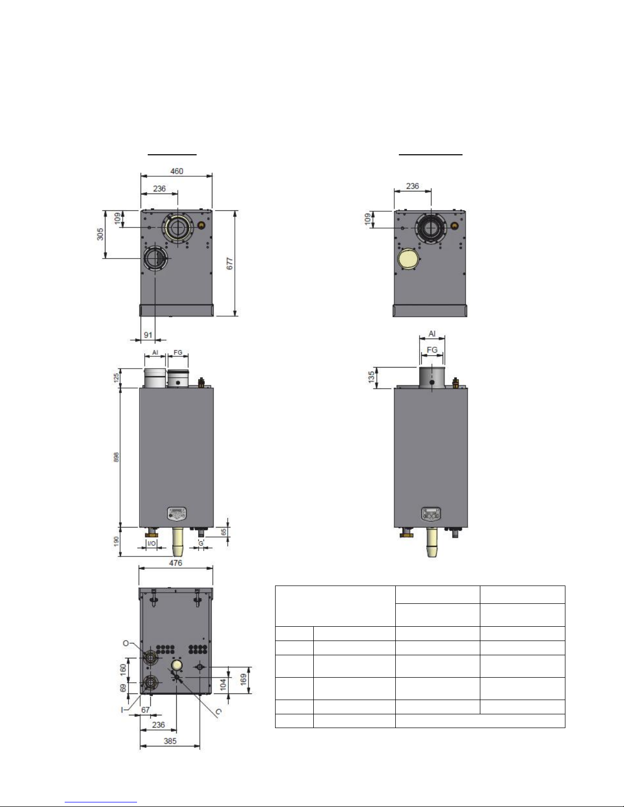
3.2 Water heaters S-WG150 and S-WG180
TWIN PIPE CONCENTRIC
Connections
(mm/ ” )
twin pipe
concentric
S-WG 150 -180
S-WG 150 -180
FG
flue gas
Ø130
Ø100
AI
air inlet
Ø130
Ø150
I
cold water inlet
Rp 2”
(swivel)
Rp 2”
(swivel)
O
hot water outlet
Rp 2”
(swivel)
Rp 2”
(swivel)
G
gas (male)
R 1”
R 1”
C
condensate
flexible hose Ø25/21 x 750 mm.
Page 13
E09.012.246 Manual S-WG
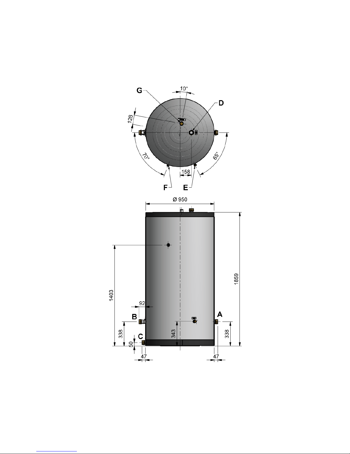
14
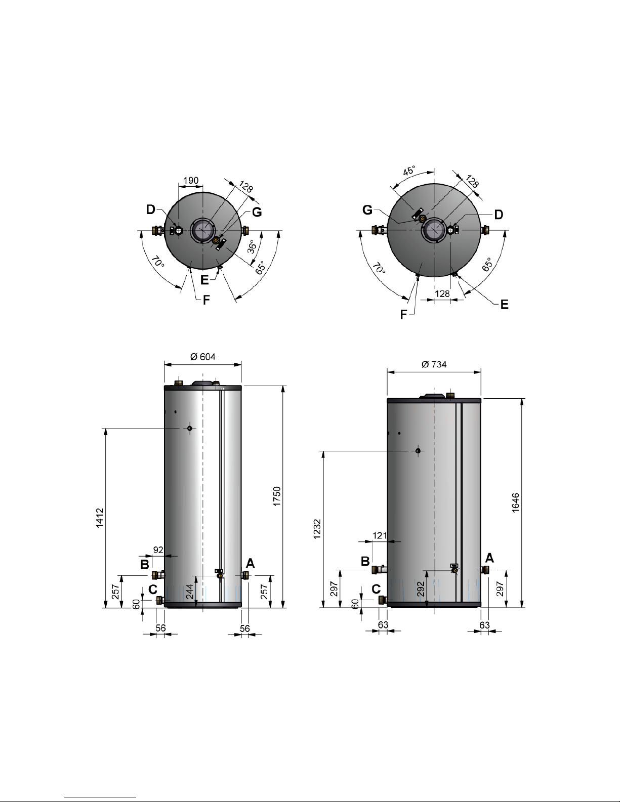
3.3 S-WG tanks
300 Ltr. 450 Ltr.
Page 14
E09.012.246 Manual S-WG
15
750 Ltr.
Page 15
E09.012.246 Manual S-WG
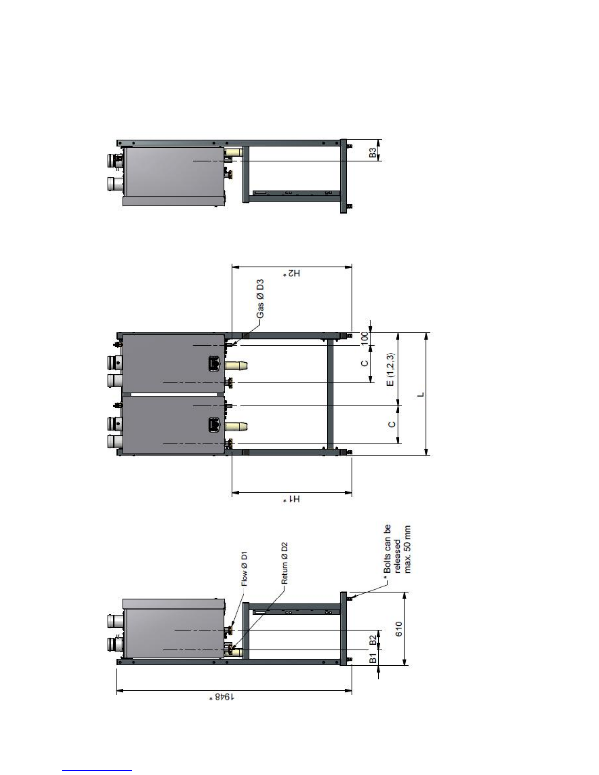
16
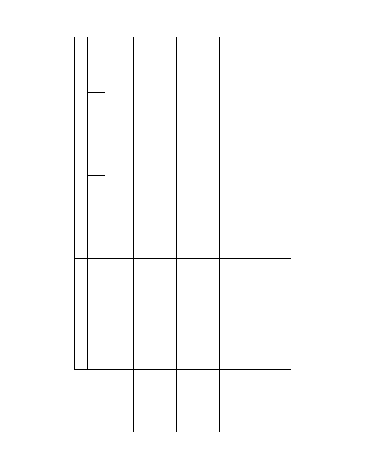
3.4 Cascade frames S-WG80 – S-WG180
Frames for two, three and four water heaters S-WG80 up to S-WG180
Page 16
E09.012.246 Manual S-WG
17
water heaters S-WG 150 - 180
4
1980
133
160
235
317
Rp 2
Rp 2
R 1"
590
1080
1570
935
935
3
1520
133
160
235
317
Rp 2
Rp 2
R 1"
605
1110
n.v.t.
935
935
2
1015
133
160
235
317
Rp 2
Rp 2
R 1"
605
n.v.t.
n.v.t.
935
935 1 510
133
160
235
317
Rp 2
Rp 2
R 1"
n.v.t.
n.v.t.
n.v.t.
935
935
water heaters S-WG 100 - 120
4
1980
133
160
177
314
Rp 2
Rp 2
R ¾"
590
1080
1570
990
990
3
1520
133
160
177
314
Rp 2
Rp 2
R ¾"
605
1110
n.v.t.
990
990
2
1015
133
160
177
314
Rp 2
Rp 2
R ¾"
605
n.v.t.
n.v.t.
990
990
1
510
133
160
177
314
Rp 2
Rp 2
R ¾"
n.v.t.
n.v.t.
n.v.t.
990
990
water heaters S-WG 80
4
1980
133
175
177
310
Rp 1½
Rp 1½
R ¾"
590
1080
1570
990
990
3
1520
133
175
177
310
Rp 1½
Rp 1½
R ¾"
605
1110
n.v.t.
990
990
2
1015
133
175
177
310
Rp 1½
Rp 1½
R ¾"
605
n.v.t.
n.v.t.
990
990 1 510
133
175
177
310
Rp 1½
Rp 1½
R ¾"
n.v.t.
n.v.t.
n.v.t.
990
990
Number of water
heaters cascaded
L (frame)
B1 (return)
B2 (return/flow)
B3 (gas)
C (water/gas)
D1 (flow)
D2 (return)
D3 (gas)
E1 (gas 2nd water
heater)
E2 (gas 3rd water
heater)
E3 (gas 4th water
heater)
H1 (flow/return)
H2 (gas)
Page 17

E09.012.246 Manual S-WG
18
4 ACCESSORIES AND UNPACKING
4.1 Accessories
Depending on the selected way of controlling the system, the following items can be supplied with the water
heater. Ask your supplier for the specifications.
Item
Part no.
1
External DHW-Tank temperature sensor 10kOhm@25°C, to be mounted on the tank
outlet to the water heater
E04.016.304
2
S-WG 80 water heater: Conversion set for concentric to parallel flue and air terminal
(80/125→80-80)
E61.001.163
3
S-WG 80 water heater: Conversion set for parallel to concentric flue-air terminal
(80-80→80/125)
E61.001.170
4
S-WG 100 - 120 water heater: Conversion set for concentric to parallel flue and air
terminal
(100/150→100-100)
E61.001.164
5
S-WG 100 - 120 water heater: Conversion set for parallel to concentric flue-air terminal (100-100→100/150)
E61.001.171
6
S-WG 150 - 180 water heater: Conversion set for concentric to parallel flue and air
terminal (100/150→130-130)
E61.001.179
7
S-WG 150 - 180 water heater: Conversion set for parallel to concentric flue-air terminal (130-130→100/150)
E61.001.180
8
Remote control DHW temperature ‘Open Therm’ RCW (modulating)
E04.016.645
9
Software set for diagnose, programming and temperature read out
E09.000.105
10
Hot water tank, stainless steel, 300 litres
E66.000.203
11
Hot water tank, stainless steel, 450 litres
E66.000.204
12
Hot water tank, stainless steel, 750 litres
E66.000.205
13
Interface cable between water heater control and computer (laptop) with USB connection
E04.016.586
4.2 Unpacking
The S-WG water heater will be supplied with the following documents and accessories:
One “Installation, Operating and Maintenance Manual”
One suspension bracket with locking plate and bolts
Attached to a connection tube:
~ One safety relief valve, to be mounted conform the applicable standards and regulations
Attached to the front of the gas valve:
~ Three spare nuts for mounting the burner plate
~ Two spare fuses for the water heater control
~ One sticker for propane or butane operation
Bottom part of the siphon, temperature sensor and connector
Two nipples with gaskets for inlet/outlet connections of the water heater
NB! A pump is separately supplied, it’s not included in the water heater supply. For pump choice, see § 9.5.
After delivery, immediately check the water heater package to see if it is complete and without any defects. Re-
port any imperfections immediately to your supplier.
Page 18
E09.012.246 Manual S-WG
19
5 INSTALLATION OF THE S-WG
5.1 General notes
At every side of the water heater at least 50 mm of clearance should be applied to walls or wall units, 350 mm
above the top side of the water heater and 250 mm from the bottom of the water heater.
The installation area/room must have the following provisions:
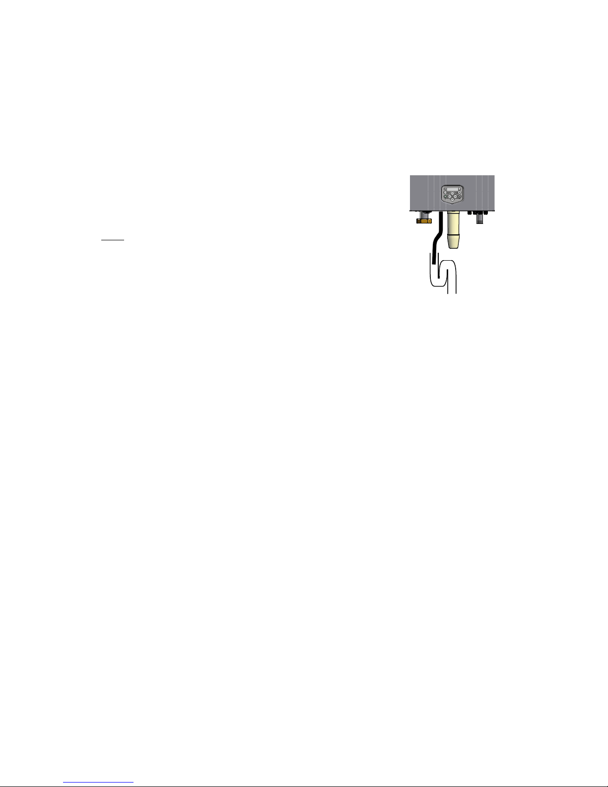
230 V - 50 Hz power source socket with earth connection.
Open connection to the sewer system for draining condensing water:
Note:
The wall used for mounting the water heater must be able to hold the weight of the water heater. If this is not the
case it is recommended to mount the water heater on a (cascade) frame.
Other considerations related to the water heater location:
The ventilation of the plant room must meet all applicable standards and regulations, regardless of the
selected supply of fresh air to the water heater location.
Both the air supply and the flue gas tubes must be connected to the outside wall and/or the outside roof.
The installation area must be dry and frost-free.
The water heater has a built-in fan that will generate noise, depending on the total heat demand. The wa-
ter heater location should minimise any disturbance this might cause. Preferably it is suggested to mount
the water heater on a brick wall.
There must be sufficient lighting available in the plant room to work safely on the water heater.
Remind the positioning of electrical components in relation to the temperature sensitivity.
Make sure there is an open connection with the sewer to drain the condensate. This connection should
be lower than the condensate drain level of the water heater.
The water heater must be positioned and installed by a certified installer in accordance with all applicable standards and regulations. Commissioning of the water heater must be done by a skilled service/commissioning
engineer.
Page 19
E09.012.246 Manual S-WG
20
5.2 Mounting the water heater and tank
5.2.1 WATER HEATER MOUNTING
Before mounting and installing the water heater the following connections should be considered:
Flue gas system and the flue gas pipe connections
Air supply system and connections
‘Cold in’ and ‘hot out’ pipe connection
Condensate and pressure relief valve drainage
Power supply (preferably the power connection is positioned above the water heater)
All lines/piping must be mounted free of tension. The weight of all the installation components should be
supported separately from the water heater so there will be no standing force on the connections.
This might influence the mounting position of the water heater.
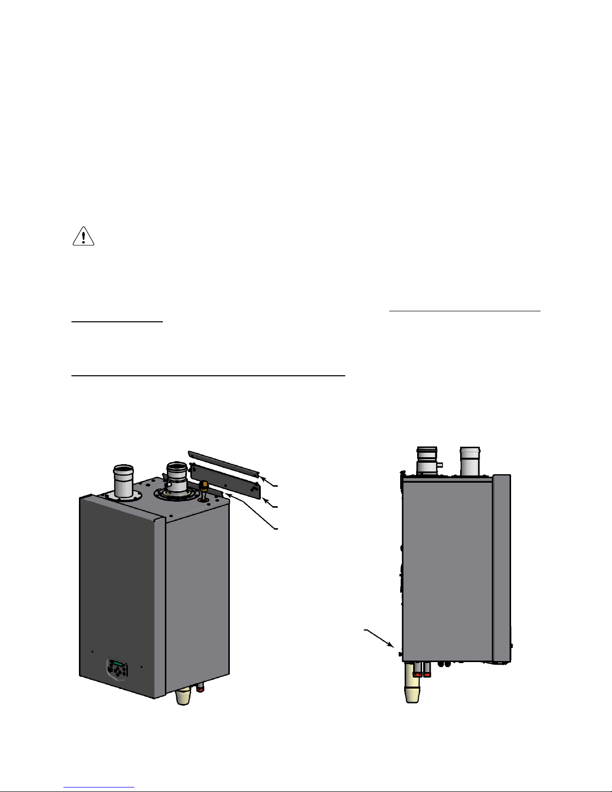
Determine the position of the flow and return pipes by using the included suspension bracket or a suspension
frame (when supplied).
While marking the holes, ensure that the suspension bracket or frame is perpendicular and the water heater
does not lean forward. If necessary adjust the position with the adjusting bolts at the lower rear side of the back
panel (see drawing). When the adjusting bolts aren’t sufficient, fill the gap behind the bolts to get the water
heater in position. The exact water heater position lies between the water heater hanging level and hanging
slightly backwards.
The water heater should not lean forward in the mounted position.
Lock the suspension bracket with the security cover before making any other connections to the water heater.
This security cover will prevent the water heater from falling off the bracket. Don't use excessive force during the
mounting of the water heater connections.
3. Lock water heater with
locking plate and two bolts
1. Attach mounting bracket to wall
with inclined side facing upwards
2. Suspend water heater with suspen-
sion bracket on mounting bracket
4. Level water heater using
adjusting bolts
Page 20
E09.012.246 Manual S-WG
21
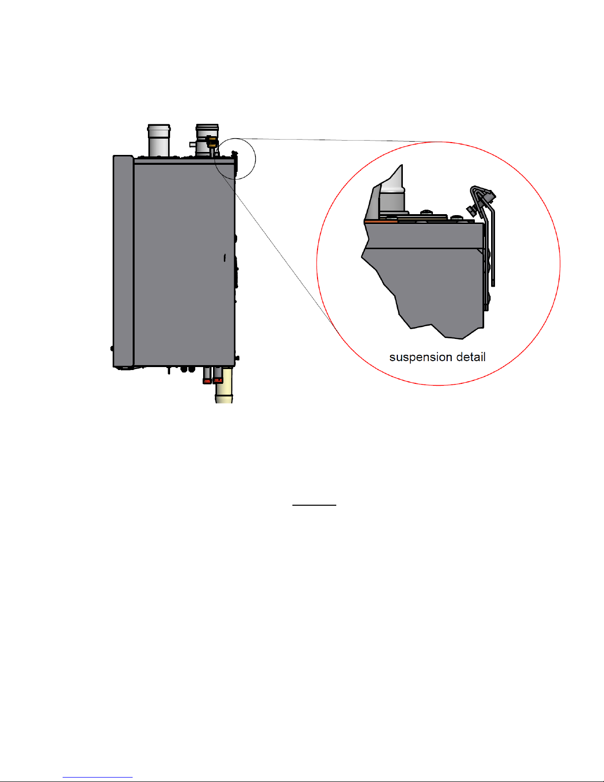
Detailed drawing of the water heater mounting and the fixation of the locking plate.
5.2.2 TANK POSITIONING
The tank can be placed at will* on a stable floor, but not too far from the water heater(s). See § 9.4.3, ‘Interconnecting pipes – equivalent length’, on page 50.
* NB! This floor must be able to hold the weight of the water filled tank(s).
Page 21

E09.012.246 Manual S-WG
22
6 FLUE GAS AND AIR SUPPLY SYSTEM
6.1 General
The water heater has a positive pressure flue system. The available combined pressure drop for the inlet and
outlet system, for a single water heater, is 200 Pa for the complete water heater range. For a multiple water
heater installation, always contact the manufacturer for advice.
Notice:
Install the horizontal flue components with an angle of 3° downwards in the direction of the water heater
(roughly equal to five centimetres for every linear meter). When not installed accordingly, it may result in
condensate building-up in the flue gas tube, eventually causing component failure.
Wall flue terminals are generally used up to 80 kW. Using these terminals with larger capacities will give
unpleasant large condensate clouds.
When using a wall terminal, there is the possible risk of ice building-up on surrounding parts/structures,
because the condensate will freeze. This risk should be taken into account during the design phase of the
DHW installation.
Note:
Because the flue gases can have a relatively low temperature, the water heater needs to have a high efficiency
approved stainless steel or plastic flue system. These materials should be usable for the applied pressure in the
flue gas system, be condensate proof and have a temperature class of T-120.
6.2 Air supply
When an air supply duct is connected from the outside of the building to the water heater, the water heater will
operate as a room-independent water heater (closed water heater).
The air supply duct can be made of:
PVC / PPs
Thin-walled aluminium
Stainless steel
NOTICE: When the supply duct will be placed in a plant room with moist air (for example: greenhouses), a sufficiently insulated duct must be used to prevent the possible condensation at the outside of the duct. It is not possible to insulate the internal air pipes of the water heater and therefore condensation at the internal air canals
must be prevented. The air supply duct needs to be protected against rain falling on top of the roof, so no rain
water will enter the water heater.
6.3 Flue terminal
Never use aluminium (containing) flue gas materials for this water heater
The flue terminal duct can be made of:
Stainless steel with T-120 gaskets
PPs temperature class T-120
Page 22
E09.012.246 Manual S-WG
23
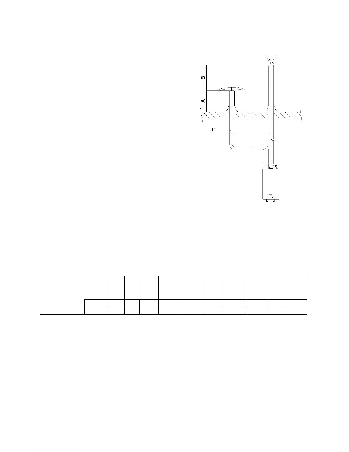
Height A
This is the height of the air inlet. A rain hood should prevent rainwater entering the air supply system.
When the inlet and outlet are mounted on a flat roof, the inlet
should be at least 60 cm above the roof surface and at least
30 cm above the maximum snow level.
Example 1:
When the maximum snow level on the roof surface is 45 cm
then the air inlet should be at 45+30=75 cm. 75 cm is more
than the minimum 60 so the height will be 75 cm.
Example 2:
When the maximum snow level on the roof surface is 15 cm
then the air inlet should be at 15+30=45 cm. 45 cm is less
than the minimum 60 cm so the height will be 60 cm.
Height B
This is the height of the flue outlet related to the air inlet.
The flue gas outlet should be at least 70 cm above the air inlet. It is advised to be equipped with a conical outlet.
A single flue outlet should be situated at least 100 cm
above the roof surface.
Distance C
The horizontal distance between the flue gas pipe and air
inlet pipe at roof level.
This distance should be at least 70 cm.
6.4 Flue system classification B23P
Overpressure flue gas systems
For classification B23P and for overpressure flue gas systems the minimum requirements of the flue gas material for S-WG appliances can be determined in a designation string according to the EN1443 (see table).
CE string flue gas
material (B23P)
European
standard
Temperature
class
Pressure
class
Resistance to
condensate
Corrosion
resistance
class
Metal:
liner
specifications
Soot fire
resistance
class
Distance
to combustible material
Plastics:
location
Plastics:
fire behaviour
Plastics:
enclosure
min. requirement PPs
EN 14471
T120
P1 W 1 O
30
I or E
C/E
L
min. requirement StS
EN 1856-1
T120
P1 W 1
L20040 O 40
A few examples of flue gas material suitable for S-WG water heaters:
CE String for Plastic PPs: EN14471 T120 P1 W 2 O(30) I C/E L
CE String for Stainless Steel: EN1856-1 T250 P1 W V2-L50040 )(50)
When selecting flue gas systems, be aware that the minimum requirements are met. So only select flue gas
materials having the same or better properties than this table.
6.5 Flue system classification C63
In general, appliances are certified with their own flue gas material. If a water heater is C63 certified, no specific
type flue gas material has been certified in combination with the water heater. In this case the flue gas material
does not need to be certified in combination with the water heater but should be fit for purpose, and comply with
the applicable European standards. It must be able to handle the condensate forming and transport, overpressure and must have a minimum temperature class of T120.
Page 23

E09.012.246 Manual S-WG
24
6.6 Combustion air quality
Combustion air must be free of contaminants. For example: chlorine, ammonia and/or alkali agents, dust, sand
and pollen. Remind that installing a water heater near a swimming pool, a washing machine, laundry or chemical
plants does expose combustion air to these contaminants.
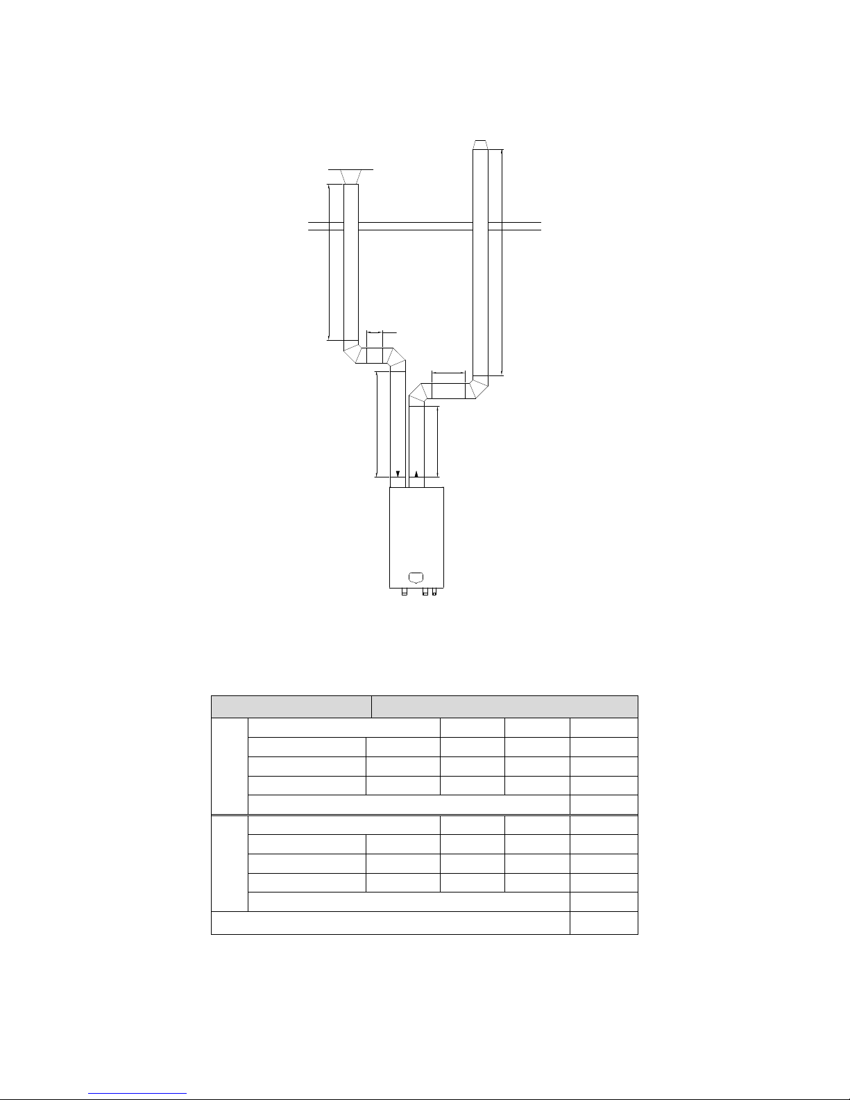
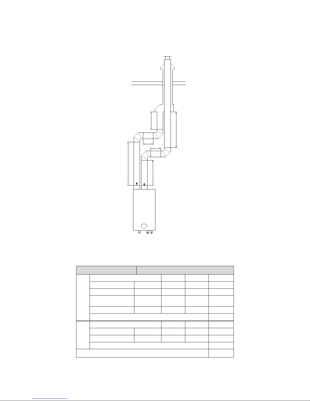
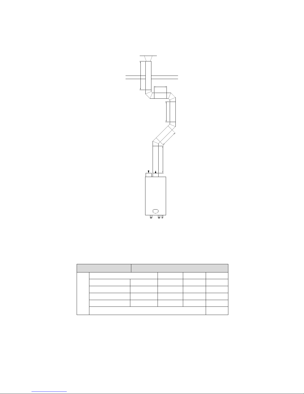
6.7 Flue gas & air inlet calculation examples (next pages)
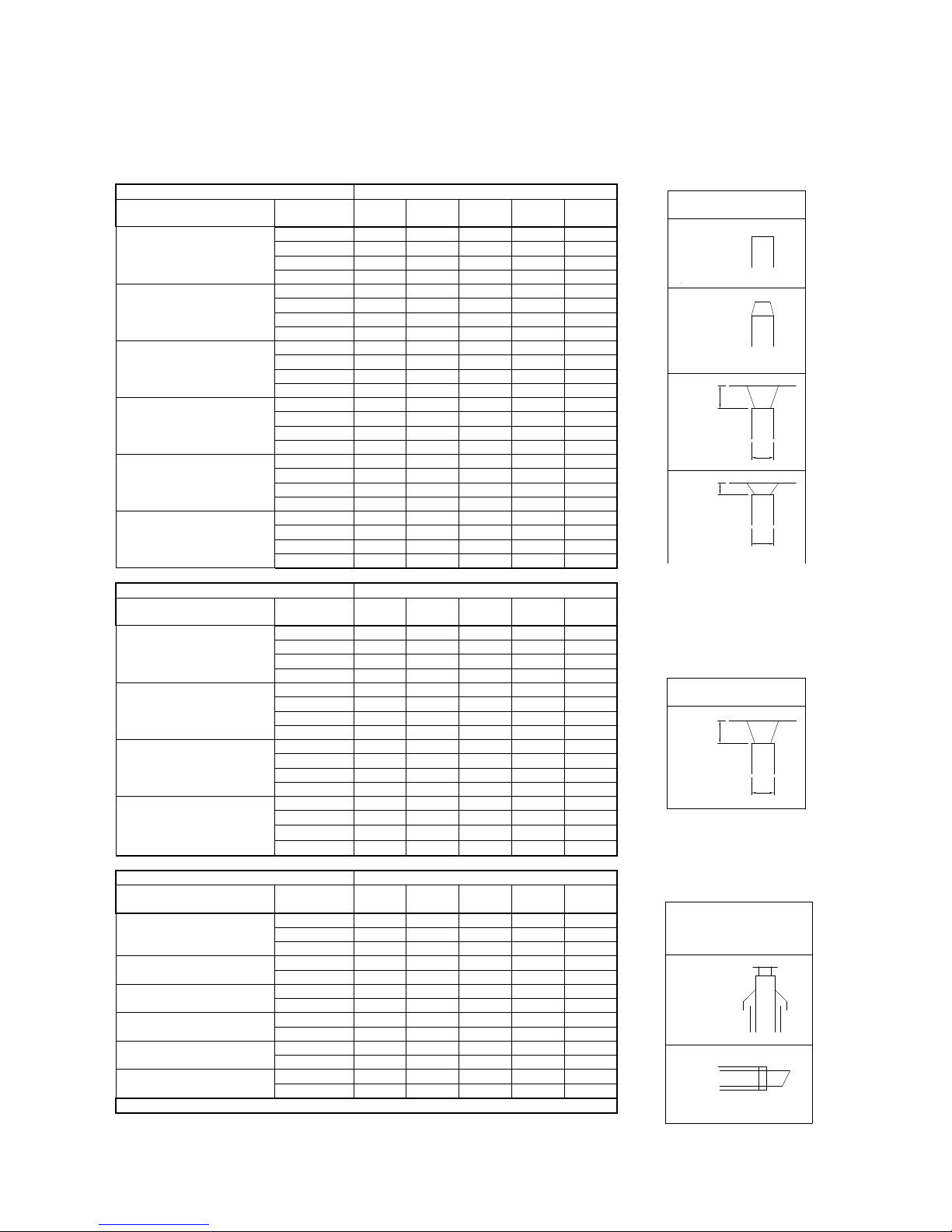
For several flue gas & air inlet combinations the maximum length of the pipes will be calculated using the given
table:
A: Twin pipe system with separate pipes for flue gas and air supply
B: Twin pipe system with separate pipes and concentric roof terminal
C: Single pipe for flue gas outlet only (air supply from plant room)
Page 24
E09.012.246 Manual S-WG
25
Flue gas and air supply resistance table
NOTICE: This table can only be used for a single flue/air system for one water heater. Do NOT use this table for
common flue/air systems with cascaded water heaters.
FLUE GAS PIPING
RESISTANCE [Pa]
Ø [mm] *
S-
WG80
S-
WG100
S-
WG120
S-
WG150
S-
WG180
straight tube/m
80
8.0 - - - -
100
3.5
4.0
6.5 - -
130
0.8
1.2
1.8
3.8
6.0
150
-
0.5
0.8
1.7
3.0
45° bend
80
4.0 - - - -
100
1.7
2.0
3.2 - -
130
0.4
0.6
0.8
1.9
3.0
150
-
0.2
0.4
0.8
1.5
90° bend
80
8.0 - - - -
100
3.5
4.0
6.5 - -
130
0.8
1.2
1.8
3.8
6.0
150
-
0.5
0.7
1.7
3
Flue outlet zeta=0.05
80
1.2 - - - -
100
0.5
0.8
1.1 - -
130
0.18
0.3
0.4
0.6
0.9
150
-
0.15
0.2
0.35
0.5
Flue outlet zeta=1.0
80
24 - - - -
100
9.8
15.2
22.1 - -
130
3.5
5.3
7.8
12
17.3
150
-
3.0
4.4
6.8
9.8
Flue outlet zeta=1.5
80
36 - - - -
100
14.8
22.8
33.2 - -
130
5.2
8.0
11.6
18
26
150
-
4.5
6.6
10.2
14.7
AIR SUPPLY PIPING
RESISTANCE [Pa]
Ø [mm] *
S-
WG80
S-
WG100
S-
WG120
S-
WG150
S-
WG180
straight tube/m
80
7.5 - - - -
100
3.0
3.5
4.0 - -
130
0.75
0.8
1.1
1.2
2.0
150
-
0.3
0.4
0.6
1.2
45° bend
80
3.5 - - - -
100
1.5
1.7 2 -
-
130
0.4
0.4
0.5
0.6
1.0
150
-
0.15
0.2
0.3
0.6
90° bend
80
7.0 - - - -
100
3.0
3.5
4.0 - -
130
0.7
0.8
1.1
1.2
2.0
150
-
0.3
0.4
0.6
1.2
Air inlet zeta=1.0
80
18.1 - - - -
100
7.4
11.4
16.7 - -
130
2.6
4.0
5.8
9.1
13.1
150
-
2.3
3.3
5.1
7.4
CONCENTRIC PARTS
RESISTANCE [Pa]
Ø [mm] *
S-
WG80
S-
WG100
S-
WG120
S-
WG150
S-
WG180
roof terminal
80/125
61 - - - -
100/150
-
39
45
69
86
130/200
- - -
15
23
outside wall terminal
80/125
22 - - - -
100/150
-
19
24
40
48
straight tube/m
80/125
12 - - - -
100/150
-
8.0
10
14
16
45° bend conc.
80/125
7 - - - -
100/150
-
8.0
9.0
14
16
90° bend conc.
80/125
13 - - - -
100/150
-
11
13
22
28
conc./par. adaptor
80/125
14 - - - -
100/150
-
16
22
40
56
* Do not reduce pipe diameters relative to water heater connections
Roof
FLUE GAS OUTLET
AIR INLET
CONCENTRIC
Wall
H
D
H/D=1,0
zeta=1,0
AIR INLET
H
D
H/D=0,5
zeta=1,5
H
D
H/D=1,0
zeta=1,0
conical outlet
zeta=0,05
FLUE GAS OUTLET
open outlet
zeta=0
zeta = 0.0
open outlet
zeta = 0.05
conical outlet
H/D = 1.0
zeta = 1.0
H/D = 0.5
zeta = 1.5
H/D = 1.0
zeta = 1.0
Roof
Wall
FLUE GAS OUTLET
AIR INLET
CONCENTRIC
FLUE GAS OUTLET
AIR INLET
Page 25
E09.012.246 Manual S-WG
26
A: Twin pipe system with separate pipes for flue gas and air supply.
Example A
The total resistance is less than 200 Pa. This flue gas/air supply system is functional.
180
4m
2m
2m
2m
2m
5m
Water heater type:
S-WG 180
Flue gas
Diameter: 130 mm.
Number
Pa
Pa total
Straight tube m¹
total 9 6
54
Bend
90° 2 6
12
Flue outlet
conical
1
0.9
0.9
Total resistance flue gas outlet:
66.9
Air supply
Diameter: 130 mm.
Number
Pa
Pa total
Straight tube m¹
total 8 2
16
Bend
90° 2 2
4
Air inlet
H/D = 1.0
1
13.1
13.1
Total resistance air supply:
33.1
Total resistance flue gas outlet and air supply:
100 Pa
Page 26
E09.012.246 Manual S-WG
27
B: Twin pipe system with separate pipes and concentric roof terminal.
Example B
The total resistance is less than 200 Pa. This flue gas/air supply system is functional.
120
2m
2m
2m
2m
2m
2m
Water heater type:
S-WG 120
Flue gas
Diameter: 100 mm.
Number
Pa
Pa total
Straight tube m¹
total
6
6.5
39
Bend
90° 2 6.5
13
Roof terminal
concentric
150/100
1
45
45
Adaptor conc./par.
150/100
1
22
22
Total resistance flue gas outlet:
119
Air sup-
ply
Diameter: 100 mm.
Number
Pa
Pa total
Straight tube m¹
total 6 4
24
Bend
90° 2 4
8
Total resistance air supply:
32
Total resistance flue gas outlet and air supply:
151 Pa
Page 27
E09.012.246 Manual S-WG
28
C: Single pipe for flue gas outlet only (air supply from plant room).
Example C
The total resistance is less than 200 Pa. This flue gas/air supply system is functional.
100
4m
2m
3m
2
m
2m
Water heater type:
S-WG 100
Flue gas
Diameter: 100 mm.
Number
Pa
Pa total
Straight tube m¹
total
13 4 52
Bend
90° 2 4
8
Bend
45° 2 2
4
Flue outlet
H/D = 1.0
1
15.2
15.2
Total resistance flue gas outlet:
79.2
Page 28
E09.012.246 Manual S-WG
29
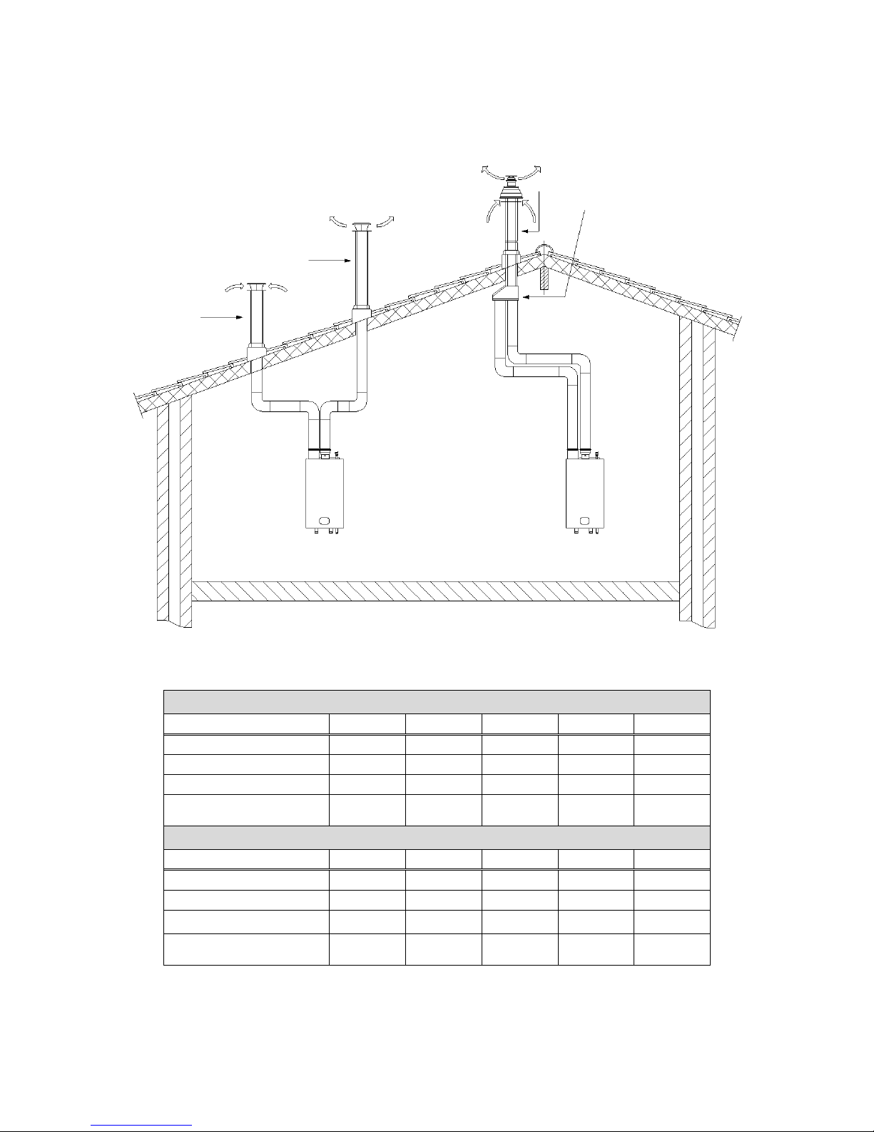
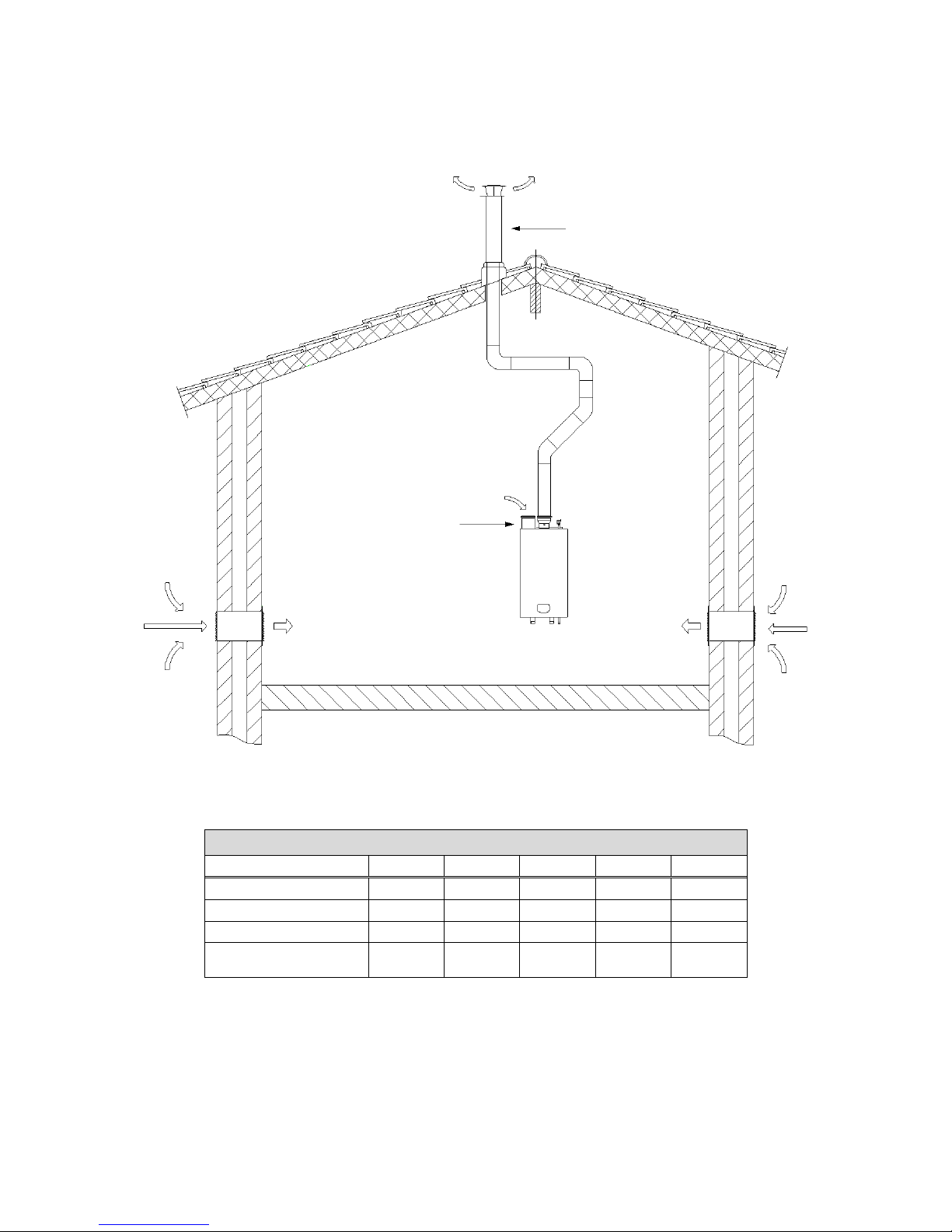
Twin pipe system: flue gas and air supply positions.
Example A
water heater type
S-WG80
S-WG100
S-WG120
S-WG150
S-WG180
Diameter air inlet
80
100
100
130
130
Diameter flue outlet
80
100
100
130
130
Diameter roof terminals
80
100
100
130
130
Maximum pipe length
(inlet + outlet together)
18.0
31.5
24.0
44.5
30.0
Example B
water heater type
S-WG80
S-WG100
S-WG120
S-WG150
S-WG180
Diameter air inlet
80
100
100
130
130
Diameter flue outlet
80
100
100
130
130
Concentric roof terminal
80/125
100/150
100/150
130/200
130/200
Maximum pipe length
(inlet + outlet together)
12.0
23.0
16.5
40.5
25.5
Concentric roof terminal
Air inlet
Flue outlet
Example A
Example B
concentric/parallel adaptor
Page 29
E09.012.246 Manual S-WG
30
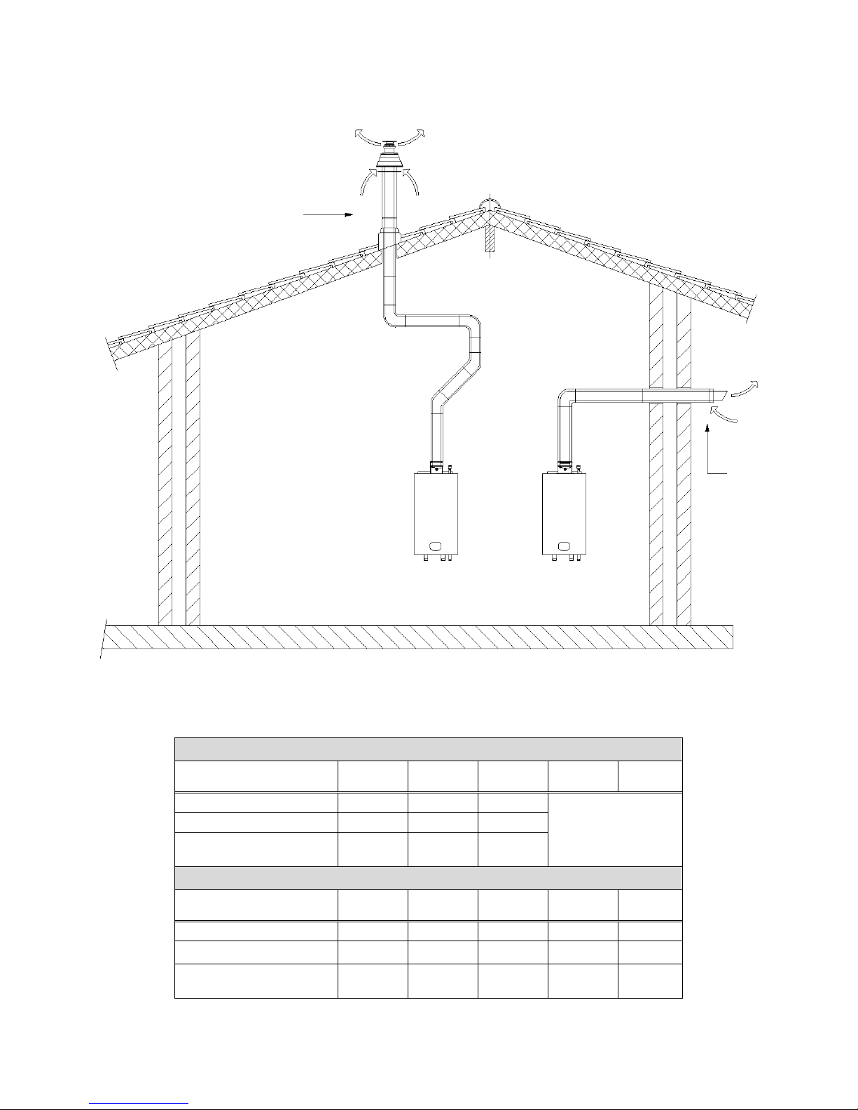
Single pipe system: flue gas positions:
Example C
water heater type
S-WG80
S-WG100
S-WG120
S-WG150
S-WG180
Diameter air inlet
80
100
100
130
130
Diameter flue outlet
80
100
100
130
130
Diam. roof terminal
80
100
100
130
130
Maximum pipe length
(total outlet length)
21.5
46.5
27.5
49.5
30.0
Example C
Vented area
Air inlet
Flue outlet
Page 30
E09.012.246 Manual S-WG
31
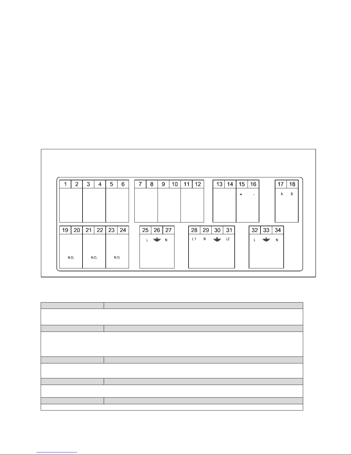
Concentric pipe system: flue gas positions:
Example D
water heater type
S-WG80
S-WG100
S-WG120
S-WG150
S-
WG180
Diameter concentric pipe
80/125
100/150
100/150
NOT
RECOMMENDED
(choose B, C or E)
Concentric roof terminal
80/125
100/150
100/150
Maximum pipe length
7.0
14.5
10.0
Example E
water heater type
S-WG80
S-WG100
S-WG120
S-WG150
S-
WG180
Diameter concentric pipe
80/125
100/150
100/150
100/150
100/150
Concentric wall terminal
80/125
100/150
100/150
100/150
100/150
Maximum pipe length
12.5
20.0
15.0
8.5
6.5
Concentric roof terminal
Concentric
wall
terminal
Example D
Example E
Page 31
E09.012.246 Manual S-WG
32
7 ELECTRICAL INSTALLATION
7.1 General
All the wiring is connected to a separate connector that is fitted in a socket. The connector can be taken from the
sockets without loosening the wiring. The connections are placed on top of the display panel and can be accessed by removing the water heater front door and the connector protection cover.
For operation the water heater needs a power supply of 230 Vac 50Hz.
The water heater connections are not life/neutral sensitive (the water heater is not phase-sensitive).
The wiring for the connections can be entered at the bottom of the water heater through the cable glands.
NOTICE: Before starting to work on the water heater, it must be switched off and the power supply to the
water heater must be disconnected.
Electrical wiring should be installed according to all applicable standards and regulations.
Working on the water heater should only be done by a skilled service engineer/installer and according to
all applicable standards and regulations.
7.2 Electrical connections
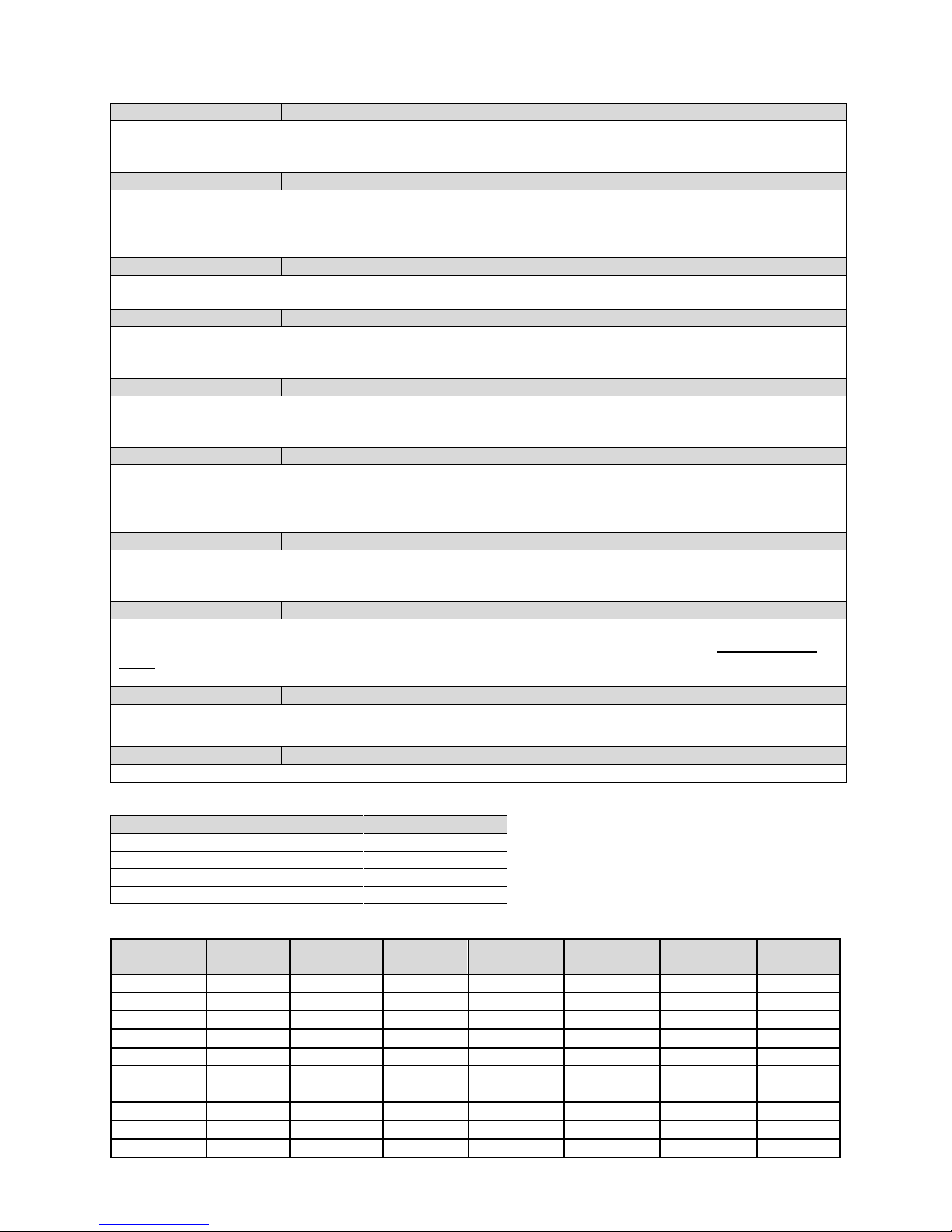
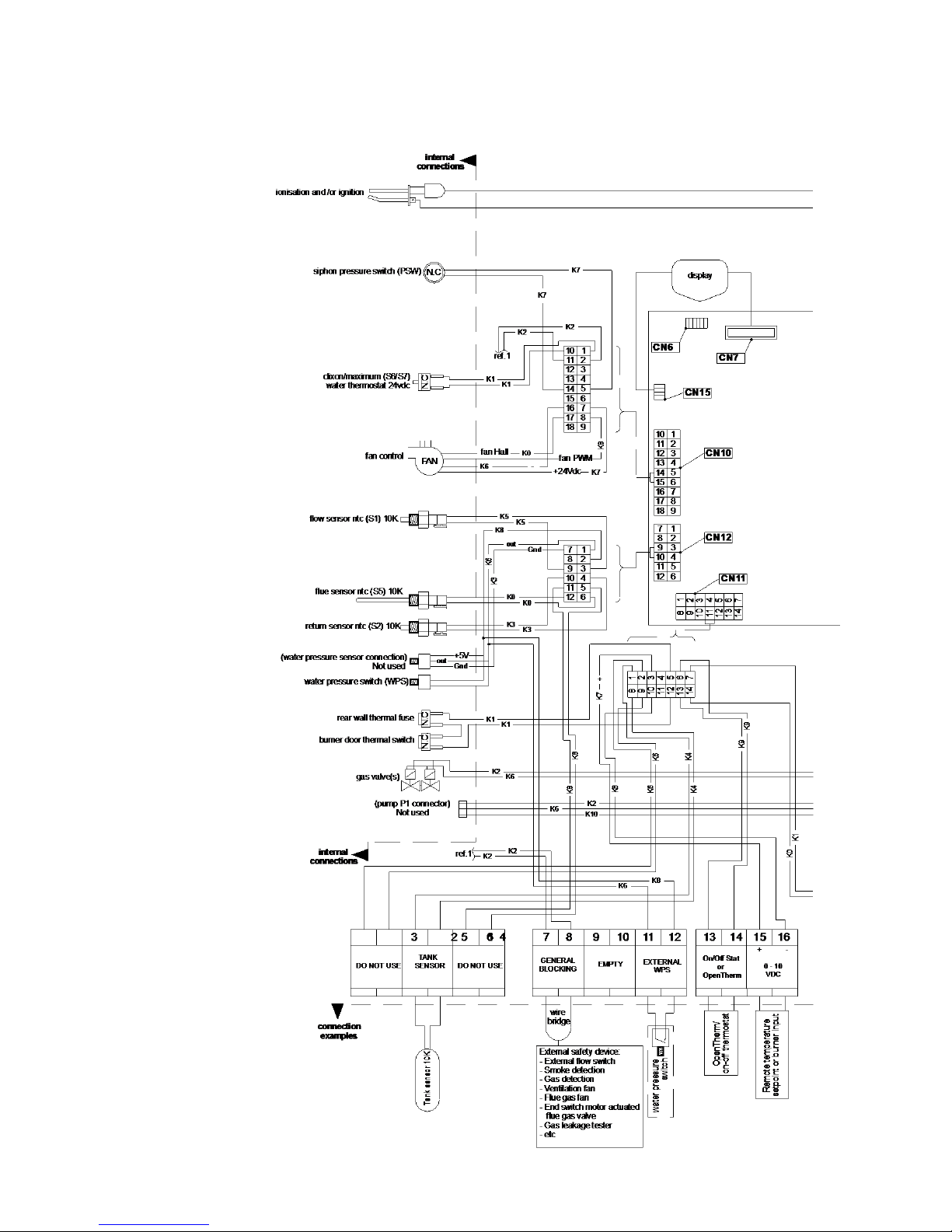
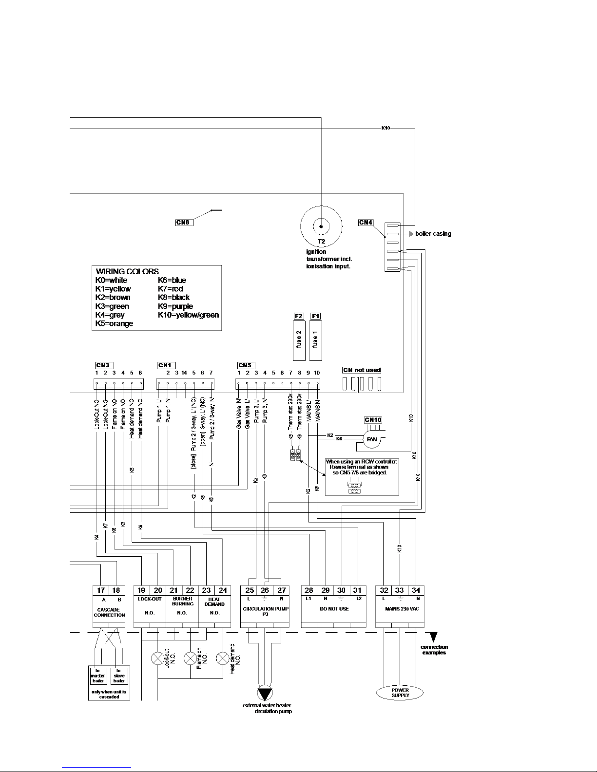
The following table describes the function of all connections of the water heater.
1-2
DO NOT USE
Do not connect any cable to these connections
3-4
TANK SENSOR
This external flow sensor measures the flow temperature at the system side. The sensor must be mounted
on the supply pipe at the system side, close to the tank. NOTICE: The sensor must be used when several
water heaters are cascaded with the internal cascade manager.
PARAMETER: No parameter settings needed.
5-6
DO NOT USE
Do not connect any cable to these connections
7-8
GENERAL BLOCKING
A heat demand that will start the burner will be blocked when terminals 7 and 8 are not bridged. This connection is for the use of external safety devices (terminals must be bridged for allowing burner to fire).
9-10
EMPTY
Table is continued
DO NOT
USE
TANK
SENSOR
DO NOT
USE
GENERAL
BLOCKING
EMPTY
EXTERNAL
WPS
ON/OFF STAT
OR
OPEN THERM
0 -10
VDC
CASCADE
CONNECTION
LOCK-OUT
BURNER
BURNING
HEAT
DEMAND
CIRCULATION
PUMP P3
DO NOT USE
MAINS 230 VAC
CONNECTIONS
Page 32
E09.012.246 Manual S-WG
33
11-12
EXTERNAL WATER PRESSURE SWITCH
A water pressure switch is mounted in the water heater. As an option an external water pressure switch can be
wired to the terminals. In this case remove connectors from ‘internal water pressure switch’. When terminals
11-12 are not bridged, the water heater will lock-out. PARAMETER: A parameter change is needed.
13-14
ON/OFF STAT OR OPENTHERM WATER TANK
OPTION 1: an ON/OFF thermostat can be connected. The water heater will use the set/programmed tank temperature when these terminals 13 and 14 are bridged.
OPTION 2: an OpenTherm (OT) controller can be connected to the terminals 13 and 14. The water heater
software will detect and use this OpenTherm signal automatically.
15-16
0-10 VDC CONTROL SIGNAL
These terminals are used for an external 0-10 VDC control signal. PARAMETER: A parameter change is
needed. NOTICE: Terminal 15 [+] (positive) and terminal 16 [-] (negative).
17-18
CASCADE CONNECTION
These connections are used when water heaters are cascaded with the internal cascade manager for controlling the total cascade. NOTICE: Connect all terminals 17 and all terminals 18 together, do not switch between
these terminals.
19-20
LOCK-OUT OR PUMP ON/OFF
This contact is N.O. (normally open). When the unit is in lock-out this contact will close.
This contact can also be used for the switching of a pump with a separate control input connection.
(PARAMETER: A parameter change is needed).
21-22
BURNER ACTIVE OR EXTRA WATER HEATER OR PUMP ON/OFF
This contact is N.O. (normally open). When the unit starts the burner and detects the flame, this contact will be
closed. This contact can also be used to control an external (extra) water heater. This contact can also be used
for the switching of a pump with a separate control input connection.
(PARAMETER: A parameter change is needed).
23-24
BURNER DEMAND OR PUMP ON/OFF
This contact is N.O. (normally open). When the unit receives any heat demand this contact will close.
This contact can also be used for the switching of a pump with a separate control input connection.
(PARAMETER: A parameter change is needed).
25-26-27
CIRCULATION PUMP P3
Each boiler should be installed with an external pump.
Make use of a relay between this pump and terminal 25-27, when the pump consumes more than 450
Watt.
Pump is switched off, when there is no heat demand, after post running time.
28-29-30-31
DO NOT USE
Do not connect any cable to these connections.
TAKE CARE! 230 V electric voltage on these connections
32-33-34
POWER SUPPLY
The power supply connection of the unit. 32 = phase wire; 33 = ground wire; 34 = neutral wire.
7.3 Sensor values
SENSOR
SENSOR TYPE
SENSOR VALUE
S1
Internal flow sensor
NTC-10K
S2
Internal return sensor
NTC-10K
S3
Tank sensor
NTC-10K
S6
Flue gas sensor
NTC-10K
Conversion table: temperature vs. resistance for all sensors NTC-10k
Temperature
(°C)
Resistance
(Ω)
Temperature
(°C)
Resistance
(Ω)
Temperature
(°C)
Resistance
(Ω)
Temperature
(°C)
Resistance
(Ω)
-30
175203
20
12488
70
1753
120
387
-25
129289
25
10000
75
1481
125
339
-20
96360
30
8059
80
1256
130
298
-15
72502
35
6535
85
1070
135
262
-10
55047
40
5330
90
915
140
232
-5
42158
45
4372
95
786
145
206
0
32555
50
3605
100
677
150
183
5
25339
55
2989
105
586
155
163
10
19873
60
2490
110
508
160
145
15
15699
65
2084
115
443
165
130
Page 33
E09.012.246 Manual S-WG
34
7.4 Electrical schematics
Page 34
E09.012.246 Manual S-WG
35
Page 35

E09.012.246 Manual S-WG
36
8 THE S-WG WATER HEATER
8.1 Water quality
In direct water heating appliances the water flows directly through the heat exchanger of the
water heater. Because all the time fresh water, containing dissolved minerals, is heated, scaling may occur. To prevent this, water quality must meet a number of standards.
The values are the following:
Water temperature max. = 70°C
Maximum allowed water hardness is 205 PPM or 205 mg/L CaCO3 (= 11.5°dH)
TDS (total dissolved solids) may not exceed 450 PPM
Water hardness and TDS together may not exceed 450 PPM
The pH value of the water may not be under 6.5 and not above 7.5 (measured cold)
If water hardness is too high a water softening system is necessary.
If TDS alone or the combined value is higher than the abovementioned, the water should be
heated by means of an indirect water heating appliance.
Minimum water hardness = 80 PPM or 80 mg/L CaCO3
Minimum TDS = 100 PPM
Water that’s under these minimum values normally has a pH value which is aggressive and
corrosive.
NEVER install a direct heated water system in an area where water quality does
not comply with abovementioned values.
If the water hardness is too high, a water treatment installation should be installed reducing the water hardness
within acceptable level.
8.2 Frost protection
The water heater has a built-in frost protection, that is automatically activating the pump when the water heater
return (water) temperature drops below 5°C (programmable). When the water heater return temperature drops
below 3°C (programmable), the burner is also ignited. The pump and/or burner will shut down as soon as the
return temperature has reached 10°C (programmable). The abovementioned temperatures are related to the
temperatures measured by the RETURN sensor of the water heater. This frost protection function will not fire up
the water heater in case of a “general blocking” of the burner demand.
NOTICE:
- This frost protection function is only protecting the water heater and not the whole sanitary
system.
- This frost protection function is only useable provided that water circulation through the system is
possible - if not, the water heater goes in a lock-out.
- Because it concerns a programmable setting, a water heater damaged by frost is not covered under warranty.
8.3 Legionella program
To avoid contamination of the water with Legionnaires’ disease, a special anti-Legionella program is present in
the software of the water heater control, the settings of which are freely programmable.
NB! This option is default turned ‘OFF’, the responsibility for a Legionella-free installation lies with the end-user.
See § 11.1.2 on page 90 for an extensive explanation of how to use this option.
Page 36

E09.012.246 Manual S-WG
37
8.4 Flow monitoring
Flow
In the control of the water heater an extensive flow monitoring function has been implemented. If the temperature difference between incoming cold water and outgoing hot water gets too high, this indicates a too small water flow through the appliance.
Safety actions
- If the temperature difference exceeds the maximum at a certain load, for a longer time than specified in the
software, the display will show ‘Delta direct block’ and the appliance will block: it switches immediately to
reduced power. Power is then slowly increased to the required level again. The fourth time, so after three of
these blockings, the water heater will go in lock-out (F16) and the display shows ‘FlowReturn dt fault’.
- At very bad flow rates (temperature difference for 10 seconds exceeding a certain entered safety value), the
appliance will skip the blockings and immediately go in lock-out: F16, display ‘FlowReturn dt fault’.
- In Service mode the appliance will immediately go in lock-out when the maximum value corresponding to
the applied power is exceeded, skipping the blocking procedures that apply at normal operation. Again F16,
display ‘FlowReturn dt fault’.
NB! All values of this flow monitoring have been programmed by STREBEL in order to get the best performance
combined with a long life time.
8.5 Water pressure switch
Water pressure getting too low indicates a blocking of the water flow. If that is the case, heat from the flue gases
cannot be transferred and will flow away through the flue gas channels. Also overheating of the heat exchanger
and/or other parts of the system could occur, if no measures would have been taken. For this reason a water
pressure switch, WPS, has been integrated in all S-WG system models.
Operating values
The water pressure switch has one Normally Open (NO) contact, meaning the contact is open in rest position
when no pressure is applied. As soon as the system has been filled and the pressure exceeds 0.85 bar, the
switch closes, enabling operation. If, by any cause, the pressure drops under 0.75 bar, the system will be
blocked.
In this case the display will show:
Display message
W a t e r p r e s s u r e f a u l t 9 9 9 , 5 h r
s
Reason
Water pressure is too low or high.
Check if there is any leakage or maybe the pressure in the service pipe has dropped down.
See also § 16.2 ‘Blocking codes’, from page 112 on.
Page 37
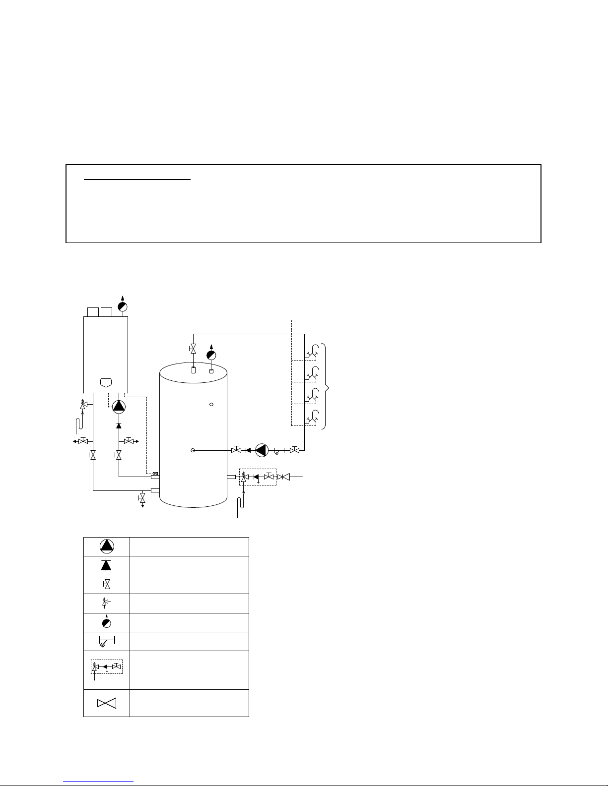
E09.012.246 Manual S-WG
38
9 THE S-WG SANITAIRY SYSTEM: INSTALLATION INSTRUCTIONS
9.1 The S-WG system
The system as a whole is set up as shown in the next two examples, the first showing a combination of one water heater and one tank, the second showing a combination of three water heaters and two tanks. Other combinations are possible as well.
SAFETY COMPONENTS
NB! The pictures in §§ 9.1.1 and 9.1.2 show examples of functional installations. The safety components as
shown in these pictures are NOT necessarily conform the applicable standards and regulations.
ALWAYS have the installation installed by a skilled installer. Safety must be added according to all applicable
standards and regulations.
9.1.1 STAND-ALONE SET-UP
The basic form of a S-WG installation is one water heater with one tank.
Shown in the picture are the principle components and connections.
Example of a combination of one water heater and one tank
PUMP
NON RETURN VALVE
VALVE
SAFETY VALVE
AUTOMATIC AIR VENT
FILTER
INLET COMBINATION
- Overflow
- Controllable return valve
- Valve
PRESSURE REGULATING
VALVE
Extra explanation:
1) Pressure relief valve (mandatory in case water pressure is too high)
2) Inlet combination with valve (mandatory)
3) Apply filter if necessary (recommended)
4) A suitable safety valve must be mounted near
the water heater (mandatory) 1
This safety valve may never be isolated from
the water heater by means of a ball valve
5) Mount remote pipe sensor as close as possible to the tank
6) Drain valve (recommended)
7) Hot and cold water mixers
A) Cold water inlet (service pipe)
B) Hot water circulation flow
C) Circulation return
1
Always apply safety components according to
all applicable standards and regulations.
1
2
3
A
B
C
4
7
A
5
6
6
6
Page 38
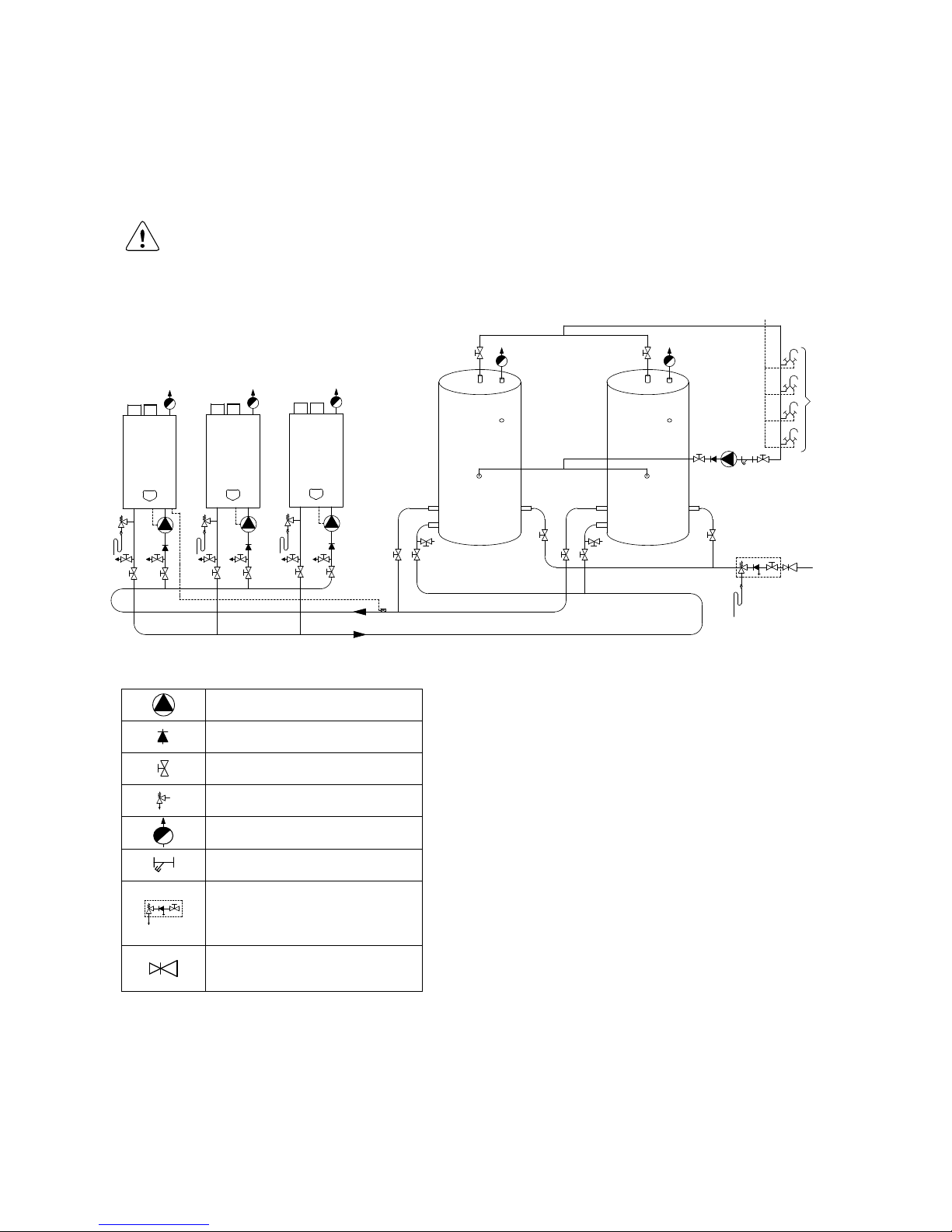
E09.012.246 Manual S-WG
39
9.1.2 CASCADE SET-UP
S-WG water heaters and tanks can be installed cascaded in a number of possible combinations cf. the instructions in the next paragraphs.
For the installation of cascaded water heaters and tanks, always consult the tables in § 9.4. All requirements concerning pipe diameters and lengths as well as pump choice are presented orderly
here.
By applying these you’ll improve both the well-functioning and the life time of your S-WG installation.
PUMP
NON RETURN VALVE
VALVE
SAFETY VALVE
AUTOMATIC AIR VENT
FILTER
INLET COMBINATION
- Overflow
- Controllable return valve
- Valve
PRESSURE REGULATING VALVE
Example of a combination of three water heaters and two tanks
Notes:
Connections on the water heater side should always be executed as drawn.
In the inlet (return) connection of the water heater no check valve is recommended.
All designs and tables in the next paragraphs go up to eight water heaters max. If needed, the water
heater control can handle up to twelve water heaters.
B
C
B
C
7
3
1
2
A
A
5
6 6
6 6 6 6 6 6
Extra explanation:
1) Pressure relief valve (mandatory in case water pressure is too high)
2) Inlet combination with valve (mandatory)
3) Apply filter if necessary (recommended)
4) A suitable safety valve must be mounted near
the water heater (mandatory) 1
This safety valve may never be isolated from
the water heater by means of a ball valve
5) Mount remote pipe sensor as close as possible to the tank
6) Drain valve (recommended)
7) Hot and cold water mixers
A) Cold water inlet (service pipe)
B) Hot water circulation flow
C) Circulation return
1
Always apply safety components according to
all applicable regulations.
Page 39

E09.012.246 Manual S-WG
40
For large capacity installations (more than two water heaters) consult STREBEL.
Page 40

E09.012.246 Manual S-WG
41
9.1.3 CONTROL GENERAL
There is no need for a sensor in the tank, because when the pump starts to run, the inlet sensor of the water
heater is measuring the water temperature of the tank.
When there is no drawing water from the tank, the inlet sensor is measuring the water temperature in the
tank.
After ending a heat demand, the pump has a post turning time.
On the control panel, the tank or hot water temperature can be set.
When a remote wall controller is connected to the wire terminal (13) and (14), the setting of the tank tem-
perature can be done with this controller (Open Therm bus), also the night or weekend reduction of tank
temperature.
During a period of no tapping, the temperature inside the tank is maintained at the Setting temperature
automatically.
A safety control stops the water heater from firing, when the temperature difference between flow and return
gets higher than allowed at the actual load (flow monitoring, ΔT function).
Parameters: the default of the parameters of the water heater control have been set for this type of tanks.
9.1.4 CASCADE CONTROL
Up to twelve water heaters can be cascaded.
One water heater has to be appointed master, the other water heaters are appointed slaves, each with
his own address in the software.
The slaves are connected with two wires to the master.
Every individual water heater has a connection for a pump.
An external temperature sensor is placed at the inlet tube of the system (S3), sensing the temperature of
the inlet water of the water heaters: the sensor has to be placed close to the connection of the tank.
At a heat demand, the master water heater controls the heat output of the slaves, on base of the mea-
sured temperature of the external sensor.
When a slave stops burning, the pump connected to this slave has a post turning time.
When one water heater in the cascade installation is burning, the fans of the other water heaters are
turning at a low speed, preventing recirculation of the flue gases.
Flow monitoring cf. § 8.4 (page 37) remains active in every separate water heater of the cascade.
Page 41
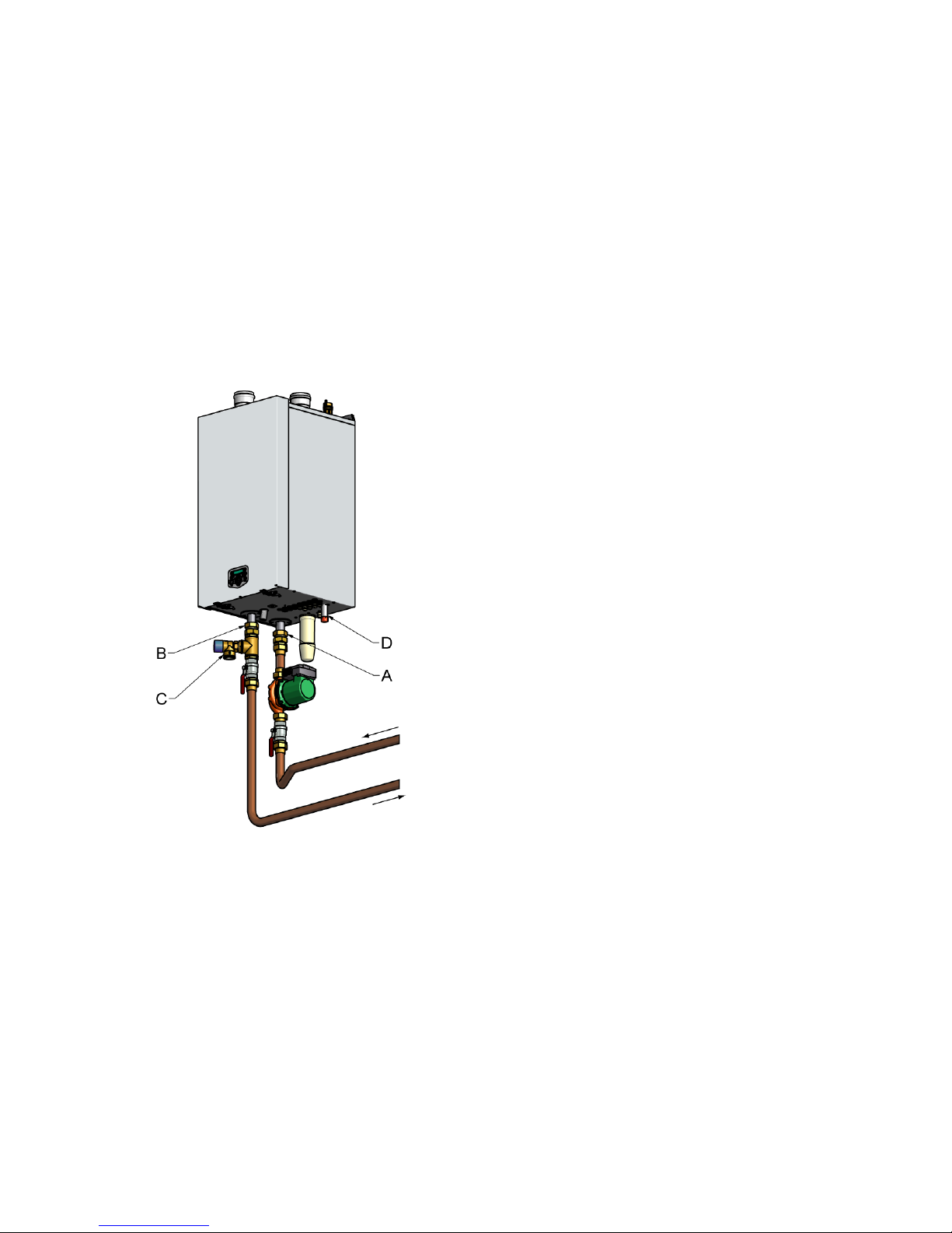
E09.012.246 Manual S-WG
42
9.2 Water heater and tank: connections and connection sizes
9.2.1 CONNECTING THE TANK TO THE WATER HEATER
Connect the pump by means of couplings and a piece of copper pipe to connection A of the water heater
(note the flow direction of the pump).
Connect the inlet of the pump to the upper of the two close above each other located connections of the
tank, labelled ‘return to water heater’.
Connect connection B of the water heater to the lower of the two close above each other located connec-
tions of the tank, labelled ‘flow from water heater’. Also make a tap point in this line at the lowest point.
WATER HEATER CONNECTIONS
A = inlet cold water
B = outlet hot water
C = overpressure safety valve
D = gas
Page 42

E09.012.246 Manual S-WG
43
9.2.2 TO CONNECT THE TANK TO YOUR DHW INSTALLATION
(see picture on next page )
Connect the fresh water supply to the single connection C, labelled ‘cold in’, opposite to A and B which
were used for connecting the water heater. For the application of inlet combination, (control) valves, etc. all
applicable regulations should be met.
Connect the DHW connection on top of the tank, labelled ‘hot out’, to your DHW installation.
Connect the recirculation line to connection F, labelled ‘circulation return’, on the side of the tank, at the
same height as inlet C.
The STREBEL tanks have the following DHW connections:
COLD IN for inlet of fresh water
HOT OUT for outlet of DHW
water heater return for connection to inlet of water heater
water heater flow for connection to outlet of water heater
CIRCULATION RETURN for recirculation of DHW from installation to tank
Besides there are connections for:
Thermometer (on side on ± ¾ of height of the tank)
Connection for T&P valve (mounted on top) according to the applicable standards and regulations. Even
if a T&P valve has to be applied, the safety at the water heater’s side, on position C ( see previous
page), should be maintained at all times!
Tank connection sizes:
Code
Connection
M / F
Remarks
300 L
450 L
750 L
A
return water heater
M
incl. reducing ring
R 2"
R 2"
R 2"
excl. reducing ring
R 1½"
R 1½"
R 1½"
B
flow water heater
M
incl. reducing ring
R 2"
R 2"
R 2"
excl. reducing ring
R 1½"
R 1½"
R 1½"
C
cold water inlet
M
incl. reducing ring
R 2"
R 2"
R 2"
excl. reducing ring
R 1½"
R 1½"
R 1½"
D
DHW outlet
M
incl. reducing ring
R 2"
R 2"
R 2"
excl. reducing ring
R 1½"
R 1½"
R 1½"
E
free connection (T&P valve)
F
incl. plug
Rp 1½"
Rp 1½"
Rp 1½"
F
circulation return
M
incl. cap
R ¾"
R ¾"
R ¾"
G
bleed valve
-
- - -
-
H
thermometer connection
F
incl. plug
Rp ½"
Rp ½"
Rp ½"
Page 43
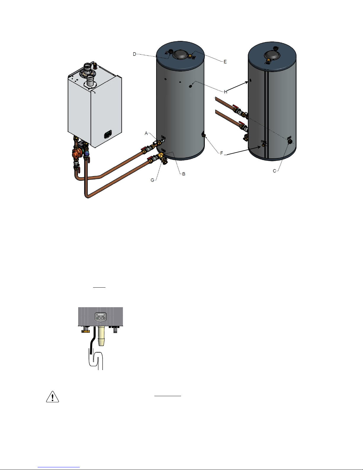
E09.012.246 Manual S-WG
44
9.2.3 CONDENSATE DRAIN CONNECTION
The condensate drain is placed at the centre at the bottom of the water heater and has a ¾ inch hose discharge.
Connect this flexible hose to the sewer system.
Use only plastic parts with the condensate drain. Metal lines are not allowed.
Blockage of this drain might damage the water heater. The drain connection is correct when the condensate can
be seen flowing away, e.g. using a funnel. Any damage that might occur, when the drain is not installed correctly, is not covered by the warranty of the water heater.
There should be an open connection between the condensate hose and the sewage system, to make sure that
any pressure difference between the two can never affect the condense water level and hence the functioning of
the water heater:
When mounting the bottom part of the siphon, before commissioning the water heater and/or after
maintenance, it must ALWAYS be completely filled with water.
This is a safety measure: the water in the siphon keeps the flue gases from entering the plant
room via the condensate drain.
Page 44
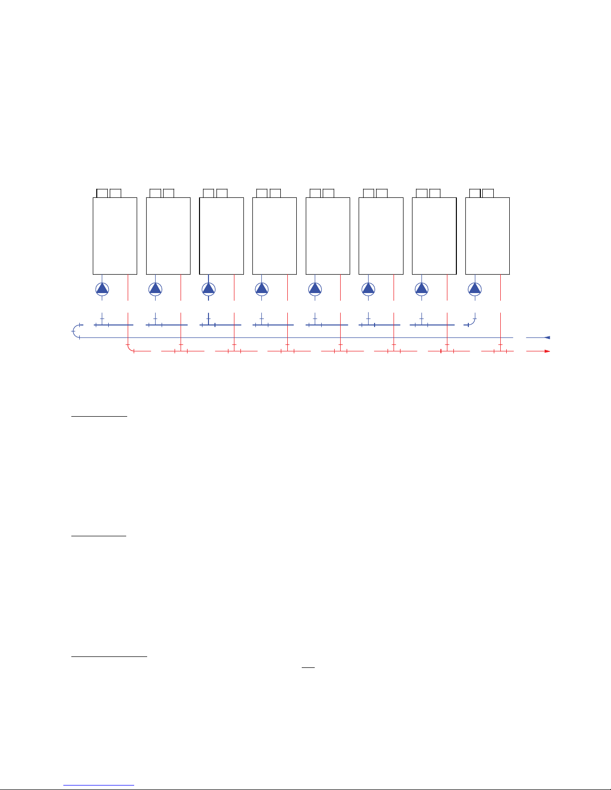
E09.012.246 Manual S-WG
45
9.3 Cascade systems: assigning pipe codes
With the tables in § 9.4 (from page 47 onwards) the diameters of the several connection pipes can be assessed,
so that there will always be sufficient flow.
For using the tables in a straightforward manner, water heaters and pipes need to be numbered, where water
heater-1 is the one that‘s situated the furthest away from the tanks. The pipe codes are set as pointed out below:
9.3.1 PIPE CODES WATER HEATER SIDE
The codes of the piping in the picture are used in the installation tables in section 9.4 to determine the right installation diameters.
Hot water out
These pipes get codes F1 to FF (where FF = F(last)) (F for flow)
The hot water connections directly to the water heaters get the next codes:
for an installation containing one water heater:
code FF (see § 9.4.1, pick the table of the corresponding water hea-ter type)
for all cascades of more than one water heater:
code F1 = Ø 54 mm (standard tube 541.5)
The (‘continuous’) hot water pipe that’s connected to this ‘water heater flow pipe’ is numbered after the corresponding water heater:
F1 at water heater-1, F2 at water heater-2, etc.
Cold water in
These pipes get codes R1 to RR (where RR = R(last)) (R for return)
The return connections directly to the water heaters get the next codes:
for an installation containing one water heater:
code RR (see § 9.4.1, pick the table of the corresponding water heater type)
for all cascades of more than one water heater:
code R1 = Ø 54 mm (standard tube 541.5)
The (‘continuous’) return pipe that’s connected to this ‘water heater return pipe’ is numbered ‘reversely’ to the
corresponding water heater:
R1 at water heater-last, R2 at water heater-last but one, etc.
Main connections:
- The main connections from cascade to tank(s) are not called F(number-last) and R(number-last) but FF and
RR.
- For every type of cascade F1=R1, F2=R2, …, FF=RR.
On the next page the procedure will be summarized
F1R1F1R1F1R1F1R1
R2 R1R3
RR
FF
F5F3 F4
R1F1
R4
F2
R1
RR R5
F1
F1
R1 F1
R6
F6
R1 F1
F7
R7
1 2 3 4 5 6 7 8
Page 45
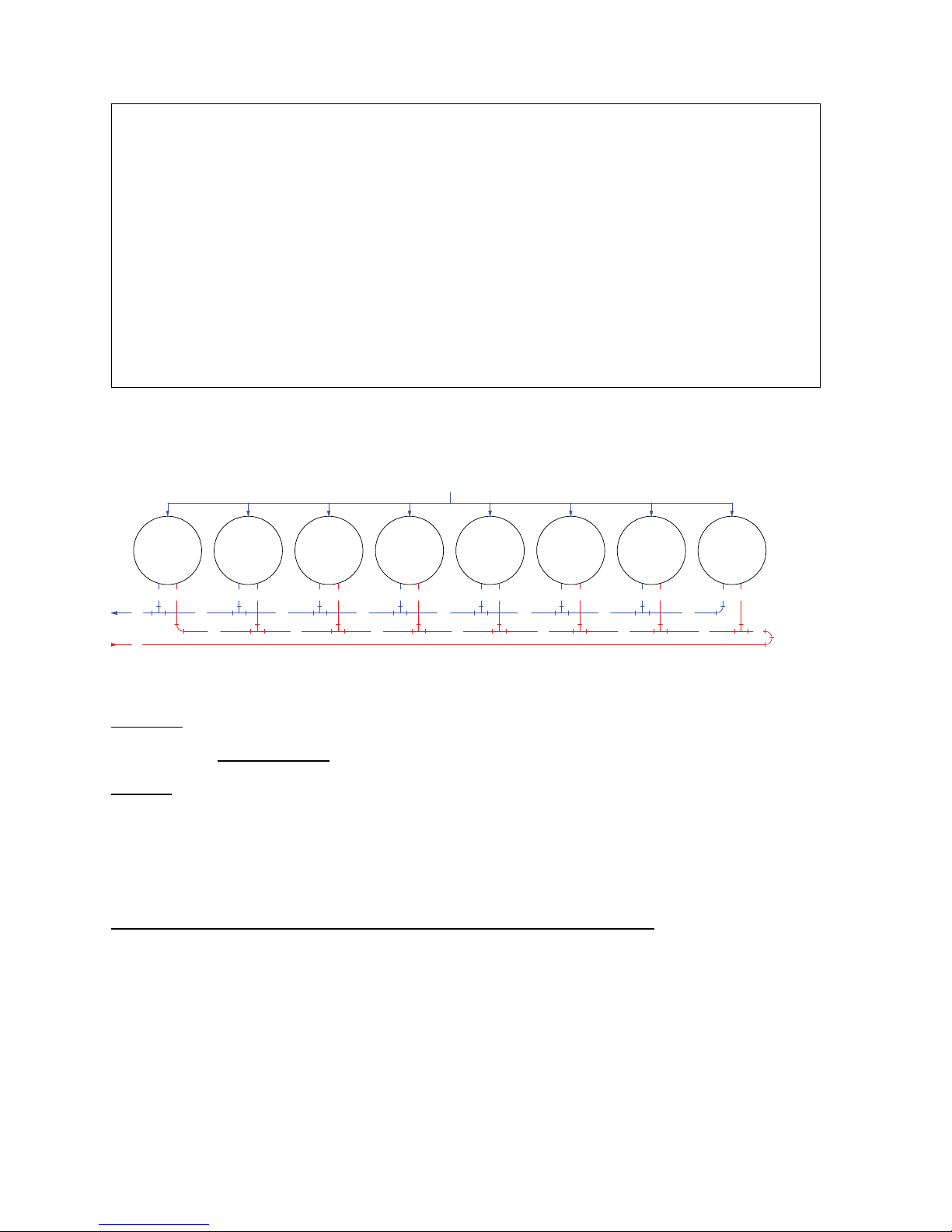
E09.012.246 Manual S-WG
46
9.3.2 PIPE CODES AT THE TANKS’ SIDE
The codes of the piping in the picture are used in the installation tables in section 9.4 to determine the right installation diameters.
Numbering
Tank numbering may be useful to install flow and return connections in the right way, but doesn’t affect pipe
diameters. Only numbers of tanks and water heater type do (see tables § 9.4.2).
Encoding
Tank connections: A1 and B1 (entrance and exit). The values are found in the tank tables (§ 9.4.2)
Pipes between these connections: FF and RR, values from the water heater tables (§ 9.4.1).
For a given cascade, A1 equals B1.
9.3.3 EQUIVALENT LENGTH
Piping between (cascaded) water heaters and one or more tanks. Equivalent length.
Piping connecting the water heaters’ cascade with the tanks may not be too long, and moreover, every extra
component, such as bends and the like, contributes to the so-called ‘equivalent length’, see table ‘Equivalent
lengths’ in § 9.4.3 on page 50.
ELABORATED EXAMPLES
At the end of this chapter, in § 9.5.4, three elaborated examples will be given demonstrating how to apply the
tables and values given in §§ 9.4 and 9.5.
FF
B1A1 B1A1
RR
FF
A1 B1
RR RR
FF
A1B1
FF
B1A1
RR
B1 A1
RR
FFFF
1 2 3 4 5 6 7
B1
RR
A1
FF
A1B1
8
RR
FF
COLDIN
RR
FF
COLD WATER IN (SERVICE PIPE)
SUMMARY ENCODING PIPES WATER HEATER SIDE:
Assigning codes to a one water heater installation:
- There’s only one flow pipe, encoded FF, and one return pipe, encoded RR. For the right diameters see § 9.4.1, pick the table of the corresponding water heater type.
Assigning codes to cascades: two or more water heaters to connect:
- First number the water heaters: water heater-1 is the one that‘s situated the furthest away from
the tank(s).
- Connections directly to the water heaters: F1 = R1 = 541,5 (mmmm)
- Number the horizontal flow pipes between water heaters: from F1 at water heater-1 to FF at
water heater-number-last.
- Number the horizontal return pipes between water heaters ‘reversely’: from R1 at water heaternumber-last to RR at water heater-1.
Page 46
E09.012.246 Manual S-WG
47
9.4 Connection component tables – diameters and lengths
General remark: diameters may at any time be chosen LARGER than specified in the tables, but never
SMALLER. Flow must remain guaranteed.
The pipe tables in this section are numbered after capacity:
Water heater tables WH-80, WH-100 etc. up to WH-180 and tank headers T-80, T-100 etc. up to T-180.
9.4.1 WATER MANIFOLDS
Numbering:
- Water heater-1 is the one that is situated the furthest away from the tanks
- For the hot water flow pipes start numbering (F1) at water heater-1
- For the cold water return pipes start numbering (R1) at water heater-nr. last
The figures in the tables refer to diameterwall thickness (mmmm) of the corresponding pipe
S-WG80
Nr. of cascaded
water heaters
FF/RR
F1/R1
F2/R2
F3/R3
F4/R4
F5/R5
F6/R6
F7/R7
1
421.4
---
---
---
---
---
---
---
2
671.9
541.5
---
---
---
---
---
---
3
802.1
541.5
671.9
---
---
---
---
---
4
802.1
541.5
671.9
802.1
---
---
---
---
5
932.3
541.5
671.9
802.1
802.1
---
---
---
6
1062.5
541.5
671.9
802.1
802.1
932.3
---
---
7
1062.5
541.5
671.9
802.1
802.1
932.3
1062.5
---
8
1332.8
541.5
671.9
802.1
802.1
932.3
1062.5
1062.5
table WH-80
S-WG100
Nr. of cascaded
water heaters
FF/RR
F1/R1
F2/R2
F3/R3
F4/R4
F5/R5
F6/R6
F7/R7
1
541.5
---
---
---
---
---
---
---
2
671.9
541.5
---
---
---
---
---
---
3
802.1
541.5
671.9
---
---
---
---
---
4
932.3
541.5
671.9
802.1
---
---
---
---
5
1062.5
541.5
671.9
802.1
932.3
---
---
---
6
1062.5
541.5
671.9
802.1
932.3
1062.5
---
---
7
1332.8
541.5
671.9
802.1
932.3
1062.5
1062.5
---
8
1332.8
541.5
671.9
802.1
932.3
1062.5
1062.5
1332.8
table WH-100
S-WG120
Nr. of cascaded
water heaters
FF/RR
F1/R1
F2/R2
F3/R3
F4/R4
F5/R5
F6/R6
F7/R7
1
541.5
---
---
---
---
---
---
---
2
802.1
541.5
---
---
---
---
---
---
3
932.3
541.5
802.1
---
---
---
---
---
4
1062.5
541.5
802.1
932.3
---
---
---
---
5
1332.8
541.5
802.1
932.3
1062.5
---
---
---
6
1332.8
541.5
802.1
932.3
1062.5
1332.8
---
---
7
1332.8
541.5
802.1
932.3
1062.5
1332.8
1332.8
---
8
1593.0
541.5
802.1
932.3
1062.5
1332.8
1332.8
1332.8
table WH-120
to be continued
Page 47
E09.012.246 Manual S-WG
48
(Water manifolds continued (§ 9.4.1))
S-WG150
Nr. of cascaded
water heaters
FF/RR
F1/R1
F2/R2
F3/R3
F4/R4
F5/R5
F6/R6
F7/R7
1
541.5
---
---
---
---
---
---
---
2
802.1
541.5
---
---
---
---
---
---
3
932.3
541.5
802.1
---
---
---
---
---
4
1062.5
541.5
802.1
932.3
---
---
---
---
5
1332.8
541.5
802.1
932.3
1062.5
---
---
---
6
1332.8
541.5
802.1
932.3
1062.5
1332.8
---
---
7
1593.0
541.5
802.1
932.3
1062.5
1332.8
1332.8
---
8
1593.0
541.5
802.1
932.3
1062.5
1332.8
1332.8
1593.0
table WH-150
S-WG180
Nr. of cascaded
water heaters
FF/RR
F1/R1
F2/R2
F3/R3
F4/R4
F5/R5
F6/R6
F7/R7
1
671.9
---
---
---
---
---
---
---
2
932.3
541.5
---
---
---
---
---
---
3
1062.5
541.5
932.3
---
---
---
---
---
4
1332.8
541.5
932.3
1062.5
---
---
---
---
5
1332.8
541.5
932.3
1062.5
1332.8
---
---
---
6
1593.0
541.5
932.3
1062.5
1332.8
1332.8
---
---
7
1593.0
541.5
932.3
1062.5
1332.8
1332.8
1593.0
---
8
Di>160
541.5
932.3
1062.5
1332.8
1332.8
1593.0
1593.0
table WH-180
9.4.2 TANK HEADERS
The numbers in the tables are diameter wall thickness (mm mm) of the corresponding pipe
S-WG80
Pipe diameter A1/B1 to the water tanks
Nr. of cascaded
water heaters
1 tank
2 tanks
3 tanks
4 tanks
5 tanks
6 tanks
7 tanks
8 tanks
1
421.4
351.3
281.2
221,1
221.1
221.1
221.1
221.1
2
671.9
421.4
351.3
351,3
281.2
281.2
281.2
221.1
3
802.1
541.5
421.4
421,4
351.3
351.3
281.2
281.2
4
802.1
671.9
541.5
421,4
421.4
351.3
351.3
351.3
5
932.3
671.9
541.5
541,5
421.4
421.4
351.3
351.3
6
1062.5
802.1
671.9
541,5
541.5
421.4
421.4
421.4
7
1062.5
802.1
671.9
541,5
541.5
541.5
421.4
421.4
8
1332.8
802.1
671.9
671,9
541.5
541.5
541.5
421.4
table T-80
S-WG100
Pipe diameter A1/B1 to the water tanks
Nr. of cascaded
water heaters
1 tank
2 tanks
3 tanks
4 tanks
5 tanks
6 tanks
7 tanks
8 tanks
1
541.5
351.3
281.2
281,2
221.1
221.1
221.1
221.1
2
671.9
541.5
421.4
351,3
351.3
281.2
281.2
281.2
3
802.1
541.5
541.5
421,4
351.3
351.3
351.3
281.2
4
932.3
671.9
541.5
541,5
421.4
421.4
351.3
351.3
5
1062.5
802.1
671.9
541,5
541.5
421.4
421.4
421.4
6
1062.5
802.1
671.9
541,5
541.5
541.5
421.4
421.4
7
1332.8
932.3
671.9
671,9
541.5
541.5
541.5
421.4
8
1332.8
932.3
802.1
671,9
671.9
541.5
541.5
541.5
table T-100
to be continued
Page 48

E09.012.246 Manual S-WG
49
(Tank headers continued (§ 9.4.2))
S-WG120
Pipe diameter A1/B1 to the water tanks
Nr. of cascaded
water heaters
1 tank
2 tanks
3 tanks
4 tanks
5 tanks
6 tanks
7 tanks
8 tanks
1
541.5
421.4
351.3
281,2
281.2
221.1
221.1
221.1
2
802.1
541.5
421.4
421,4
351.3
351.3
281.2
281.2
3
932.3
671.9
541.5
541,5
421.4
421.4
351.3
351.3
4
1062.5
802.1
671.9
541,5
541.5
421.4
421.4
421.4
5
1332.8
802.1
671.9
671,9
541.5
541.5
541.5
421.4
6
1332.8
932.3
802.1
671,9
671.9
541.5
541.5
541.5
7
1332.8
1062.5
802.1
671,9
671.9
671.9
541.5
541.5
8
1593.0
1062.5
932.3
802,1
671.9
671.9
541.5
541.5
table T-120
S-WG150
Pipe diameter A1/B1 to the water tanks
Nr. of cascaded
water heaters
1 tank
2 tanks
3 tanks
4 tanks
5 tanks
6 tanks
7 tanks
8 tanks
1
541.5
421.4
351.3
281,2
281.2
281.2
221.1
221.1
2
802.1
541.5
541.5
421,4
351.3
351.3
351.3
281.2
3
932.3
671.9
541.5
541,5
421.4
421.4
421.4
351.3
4
1062.5
802.1
671.9
541,5
541.5
541.5
421.4
421.4
5
1332.8
932.3
802.1
671,9
541.5
541.5
541.5
541.5
6
1332.8
932.3
802.1
671,9
671.9
541.5
541.5
541.5
7
1593.0
1062.5
932.3
802,1
671.9
671.9
541.5
541.5
8
1593.0
1062.5
932.3
802,1
802.1
671.9
671.9
541.5
table T-150
S-WG180
Pipe diameter A1/B1 to the water tanks
Nr. of cascaded
water heaters
1 tank
2 tanks
3 tanks
4 tanks
5 tanks
6 tanks
7 tanks
8 tanks
1
671.9
541.5
421.4
351,3
351.3
281.2
281.2
281.2
2
932.3
671.9
541.5
541,5
421.4
421.4
351.3
351.3
3
1062.5
802.1
671.9
541,5
541.5
541.5
421.4
421.4
4
1332.8
932.3
802.1
671,9
671.9
541.5
541.5
541.5
5
1593.0
1062.5
802.1
802,1
671.9
671.9
541.5
541.5
6
1593.0
1062.5
932.3
802,1
802.1
671.9
671.9
541.5
7
Di>160
1332.8
1062.5
932,3
802.1
671.9
671.9
671.9
8
Di>160
1332.8
1062.5
932,3
802.1
802.1
671.9
671.9
table T-180
Page 49
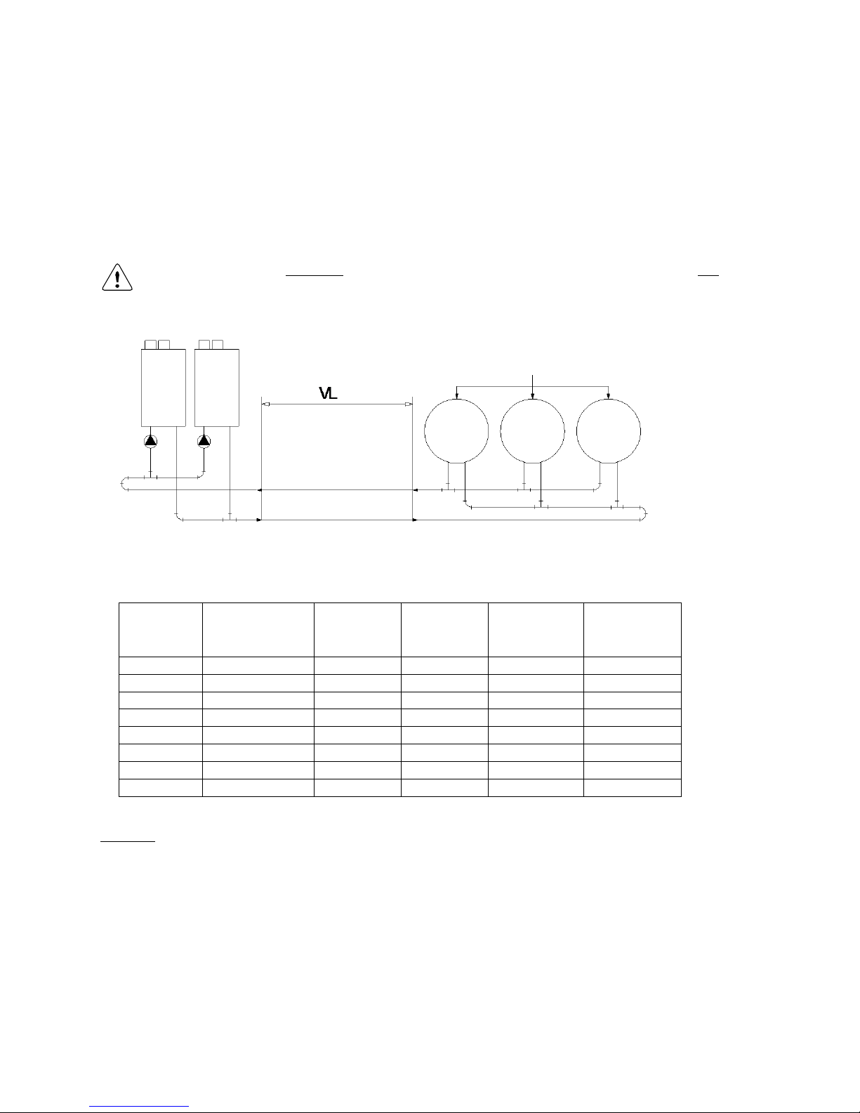
E09.012.246 Manual S-WG
50
9.4.3 INTERCONNECTING PIPES – DIAMETERS AND EQUIVALENT LENGTH
When the water heaters and tanks are separated over some distance, the interconnecting pipes may only have a
certain maximum length, dependent of the number of bends and the like components. For every applied component a so-called ‘equivalent length’ is deducted from the total allowed.
The meaning of the connection ‘VL’ can be seen in the drawing below.
The diameter of this connection VL should meet at least the specified pipe diameter FF/RR. For this pipe connection the maximum straight length of flow and return part added * has been specified in the table below.
* The real available maximum distance VL between water heaters and tanks is therefore half of the
length specified in the table!
Drawing, explaining pipe connection ‘VL’:
Each component that’s added to the straight pipes is contributing to the total resistance, and will therefore cause
a necessary reduction of straight length. The table contains a number of commonly used components and their
equivalent length:
Copper
pipe
diameter
Maximum
straight length
flow + return
equiv. length
90° elbow
R=0.5D
equiv. length
90° elbow
R=1.0D
equiv. length
45° bend
R=1.0D
fully
ported
ball valve
RR/FF
m
m/elbow
m/elbow
m/bend
m/valve
541.5
24.2
2.8
1.0
0.6
0.4
671.9
26.1
3.3
1.1
0.7
0.5
802.1
28.5
3.8
1.3
0.8
0.6
932.3
31.9
4.6
1.6
0.9
0.7
1062.5
36.7
5.7
2.0
1.1
0.9
1332.8
44.3
7.5
2.6
1.5
1.1
1593.0
58.2
10.8
3.8
2.2
1.6
table EL
Example:
Suppose, for a project the diameter FF/RR has been specified the value 1062.5, so the maximum allowed
straight length is 36.7 m (see table).
In the connection is added
- 4 bend 90°, R=0.5D
- 2 fully ported ball valve
This gives a reduced allowed straight length of:
36.7 ( 45.7 ) ( 20.9 ) = 12.1 m
With this component configuration one may only use 12.1 m straight length.
The distance between water heater main connections and tank main connections in this example is therefore
~6 m at max.
Page 50
E09.012.246 Manual S-WG
51
9.5 Pump choice and pump control
Pump choice is of very great importance, because, in combination with the system’s total resistance, it sets the
water velocity in water heater and pipes. The right water velocity is essential for correct functioning and a long
life time of the system.
9.5.1 PUMP CHOICE
Select the pump for your S-WG-installation using the following tables, by looking up, in the table that relates to
the S-WG water heater type you installed, the applied combination of numbers of cascaded water heaters and
tanks. 1
P1 = Wilo TOP Z 25/10 (1.5")
P2 = Grundfos UPS 32-100N
S-WG 80
Number of tanks
cascaded
units
1 tank
2 tanks
3 tanks
4 tanks
5 tanks
6 tanks
7 tanks
8 tanks
1
P1
P1
P1
P1
P1
P1
P1
P1 2 P2
P1
P1
P1
P1
P1
P1
P1 3 x
P1
P1
P1
P1
P1
P1
P1 4 x
P2
P1
P1
P1
P1
P1
P1
5
x
P2
P1
P1
P1
P1
P1
P1
6
x x P2
P1
P1
P1
P1
P1 7 x x P2
P1
P1
P1
P1
P1 8 x x P2
P2
P1
P1
P1
P1
P2 = Grundfos UPS 32-100N
P4 = Wilo TOP Z 30/10 (2") when not available P4 is replaced by P2
S-WG100
Number of tanks
Nr. of cascaded
water heaters
1 tank
2 tanks
3 tanks
4 tanks
5 tanks
6 tanks
7 tanks
8 tanks
1
P4
P4
P4
P4
P4
P4
P4
P4
2
P2
P4
P4
P4
P4
P4
P4
P4 3 x
P4
P4
P4
P4
P4
P4
P4 4 x
P2
P4
P4
P4
P4
P4
P4 5 x x P4
P4
P4
P4
P4
P4 6 x x P2
P4
P4
P4
P4
P4 7 x x P2
P4
P4
P4
P4
P4
8
x x x
P2
P4
P4
P4
P4
P2 = Grundfos UPS 32-100N
S-WG120
Number of tanks
Nr. of cascaded
water heaters
1 tank
2 tanks
3 tanks
4 tanks
5 tanks
6 tanks
7 tanks
8 tanks
1
P2
P2
P2
P2
P2
P2
P2
P2 2 x
P2
P2
P2
P2
P2
P2
P2 3 x x P2
P2
P2
P2
P2
P2 4 x x P2
P2
P2
P2
P2
P2
5
x x x
P2
P2
P2
P2
P2
6
x x x x P2
P2
P2
P2 7 x x x x P2
P2
P2
P2 8 x x x x x
P2
P2
P2
Page 51
E09.012.246 Manual S-WG
52
P2 = Grundfos UPS 32-100N
S-WG150
Number of tanks
Nr. of cascaded
water heaters
1 tank
2 tanks
3 tanks
4 tanks
5 tanks
6 tanks
7 tanks
8 tanks
1
P2
P2
P2
P2
P2
P2
P2
P2 2 x x P2
P2
P2
P2
P2
P2 3 x x x
P2
P2
P2
P2
P2 4 x x x x P2
P2
P2
P2 5 x x x x x
P2
P2
P2
6
x x x x x x x
P2
7
x x x x x x x x 8
x x x x x x x
x
P3 = UPS 40-120 FB
S-WG180
Number of tanks
cascaded
units
1 tank
2 tanks
3 tanks
4 tanks
5 tanks
6 tanks
7 tanks
8 tanks
1
P3
P3
P3
P3
P3
P3
P3
P3 2 x
P3
P3
P3
P3
P3
P3
P3
3
x x P3
P3
P3
P3
P3
P3
4
x x x
P3
P3
P3
P3
P3 5 x x x x P3
P3
P3
P3 6 x x x x x
P3
P3
P3 7 x x x x x x P3
P3
8
x x x x x x x
P3
1
NB! An x in the pump tables doesn’t necessarily mean that the corresponding installation cannot be built. If it
can, it will need specific design effort and pump choice. Please consult STREBEL for advice.
STREBEL part numbers
Water heater
Pump
Part nr.
S-WG 80
Pump Top-Z 25/10
E09.000.064
S-WG 100
Pump Top-Z 30/10
E09.000.065
S-WG 100/120/150
DHW pump UPS 32-100N
E09.000.112
S-WG 180
DHW pump UPS 40-120 FB
E09.000.115
9.5.2 NOMINAL FLOW PER WATER HEATER TYPE
Water heater
Flow [m3/h]
S-WG 80
S-WG 100
S-WG 120
S-WG 150
S-WG 180
3.97
4.77
6.36
7.15
8.89
9.5.3 PUMP CONTROL
The applied pump must be controlled by the S-WG water heater control. If, for any reason, an external
pump control is applied without written approval of STREBEL, then the complete warranty on the S-WG
water heater and all delivered parts will become invalid.
Page 52

E09.012.246 Manual S-WG
53
9.5.4 PUMP: MAXIMUM ELECTRICAL POWER
General
- The inrush current of a conventional pump is approximately 2½ x its nominal current.
- The maximum current, that the relay on the PCB can switch, is 5 A.
The conclusion from this is that nominal currents of pumps, controlled by the PCB, may not exceed 2 A.
S-WG pump.
The nominal current of the pump must be equal to or lower than 2 A.
All pumps of § 9.5.1 fulfil this condition.
Warning (EC pumps):
In case of using an electronic commutating pump, the relays 1, 2 or 3 may not be used for the power connection,
because of the inrush current of the electronics of the pump.
Directly connect the pump to the mains of the water heater and use the cable kit from STREBEL.
Control connections of an EC pump can be established in several ways, set by parameter P5BN.
See § 11.2.5 on page 92.
Page 53
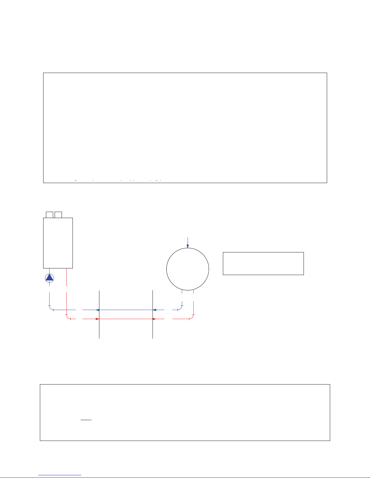
E09.012.246 Manual S-WG
54
9.6 Elaborated examples
To work out the examples in this section, the rules of page 46 are given again:
9.6.1 ONE S-WG120 WATER HEATER WITH ONE 450-LITRES TANK
Water heater and tank connections:
For this system rule 1 must be applied, so only one pipe size is needed.
No numbering of water heaters, tanks and connections is required.
From table WH-120: for 1 water heater is FF = RR = 541.5 [mmmm]
From table T-120: for 1 tank is A1 = B1 = 541.5 [mmmm]
For this system pipes sized at least 541.5 [mmmm] are required for all connections.
Equivalent length:
From table EL:
The maximum total length of flow and return pipes 541.5 [mmmm] is 24.2 m.
So when 541.5 [mmmm] is applied, the physical distance between water heaters and tanks may be half of
this,
so ~ 12 m, at max. In case bends and/or valves are used, this distance becomes less than 12 m. Use the table.
tank 450 L
boiler SWG120
FF
FF
RR
RR
1
RR
FF
KOUDIN
1
B1 A1
1. Assigning codes to a one water heater installation:
There’s only one flow pipe, encoded FF, and one return pipe, encoded RR. For the right diameters
see § 9.4.1, pick the table of the corresponding water heater type.
2. Assigning codes to cascades: two or more water heaters to connect:
First number the water heaters: water heater-1 is the one that‘s situated the furthest away from the
tank(s).
Connections directly to the water heaters: F1 = R1 = 541.5 (mmmm)
Number the horizontal flow pipes between water heaters: from F1 at water heater-1 to FF at water
heater-number-last.
Number the horizontal return pipes between water heaters ‘reversely’: from R1 at water heater-
number-last to RR at water heater-1.
3. Assigning codes to tank connections:
- Tank connections: A1 and B1 (entrance and exit). The values are found in the tank tables (§ 9.4.2)
- Pipes between these connections: FF and RR, values from the water heater tables (§ 9.4.1).
Example 1
COLD IN
Page 54
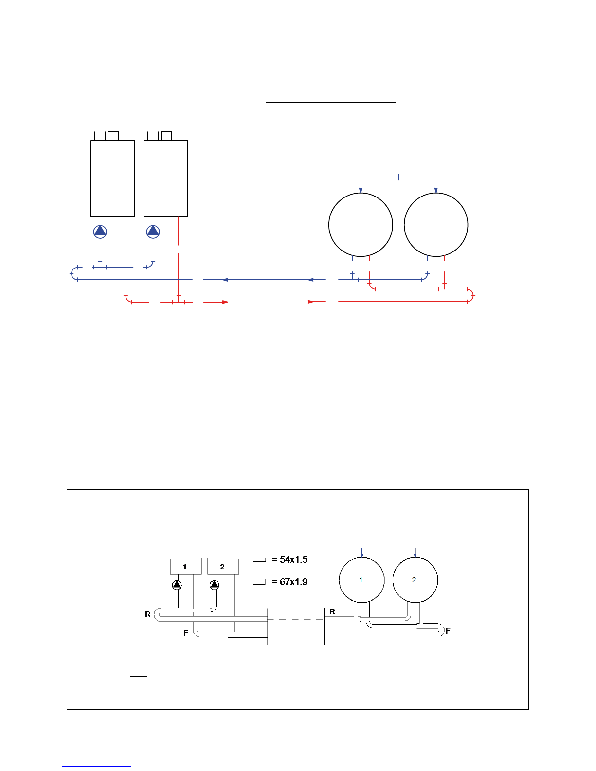
E09.012.246 Manual S-WG
55
9.6.2 TWO S-WG100 WATER HEATERS WITH TWO 450-LITRES TANKS
Water heater connections, assigning codes:
For this system rule 2 must be applied.
Number the water heaters: water heater-1 is the water heater furthest from the tank(s), see picture.
Number de connection pipes directly connected to the water heaters: F1 en R1, see picture.
Number de horizontal connection pipes:
- flow pipes starting at water heater-1: F1 t/m FF (here only an F1 and an FF), see picture.
- return pipes starting at water heater-last (= water heater-2): R1 t/m RR (same remark), see picture.
Pipe sizes, water heater side:
From table WH-100, 2nd row:
- All pipes F1 and R1 in the picture must measure at least 541,5 [mmmm] (column F1/R1)
- The pipes FF and RR must measure 671.9 [mmmm] (column FF/RR).
Tank connections:
From table T-100, 2nd row: for 2 tanks A1 = B1 = 541.5 [mmmm] is sufficient.
So for this system pipes sized at least 541.5 [mmmm] are to be applied for all connections directly on water
heaters and tanks, and pipes sized at least 671.9 [mmmm] for the flow and return connections between
them.
Equivalent length:
From table EL:
The maximum total length of flow and return pipes 671.9 [mmmm] is 26.1 m.
So when 671.9 [mmmm] is applied, the physical distance between water heaters and tanks may be half of
this, so ~ 13 m, at max. In case bends and/or valves are used, this distance becomes less than 13 m. Use the
table.
2 boilers
S-WG100
2 tanks
450 L
F1R1F1R1
R1
FFF1
RR
RR
1 2
FF
B1 A1 B1 A1
RR
FF
KOUDIN
1 2
Example 2
COLD IN
Page 55
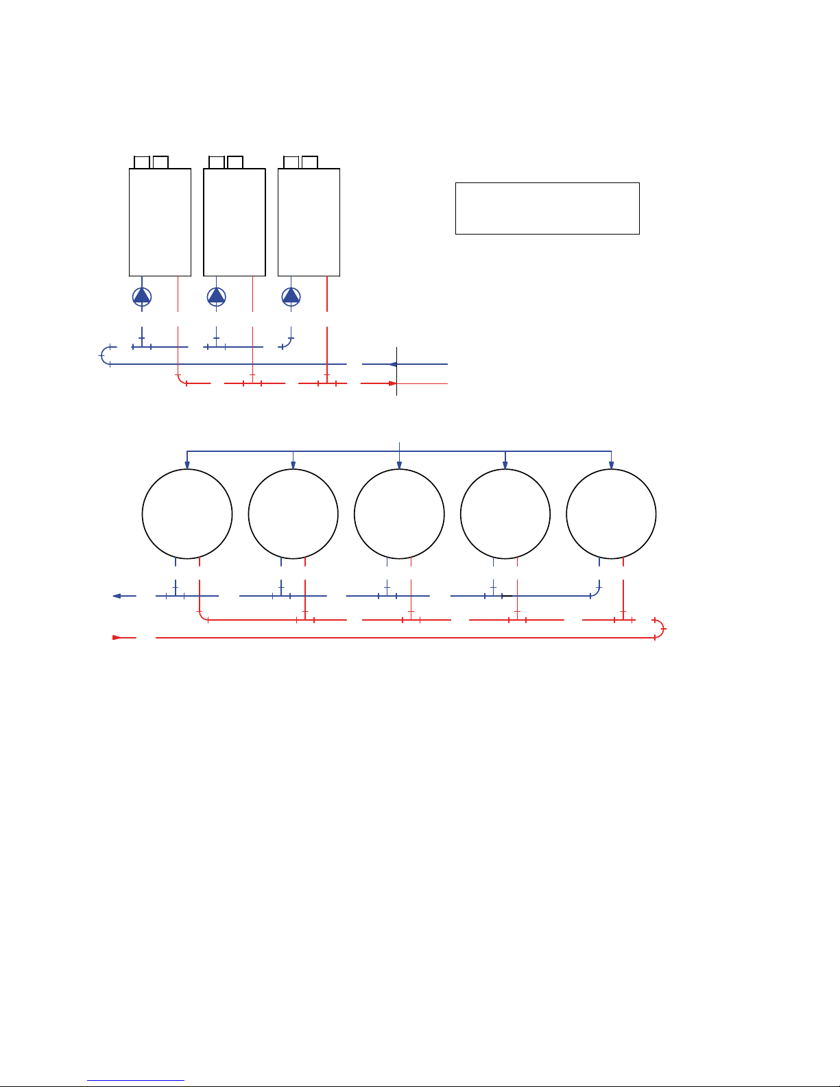
E09.012.246 Manual S-WG
56
9.6.3 THREE S-WG180 WATER HEATERS WITH FIVE 750-LITRES TANKS
Water heater connections, assigning codes:
For this system rule 2 must be applied.
Number the water heaters: water heater-1 is the water heater furthest from the tank(s), see picture.
Number de connection pipes directly connected to the water heaters: F1 en R1, see picture.
Number de horizontal connection pipes:
- flow pipes starting at water heater-1: F1, F2, FF, see picture.
- return pipes starting at water heater-last (= water heater-3): R1, R2, RR, see picture.
Pipe sizes, water heater side:
From table WH-180, 3rd row:
- All pipes F1 and R1 in the picture must measure at least 541,5 [mmmm] (column F1/R1)
- The pipes F2 and R2 must measure 932.3 [mmmm] (column F2/R2).
- The pipes FF and RR must measure 1062.5 [mmmm] (column FF/RR).
-
Tank connections:
From table T-180, 3rd row: for 5 tanks A1 = B1 = 541.5 [mmmm] is sufficient again.
Resulting set-up see next page
5 tanks
750 L
FF
B1 A1 B1 A1
RR
FF
A1B1
RR RR
FF
A1B1
FF
B1 A1
RR
FF
1 2 3 4 5
KOUDIN
3 ketels
S-WG180
F1R1F1R1R1
R2 R1
RR
FFF2F1
RR
F1
1 2 3
RR
FF
tanks
Example 3
COLD IN
Page 56
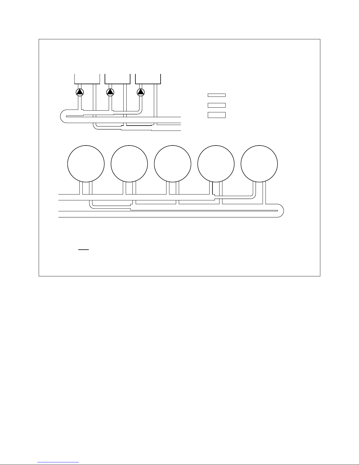
E09.012.246 Manual S-WG
57
So for this system, sizes of at least 541.5 [mmmm] are to be applied for all pipes directly connected to the
water heaters and tanks, and pipes sized at least 1062.5 [mmmm] for the flow and return connections between the cascaded water heaters and the tanks. The pipes F2 and R2 must be at least 932.3 [mmmm].
Equivalent length:
From table EL:
The maximum total length of flow and return pipes 1062,5 [mmmm] is 36,7 m.
So when 1062,5 [mmmm] is applied, the physical distance between water heaters and tanks may be half of
this,
so ~ 18 m, at max. In case bends and/or valves are used, this distance becomes less than 18 m. Use the table.
1 2 3
= 54 x 1.5
= 93 x 2.3
= 106 x 2.5
1 2 3 4 5
R
F
R
F
Page 57
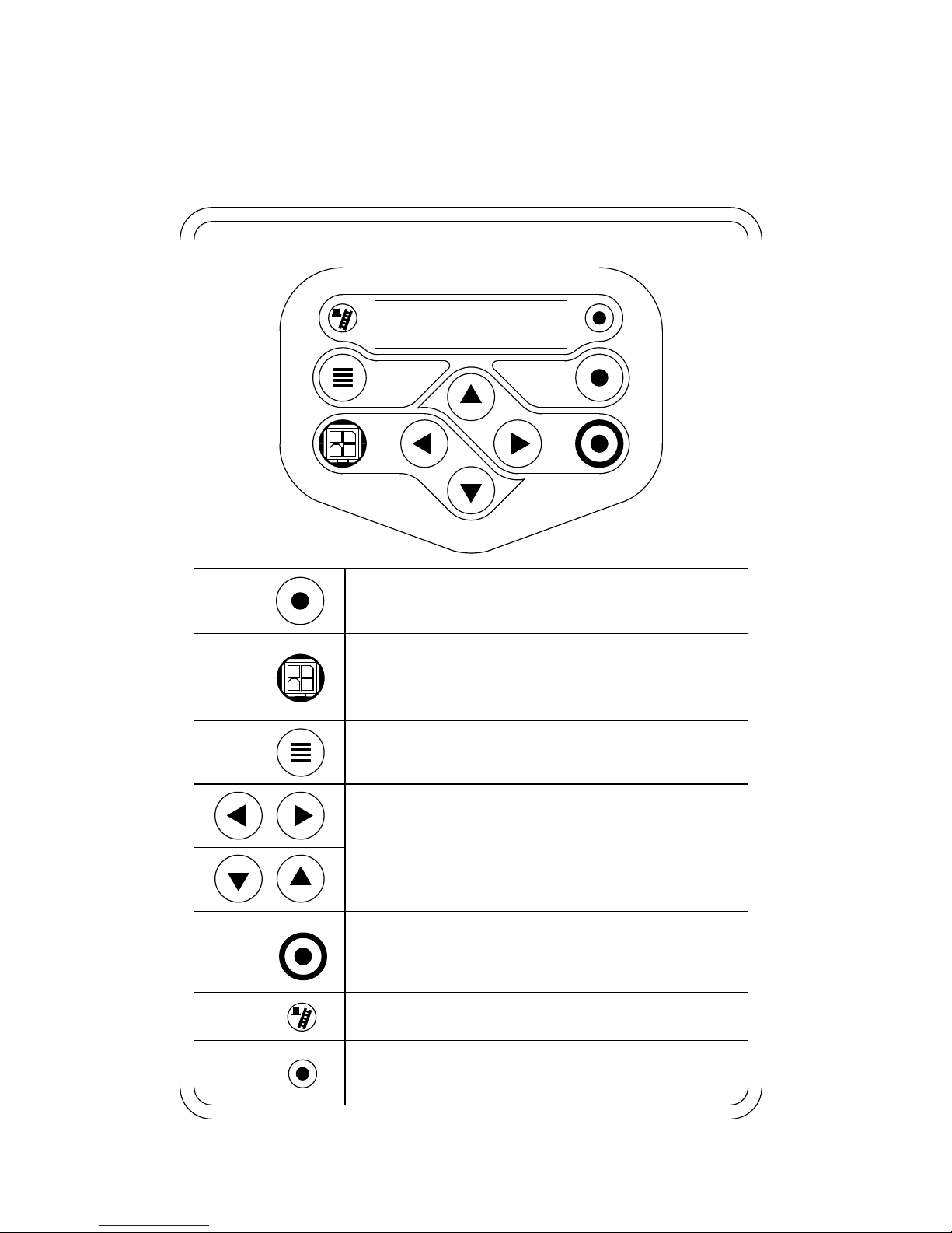
E09.012.246 Manual S-WG
58
10 USER INTERFACE
10.1 Control panel / Display unit
DISPLAY
2 rows / each 20 characters
MENU
ON/OFF
RESET
ENTER
SERVICE
COMM. PORT
ON/OFF
RESET
ENTER
Press and hold for 6 seconds to switch water heater on/off.
Is also used as RESET button and ENTER button when programming.
Connector for connecting computer cable
Buttons can be pushed to open menu.
[ hold for 1 second ]
Buttons to toggle through measured temperatures.
These are also used for navigating through the menus and
used for changing values.
Button to activate service function.
[ hold for 3 seconds ]
Schornsteinfeger function (only for Germany).
Light: will light up when controller sees good flame signal.
Lights when burner is burning.
SERVICE
MENU
COMM. PORT
Page 58
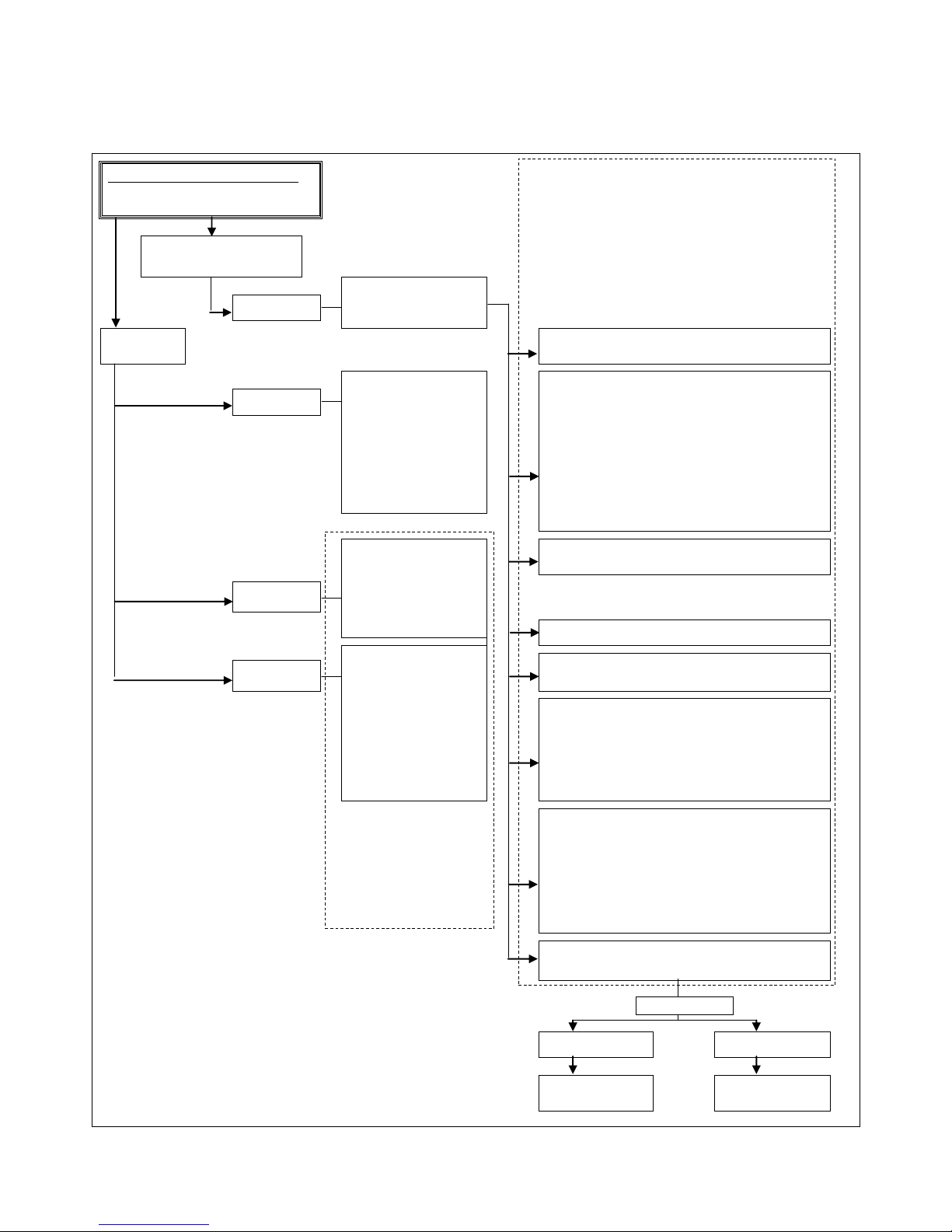
E09.012.246 Manual S-WG
59
10.2 Control panel menu structure
BASE SCREEN : (appears during operation)
WTRHTR : No demand / Standby / burning
> > > : 1 1 8 ° C ( 1 2 5 ° C )
CONFIRMATION CHANGE
When changes are being made in the menus within this dashed rectangle,
the user presses ENTER to confirm the changes.
To prevent customers making changes by accident the following happens
when changes are made:
Step 1: The user presses "ENTER" to confirm the change made
or [MENU] to leave the menu without changes.
HINT: First programme all changes planned, then only press
[ENTER]
Step 2: The display asks the user to be sure to make these changes. The
user can cancel and confirm by using the left and right arrows.
CANCEL = ◄ CONFIRM = ►
press [ON/OFF] for 3 s. to
programme in standby mode
By pressing (◄ ►) one can
toggle though the available
menus.
press: MENU
view data
"TIME/DATE/DAY" menu
In this menu one can set the time and the date.
"MONITOR" screens
One can toggle through the
measured values and status of
the heater.
Pressing "ON/OFF, RESET,
ENTER" briefly will cause the
display to go back to the base
menu.
When no button has been
pressed for 3 minutes the display
will automatically go to the BASE
DISPLAY.
(This period can be set by a
parameter)
"SETPOINT" menu
In this menu one can change temperature settings without the need for
a password.
- Hot water set point
Calorifier or water heater (depends on heater type) tank temperature
- Hot water reduced
The amount of degrees diff. relative to "Hot water set point" during night reduction.
- Local set point water heater
The temperature of the hot water supply from the DHW appliance to the tank is set here.
press: ◄ ►
Display shows 2x20 digit message for 3 seconds.
Message can be set in parameters.
example:
Company name
City, Country
"PROGRAM" menu
In this menu one can set the DHW and Anti-legionella program.
press: ▲
"OPERATING HISTORY" menu
Shows burning hours DHW, etc.
Display shows for 3 seconds:
- Heater type
- Time, date and day
example:
Z-FG 550 13:51 US (or EU)
06 / 01 / 2010 Wed
After this message the display
shows for 3 seconds:
- Software version and
- Cascade designation
example:
Firmware : Mk 00197
Address : 0
"FAULT HISTORY" menu
Reading last 10 faults (only reading!).
press: ▼
"MAINTENANCE" menu
By pressing (◄ ► ) one can set the following options:
- Maintenance reset
- Maintenance Mode
- All
- Date
- Ignition cycles
- Burning hours
- Mainten Off
These three messages will also
show when:
- Heater is connected to the power
- When heater is turned ON
- When heater is turned OFF
sequence:
The messages will show from TOP
to BOTTOM each for three seconds.
"USER LOCK" menu
In this menu one can lock the menu for users
0= UNLOCKED
1= LOCKED
When un-locked the user can enter the "MENU" by pressing the menu
button and all submenus will show.
When locked the user has to push the : MENU and simultaneously
press ▼ for 6 seconds to get access to all submenus.
This is to prevent accidental changes!
NOTE: The parameters sub menu can always be accessed.
"PARAMETERS" menu
In this menu one can change parameters. The possible access
depends on the password that is used.
Enter password:
Password "LEVEL 1"
entered
Password "LEVEL 2"
entered
3 second message
confirming access:
"LEVEL 1"
3 second message
confirming access:
"LEVEL 2"
Page 59
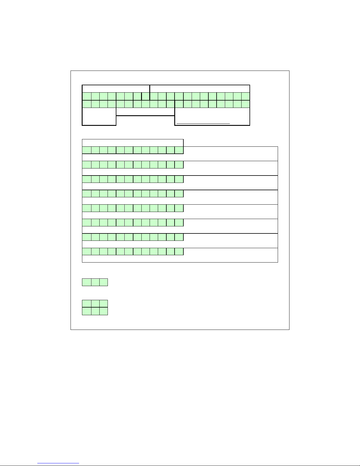
E09.012.246 Manual S-WG
60
10.3 Display during operation
During normal operation the text in the display shows the status of the water heater. In the following
graphs the several displays during normal operation are explained.
Display at WATER HEATER / HOT WATER DEMAND
Heat demand type:
Actual status:
W A T R H T R : S T A N D
- B Y
> > > : 1 2 3 . 4 ° C ( 1 2 3 . 4 ° C
)
cascade
communication indicator
temp. set point water temp.
measured temp.control.sens.
showing the measured temp.
Can be turned off by P5 BJ
Explanation "Actual status" screen
Actual status:
B o i l e r o f f
When water heater is switched off (only text in the display during this status).
N o d e m a n d
No heat demand signal coming from the room themostat and calorifier sensor (open).
S t a n d
- b y
Room themostat & calorifier sensor/themostat detect heat demand but set point is reached.
P r e
- p u r g e
The fan is purging before a burner start attempt.
P r e
- i g n i t i o n
Ignition starts before opening of the gas valve.
I g n i t i o n
The igniter is igniting.
P o s t - p u r g e
The fan is purging after burner is switched off.
B u r n i n g 1 0 0
%
When the burner is firing, also the actual rpm% is shown.
Explanation "Cascade communication indicator"
NO CASCADE COMMUNICATION
> > >
no.1
Always showing the fixed ">>>"
CORRECT CASCADE COMMUNICATION
> >
no.1
no.2
>
Showing alternating no.1 & no.2 with 1 second interval.
Page 60
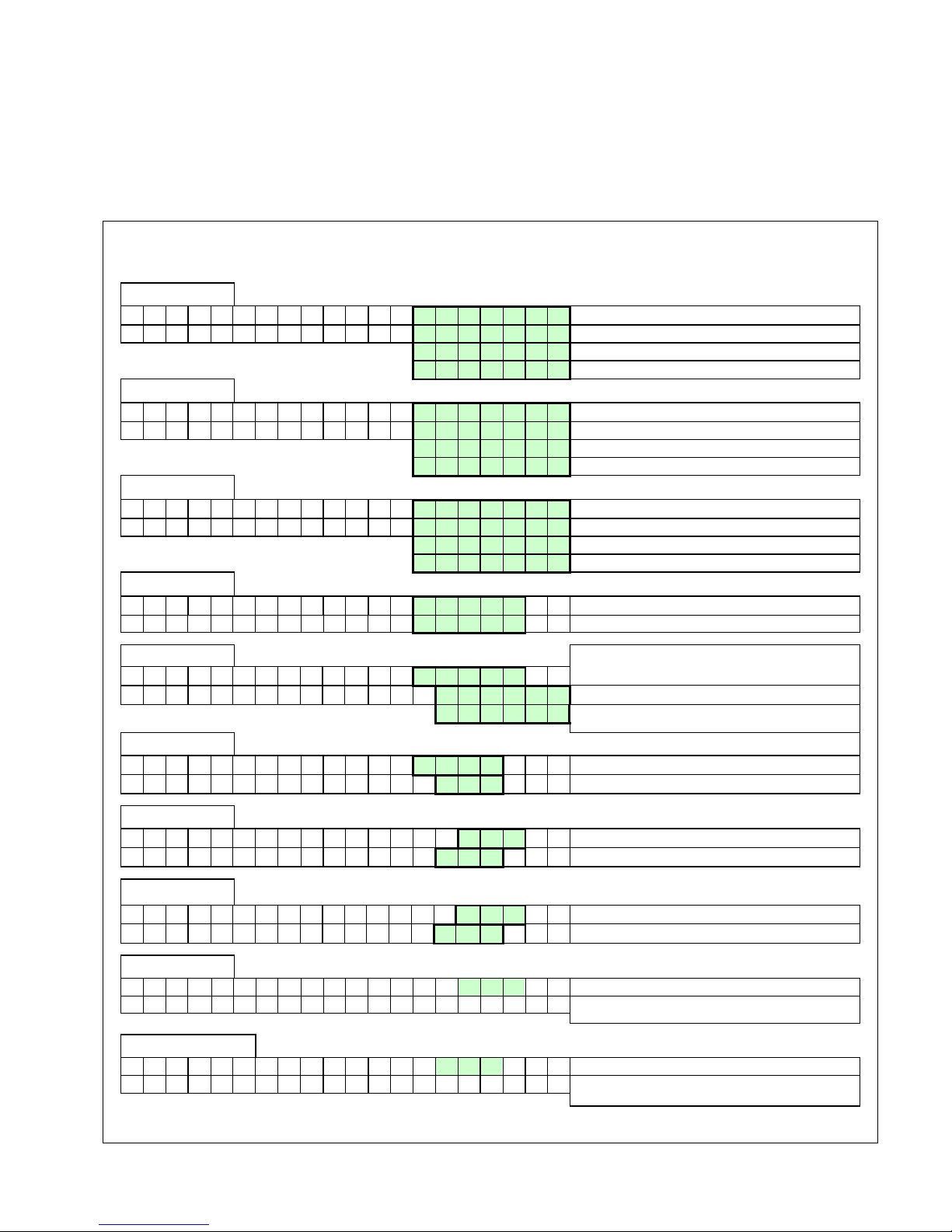
E09.012.246 Manual S-WG
61
10.4 Monitor screens
During normal operation and standby, the “◄” and “►” buttons can be used to show some water heater information, including measured temperatures, settings and data. In the following graphs is explained which values can
be shown in the display. When no button is activated for three minutes, the display will return to its status display.
Pressing [◄] or [►] while being at the "operating screen" toggles through the screens below.
When pressing [ON/OFF, RESET, ENTER] or [MENU] at any time the display returns to the base menu.
SCREEN: 1
T 1 F l o w 1 2 3 , 9 °
C
Measured value by the internal flow sensor.
T 2 R e t u r n 1 2 3 , 9 °
C
Measured value by the internal return sensor.
O p e n
Shown when controller doesn’t detect this sensor.
S h o r t e d
Shown when sensor wires or sensor itself is shorted.
SCREEN: 2
T 3 E x t e r n a l 1 2 3 , 9 °
C
Measured value by the external sensor.
T 4 C a l o r i f i 1 2 3 , 9 °
C
Measured value by the calorifier sensor.
O p e n
Shown when controller doesn’t detect this sensor.
S h o r t e d
Shown when sensor wires or sensor itself is shorted.
SCREEN: 3
T 5 O u t d o o r 1 2 3 , 9 °
C
Measured value by the outdoor sensor.
T 6 F l u e 1 2 3 , 9 °
C
Measured value by the flue gas sensor.
O p e n
Shown when controller doesn’t detect this sensor.
S h o r t e d
Shown when sensor wires or sensor itself is shorted.
SCREEN: 4
d T F l o w R e t u r n 1 2 3 , 9 °
C
Temp. difference between internal flow & return.
d T F l u e R e t u r n 1 2 3 , 9 °
C
Temp. difference between flue gas & internal return.
SCREEN: 5
Temp. difference between external & internal return
(ΔT LLH).
d T E x t R e t u r n 1 2 3 , 9 ° C S i g n a l P o w e
r
External supplied 0-10 Volt dc signal.
S e t p o
i
"Power" = power input control or "Setpoi" = set point
control.
SCREEN: 6
F a n s p e e d 9 9 9 9 r p
m
Actual fan speed in rpm.
F a n s p e e d 1 0 0
%
Actual fan speed % of maximum allowable fan speed.
SCREEN: 7
F l a m e s i g n a l 1 0 0 μ
A
Flame signal given in μA.
W a t e r P r e s s u r 1 , 0 b a
r
Shows water pressure when sensor is connected.
SCREEN: 8
P u m p 1 H e a t e r O f f
Pump 1 (HEATER PUMP) On or Off.
P u m p 1 S i g n a l 1 0 0 %
Modulating signal Pump 1 in (%).
SCREEN: 9
P u m p 2 C a l o r i O f f
Shows when the calorifier pump is "ON" or "OF".
3 - w a y V a l v e H e a t i n g
Signal to the 3-way valve: "HEATING" or "HOTWATER".
SCREEN: 10
P u m p 3 S y s t e m O f f
Shows when the system pump is "ON" or "OF".
h h : m m D D / M M / Y Y Y Y D a y
hh=hour; mm=minutes; DD=day; MM=month;
YYYY=yr; Day of the week
Page 61
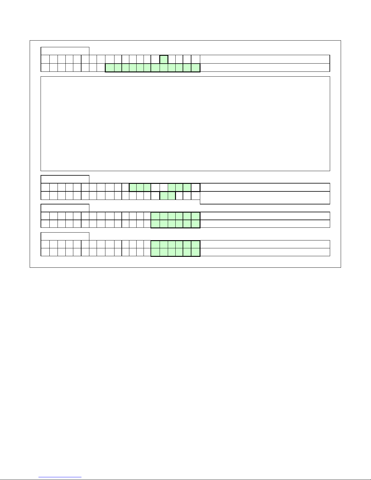
E09.012.246 Manual S-WG
62
SCREEN: 11
C a s c D e s i g n 0
0 = MASTER, 1 ..... 11 = SLAVES
C a s I n f 0 1 2 3 4 5 6 7 8 9 A
B
Displays number, priority and state of cascade water heaters.
DESCRIPTION "CASCINFO" Screen 11
Shows the number of water heaters connected with the cascade. The master/lead water heater is designated as
0. Slave/lag water heaters will be designated 1, 2, 3, 4, 5, 6, 7, 8, 9, A, B. When a “-“ is used instead of a number, then that water heater is either not connected, or in a lockout mode and not available for the cascade. When
an “x“ is used instead of a number, then that water heater is connected, but in lockout mode.
When the number is flashing, then that water heater is providing heat to the cascade. When the leading water
heater is changed according to the set priority change time, then that water heater’s address will be shown first in
the row of numbers.
Example 1: "3 4 5 - - - - - - 0 1 2"
There are six water heaters present and nr. 3 has priority.
Example 2: "3 4 x - - - - - - 0 1 2"
There are six water heaters present and nr. 3 has priority. Water heater 5 is present, but in a lock-out.
SCREEN: 12
C a s c P o w e r 9 9 9 % 9 9 9
%
% heat demand of total (cascade) power available (%).
D u a
l B u r n e r :
N o
One heat exchanger equipped with two burners: "Yes" or
"No".
SCREEN: 13
M a x T h e r m O p e n
Status of the maximum thermostat: "Open" or "Closed".
G e n B l o c k C l o s e
d
Status of the general blocking contact: "Open" or "Closed".
SCREEN: 14
S i p h o n p r e s s C l o s e
d
Status of the siphon pressure switch: "Open" or "Closed".
N R V C o n t a c t
O p e n
Status of the non-return valve contact: "Open" or "Closed".
Page 62
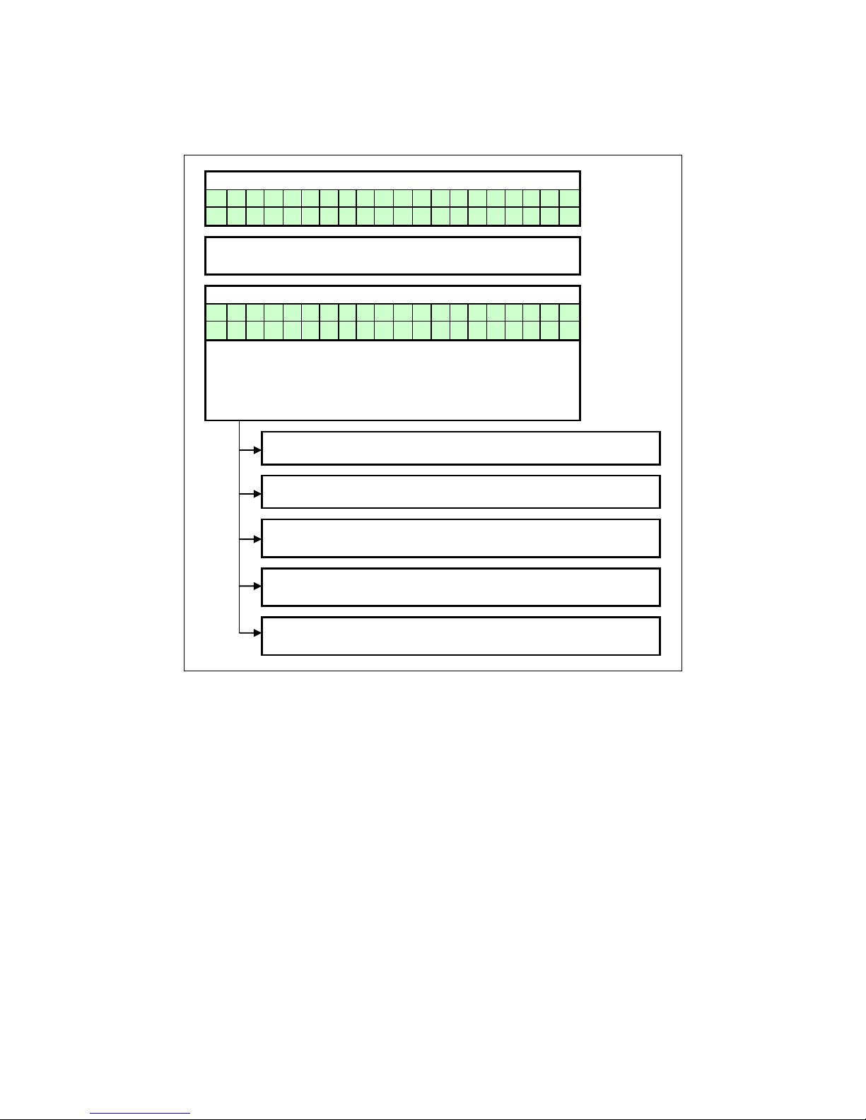
E09.012.246 Manual S-WG
63
10.5 Service function
The following graphs describe how to use the service function.
Operating screen:
W A T R H T R : S T A N D - B Y
> > > : 1 2 3 . 4 ° C ( 1 2 3 . 4 ° C
)
Press [SERVICE] and hold for 3 seconds.
The burner will start and show the display below.
Operating screen:
W A T R H T R : S e r v i c e 2 6
%
> > > 7 5 . 0 ° C ( 6 0 . 0 ° C
)
"WATRHTR": It is an appliance for DHW.
"Service": It is operating in service mode.
"26%": The burner is firing at 26%.
"75,0oC": Max. allowable water temp. during service.
"60,0oC": Actual measured water temp. (when P5BJ active).
Press [SERVICE] to exit. The unit will go to the operating screen.
Press 3 s. [ON/OFF] to exit. The unit will be switched off.
By using the [▲] & [▼] buttons the burner firing rate% can be
changed.
Press [MENU] to access the main menu.
Press [MENU] to return to the service menu.
Use [◄] & [►] buttons to browse through the monitor screens.
Press [MENU] to go to the operation menu of the service mode.
Press [SERVICE] to exit the service mode.
The unit will return to the standard operation display.
Page 63
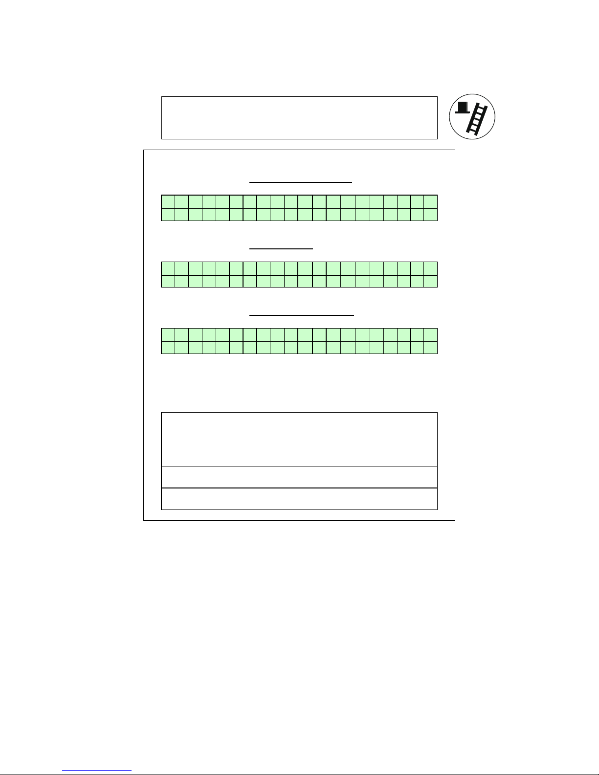
E09.012.246 Manual S-WG
64
10.6 Schornsteinfeger function
The purpose of this function is to have an easy interface for the
"Schornsteinfegers" in Germany, to be able to do their required
testing on the water heater. This is a simplified function similar to
the normal service function of the water heater.
When the "Schornsteinfeger" button is pressed for 3 seconds:
the heater will fire at minimum firing rate (%)
In this state the display shows:
F l u e s e r v i c e m o d e
P o w e r : M i n i m u m
When the button is pressed (briefly) again:
the heater will fire at 50% firing rate
In this state the display shows:
F l u e s e r v i c e m o d e
P o w e r : 5 0 %
When the button is pressed (briefly) again:
the heater will fire at maximum firing rate (%)
In this state the display shows:
F l u e s e r v i c e m o d e
P o w e r : M a x i m u m
When the button is pressed briefly again:
the heater will return to the normal operation mode.
The "Schornsteinfeger" function is switched off.
NOTES:
When the heater is burning during Schornsteinfeger function
(when top display line shows "Flue service mode") and no button
is pressed for 12 minutes, the water heater will return automatically to the normal operation mode. The "Schornsteinfeger" function will be switched off.
The "Schornsteinfeger function" can be activated for the user by
programming a parameter (P5 BK)
All regular temperature safety controls remain active and the water heater pump and system pump are running.
Page 64
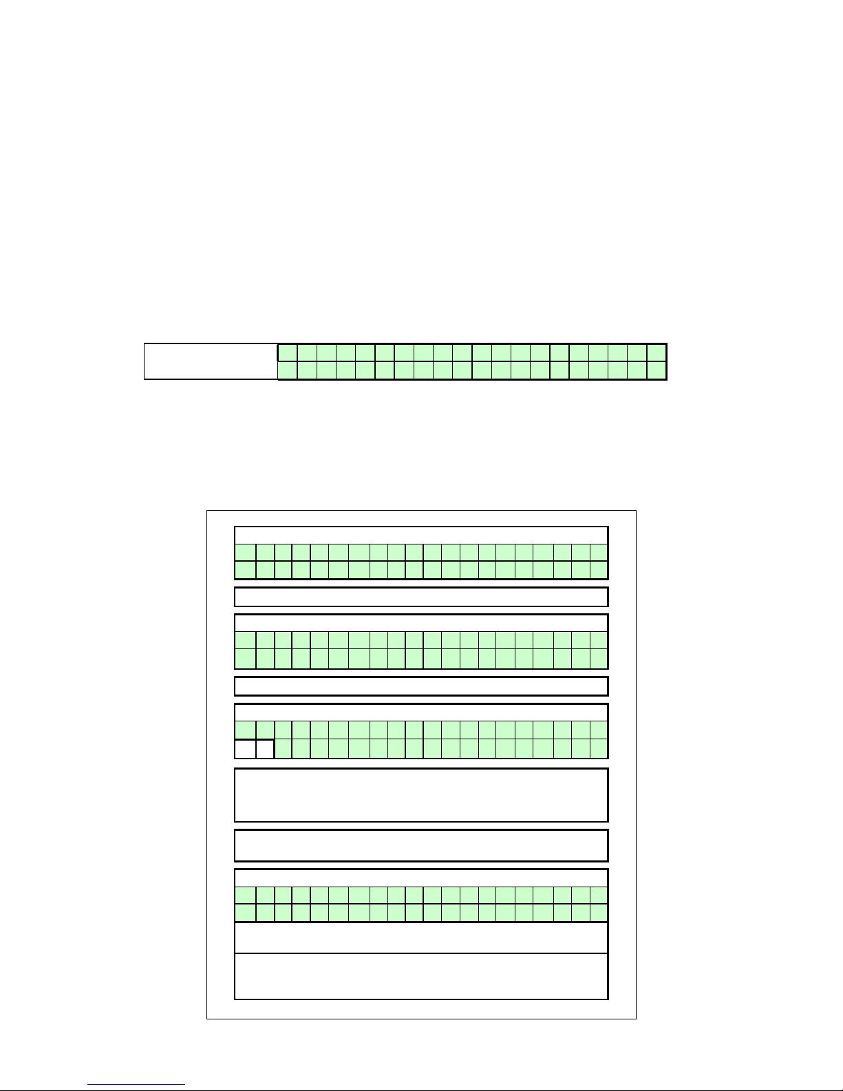
E09.012.246 Manual S-WG
65
10.7 Programming in standby mode
Standby
Use the standby mode for modifying water heater settings without interaction with the water heater control.
Changes are effectuated by leaving standby mode.
Properties of standby mode:
Keys are active and the menu is accessible.
Burner does NOT respond to an external heat demand.
All control functions are ON: pumps, fans and cascade are operational, recirculation and frost protection
are active.
How to programme the water heater:
Disconnect or shut down the room thermostat and/or other external controllers from the water heater.
The CH pump and fan will stop after a short time.
Switch the water heater in standby mode by pressing [ON/OFF] for three seconds.
The next display screen should appear:
Display message
W A T R H T R : b o i l e r o f f
> > > : 1 2 3 . 4 ° C ( 1 2 3 . 4 ° C
)
Program the water heater at the control panel (see the following sections).
Terminate programming mode by pressing [MENU], or [ENTER] and NO ◄ or YES ►.
Reactivate the water heater by pressing [ON/OFF] for three seconds again.
10.8 Setting the time & date
The following graphs describe how to program the time and date of the unit.
Operating screen:
W A T R H T R : S T A N D - B Y
> > > : 1 2 3 . 4 ° C ( 1 2 3 . 4 ° C
)
Press [MENU]
Main menu screen:
M a i n M e n u
C l o c k
The display shows "CLOCK" press [ENTER]
Setting Time and Date:
S e t t i m e / d a t e 0 8 : 3 3 3 0 / 0 3 / 2 0 1 0 T u e
The day is now blinking/selected and can be changed.
Use [▲] & [▼] to change the value.
Use [◄] & [►] to select another value.
Press [ENTER] for the confirmation screen after all changes
are done.
Confirmation screen:
A r e y o u s u r e
< C a n c e l ; > C o n f i r m
Press [◄] to cancel the changes made (display goes back to
operating screen).
Press [►] to confirm the changes made. The time and day will
start blinking for a few seconds. After this, the display returns to
its operating screen.
Page 65
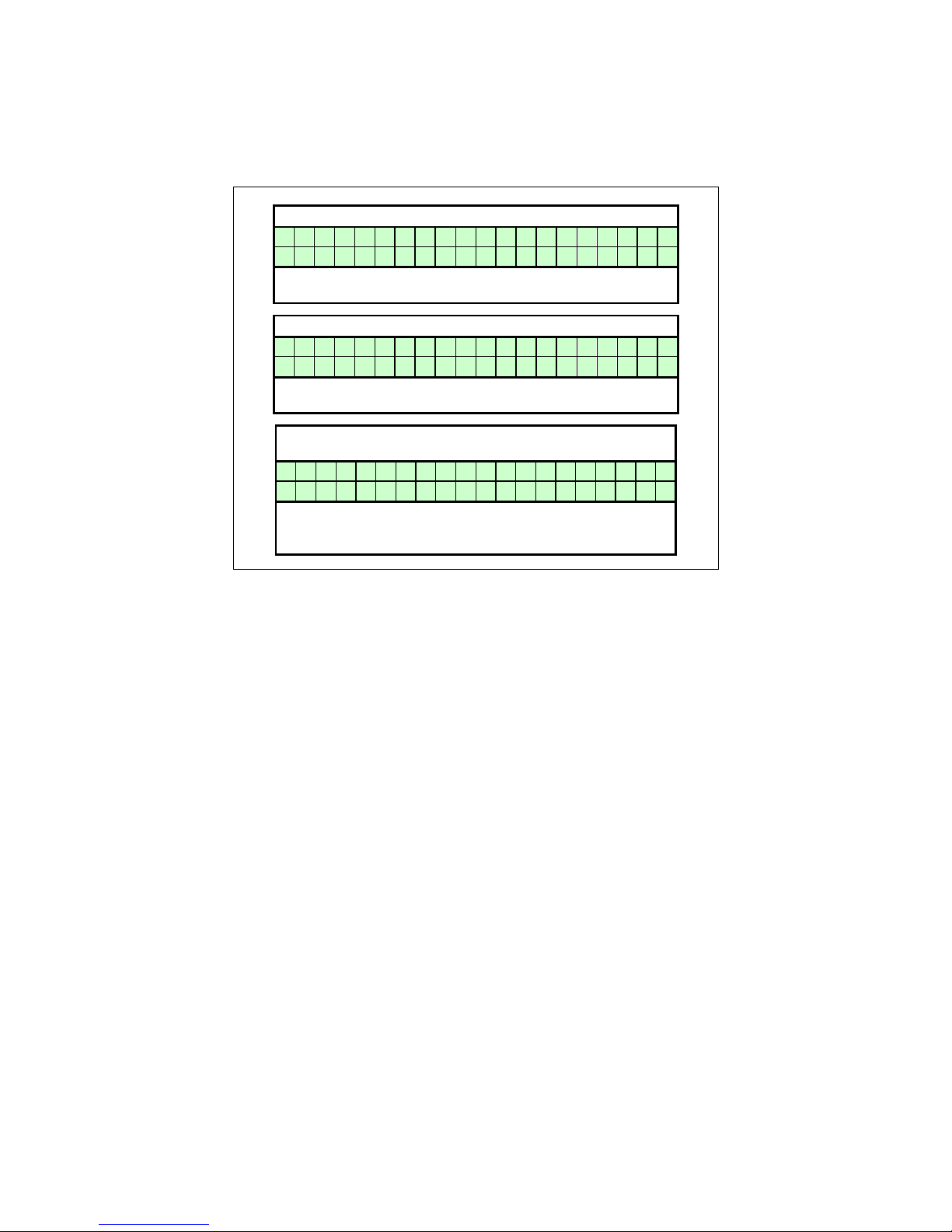
E09.012.246 Manual S-WG
66
10.9 Set points
The following graphs describe how to program the hot water set points.
Heating set point normal/day time: (parameter P4 AA = 1/2)
D H W s e t p o i n t
6 0 ° C
This is the water temperature set point that is active during
the programmed DHW periods (parameter P4 AA = 1/2)
DHW set point reduction: (parameter P4 AA = 1/2)
D H W R e d u c e
1 0 ° C
The reduction of the normal/day time set point. This reduction is used outside the programmed CH periods.
DHW setpoint reduction: (parameter P4 AA = 2 and
P5 DJ&DK =1)
H e a t i n g s e t p o i n t
7 5 ° C
This parameter is the local setpoint of the water heater and
is regulated on sensor S1 (parameter P4 AA = 2, P5 DJ = 1
and P5 DK =1 ).
Page 66
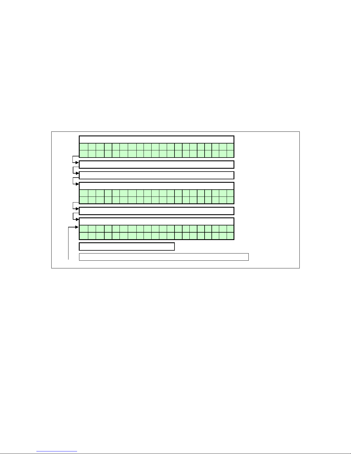
E09.012.246 Manual S-WG
67
10.10 Setting the timer programs
Two different programs can be set with the water heater, these are:
DHW program
Anti-legionnaires’ disease (pasteurisation) program
START PROGRAMMING
Three programmed periods each day can be set (period 1, 2 and 3). During this period the unit will use
the normal DHW set point. Outside the programmed period(s) the unit will use the reduced temperature
as set point. When no time is programmed for a period, it will not be used.
(Example no time programmed in period 3 on Monday > "Mon 3 --:-- ---:--").
Operating screen:
W A T R H T R : S T A N D - B Y > > > : 1 2 3 . 4 ° C ( 1 2 3 . 4 ° C
)
Press [MENU]
Select "Timer" using [◄] & [►] and press [ENTER]
Main menu screen:
M a i n M e n u
T i m e r
Press [ENTER]
Setting CH program times:
P r o g r a m C H M o n 1 0 6 : 0 0 - 2 3 : 0 0
Press [◄] for next SCREEN
> > > Continue on next page HOT WATER program < < <
Page 67
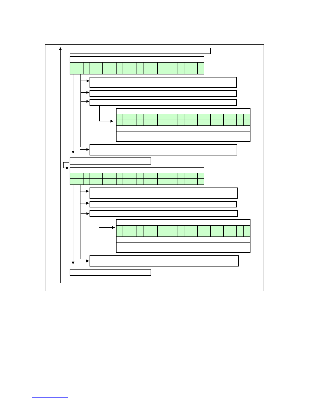
E09.012.246 Manual S-WG
68
HOT WATER PROGRAM
> > > From previous page < < <
Setting DHW program times:
P r o g r a m D H W
M o n 1 0 6 : 0 0 - 2 3 : 0 0
Press [►] to browse through the values that can be set at the bottom line.
The blinking value can be changed.
Press [▲] & [▼] to change the selected (blinking) value.
Press [ENTER] for confirmation screen when all settings are done.
Confirmation screen:
A r e y o u s u r e
< C a n c e l ; > C o n f i r m
Press [◄] to cancel the changes made (unit will reset).
Press [►] to confirm the changes. The last alternation will be blinking for a few seconds and return to base menu.
Press [MENU] to exit. The water heater will reset and go to the operating
screen.
Press [◄] for next SCREEN
Copy programmed day for DHW:
C o p y f r o m : D H W M o
n
C o p y t o : D H W T u
e
Press [►] to switch between "Copy from" and "Copy to". The blinking day is
selected and can be changed.
Press [▲] & [▼] to change the selected (blinking) value.
Press [ENTER] for confirmation screen when all settings are done.
Confirmation screen:
A r e y o u s u r e < C a n c e l ; > C o n f i r m Press [◄] to cancel the changes made (unit will reset).
Press [►] to confirm the changes. The two days will blink for a moment.
Press [MENU] to exit. The water heater will reset and go to the operating
screen.
Press [◄] for next SCREEN
> > > Continue on next page LEGIONELLA program < < <
Page 68
E09.012.246 Manual S-WG
69
ANTI LEGIONNAIRES’ DISEASE PROGRAM
See the following description. The standard factory setting for this function is “OFF”.
> > > From previous page with HOT WATER part < < <
Setting legionella program (day and time):
P r o g r a m L e g i o n e l l a
M o n 0 9 : 5 1
Press [►] to browse through the values that can be set at the
bottom line. The blinking value can be changed.
Press [▲] & [▼] to change the selected (blinking) value.
Press [ENTER] for confirmation screen when all settings are done.
Confirmation screen:
A r e y o u s u r e
< C a n c e l ; > C o n f i r m Press [◄] to cancel the changes made (unit will reset).
Press [►] to confirm the changes. The last alternation will be
blinking for a few seconds and return to base menu.
Press [MENU] to exit. The water heater will reset and go to the
operating screen.
Press [◄] for next SCREEN
Page 69
E09.012.246 Manual S-WG
70
10.11 Checking the operating history
The following graphs describe how to check the operating history of the water heater.
Operating screen:
W A T R H T R : S T A N D - B Y > > > : 1 2 3 . 4 ° C ( 1 2 3 . 4 ° C
)
Press [MENU]
Select "Operate" using [◄] & [►] and press [ENTER]
Main menu screen:
M a i n M e n u
O p e r a t e
Press [◄] & [►] to browse through the 5 screens.
Press [MENU] or [ENTER] to exit. The unit will return to the
operating screen.
SCREEN: 1
O p e r a t i n g h i s t o r y
P o w e r O n h r s 1 3 1 4 0 0
Top line: Shows the operating history menu is activated.
Bottom line: Total hours the water heater is connected to power
supply and switched on.
SCREEN: 2
h r s C h T o t 1 0 0 0 0 0 0 h r s D h w T o t 1 0 0 0 0 0
0
Top line: Total burning hours for heating.
Bottom line: Total burning hours for domestic hot water.
SCREEN: 3
h r s C h < 5 0 % 1 0 0 0 0 0 0 h r s C h = > 5 0 % 1 0 0 0 0 0
0
Top line: Burning hours for heating while the burner was firing
less than 50%.
Bottom line: Burning hours for heating while the burner was
firing equal or higher than 50%.
SCREEN: 4
h r s D h w < 5 0 % : 1 0 0 0 0 0 0 h r s D h w = > 5 0 % : 1 0 0 0 0 0
0
Top line: Burning hours for hot water while the burner was firing
less than 50%.
Bottom line: Burning hours for hot water while the burner was
firing equal or higher than 50%.
SCREEN: 5
T i a 1 0 0 0 0 0 F i a 1 0 0 0 0 0 S s l 1 0 0 0 0 0 S s t 1 0 0 0 0 6
Top line: Shows Total Ignition Attempts (Tia) & Failed Ignition
Attempts (Fia)
Bottom line: Shows Soft Starts last (Ssl) &
Soft Starts Total (Sst)
Page 70
E09.012.246 Manual S-WG
71
10.12 Checking the fault history
The following graphs describe how to check the fault history of the water heater.
Operating screen:
W A T R H T R : S T A N D - B Y
> > > : 1 2 3 . 4 ° C ( 1 2 3 . 4 ° C
) Press [MENU]
Select "Faulthist" using [◄] & [►] and press [ENTER]
F a u l t h i s t N o . 0
1
2 1 / 0 4 / 2 0 1 0 W e d 2 2 : 2 3
A
▲ blinking ▼
S i p h o n S w i t c h
S v 9 9 9 / C U M 9 9 9 / R 9 9 9 9 ,
5 Press [◄] & [►] to browse through the last 10 faults.
Press [MENU] or [ENTER] to exit. The unit will return to
The fault menu shows the last 10 faults. For each fault the
display blinks between the two screens shown above. The
top line of the top screen shows the fault number and the
bottom line of the top screen shows the date, day and time
the fault occurred.
On the top line of the bottom screen the fault type is displayed. The bottom line shows the following:
SV: The total amount of this fault that has occurred after
the last time that the service history was erased (after service was done).
CUM: The total amount of this fault. The total amount cannot be erased after service, this shows the fault history of
the water heater (electronics) since the start of operation.
R: Shows the elapsed time in hrs between the moment the
fault occurred and the moment it was reset.
Page 71
E09.012.246 Manual S-WG
72
10.13 Setting the maintenance specifications
MAINTENANCE SETTINGS
The unit can be programmed in such a way that an automatic maintenance message is displayed.
There are three options that can be selected. A maintenance message appears after:
* A programmed date is reached.
* An amount of burning hours is reached.
* An amount of ignition cycles is reached.
A single option can be activated or all three options.
Operating screen:
W A T R H T R : S T A N D - B Y
> > > : 1 2 3 . 4 ° C ( 1 2 3 . 4 ° C
)
Press [MENU]
Select "Maintenan" using [◄] & [►] and press [ENTER]
Operating screen:
M a i n t e n R e s e t
Press [▲] to reset the:
Counter for the total amount of burning hours.
Counter for the total amount of ignition cycles.
(The text will blink once briefly after resetting).
Operating screen:
M a i n t e n M o d e
Blinking second line.
What is blinking at the second line (before a selection is made) is the
active maintenance option.
Press [▲] or [▼] to change the selected
blinking option.
Screen: Selecting of all maintenance options.
M a i n t e n M o d e
A l l
Press [►] to set:
The option that is blinking can be changed using by [▲] & [▼]
* Date for the Maintenance message.
* Total amount of burning hours for the Maintenance message.
* Total amount of ignition cycles for the Maintenance message.
After selecting one of these values the water heater returns to the
maintenance operating screen.
Press [ENTER] to confirm the changes.
Confirmation screen:
A r e y o u s u r e
< C a n c e l ; > C o n f i r m
Press [◄] to cancel the changes or [►] to confirm the
changes. Hereafter the water heater returns to the
operating screen.
Go to next page
Page 72
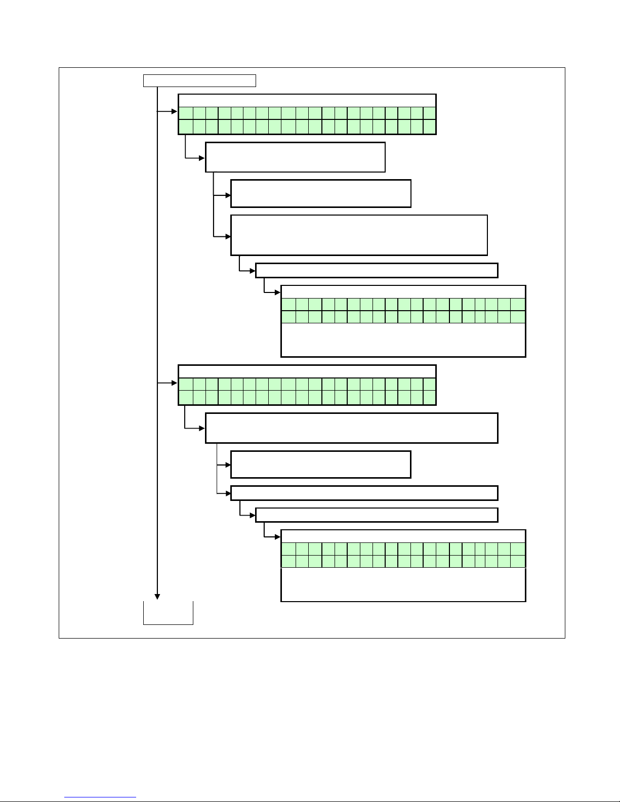
E09.012.246 Manual S-WG
73
From previous page
Screen: Selecting message at certain date.
M a i n t e n M o d e
D a t e
Press [►] to set:
The date for the maintenance message.
Press [◄] to:
Return to maintenance mode selection.
Press [►] to browse through the values that can be set
at the bottom line.
The blinking value can be changed with [▲] & [▼]
Press [ENTER] to confirm the changes.
Confirmation screen:
A r e y o u s u r e < C a n c e l ; > C o n f i r
m
Press [◄] to cancel the changes or [►] to confirm the
changes. Hereafter the water heater returns to the operating screen.
Screen: Message after total amount of ignition cycles.
M a i n t e n M o d e
I g n i t i o n c y c l e s
Press [►] to set:
The total amount of ignition cycles for the Maintenance message.
Press [◄] to:
Return to maintenance mode selection.
The blinking value can be changed with [▲] & [▼]
Press [ENTER] to confirm the changes.
Confirmation screen:
A r e y o u s u r e < C a n c e l ; > C o n f i r
m
Press [◄] to cancel the changes or [►] to confirm the
changes. Hereafter the water heater returns to the operating screen.
Go to
next page
Page 73
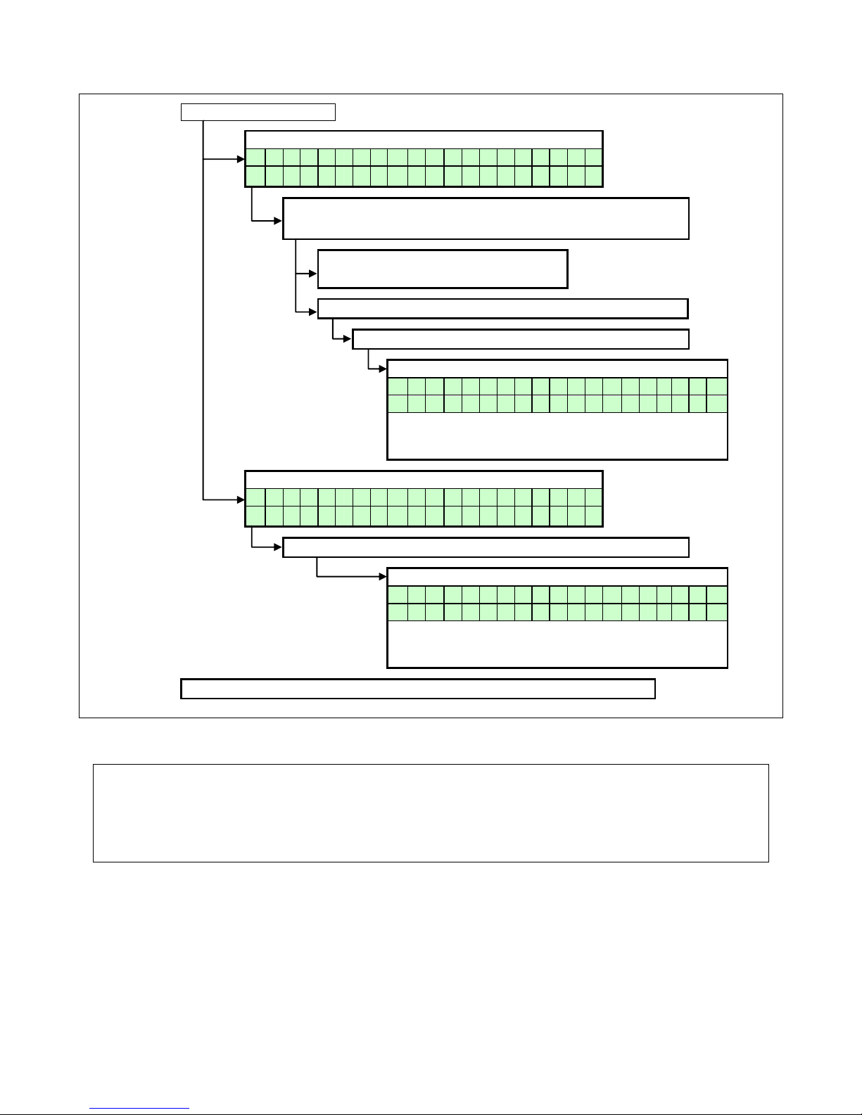
E09.012.246 Manual S-WG
74
From previous page
Screen: Message after total amount of burning hours.
M a i n t e n M o d e
B u r n i n g h o u r s
Press [►] to set:
The total amount of burning hours for the maintenance message.
Press [◄] to:
Return to maintenance mode selection.
The blinking value can be changed with [▲] & [▼]
Press [ENTER] to confirm the changes.
Confirmation screen:
A r e y o u s u r e
< C a n c e l ; > C o n f i r m
Press [◄] to cancel the changes or [►] to confirm the
changes. Hereafter the water heater returns to the operating screen.
Screen: No maintenance message will be displayed.
M a i n t e n M o d e
M a i n t e n O f f
Press [ENTER] to confirm the changes.
Confirmation screen:
A r e y o u s u r e < C a n c e l ; > C o n f i r
m
Press [◄] to cancel the changes or [►] to confirm the
changes. Hereafter the water heater returns to the operating screen.
Note: The [MENU] button will return the display to the operating screen.
BE AWARE: This function is standard turned OFF. We offer this programmable function to the installer to use as
a reminder. Because it concerns a free programmable function the use of it cannot be used as an argument in
warranty cases.
Our units must be maintained every twelve months whatever the settings/working of this function.
It is and remains the responsibly of the end user to have the unit maintained every twelve months.
Page 74
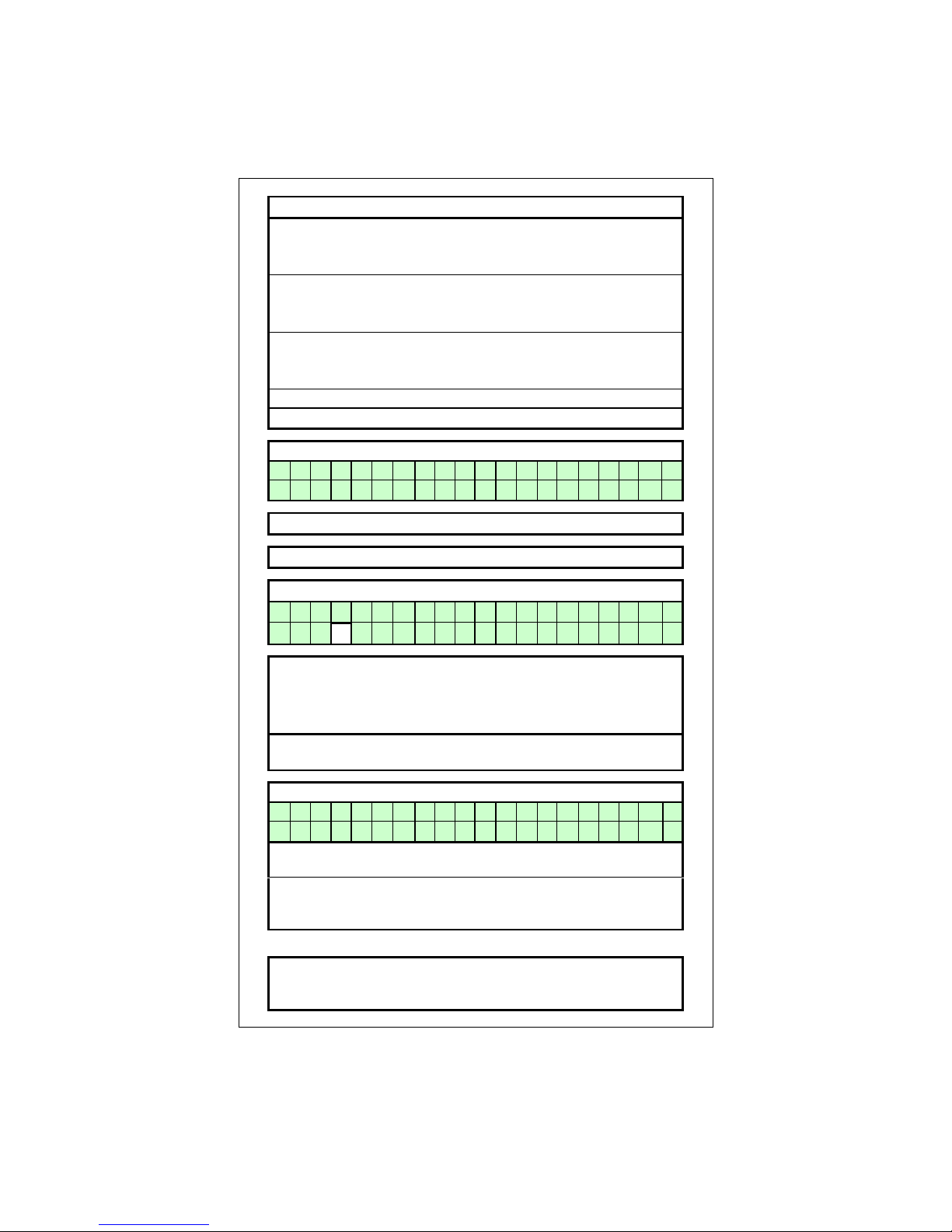
E09.012.246 Manual S-WG
75
10.14 Setting the user lock
The following graphs describe how to activate the user lock of the display. The standard factory setting for this
function is “OFF”.
The "USER LOCK" menu.
In this menu the water heater can be locked for (end-)users.
0 = UNLOCKED
1 = LOCKED
When the water heater is unlocked, the user can enter the
MENU by pressing the menu button and all screens
will show up.
When the water heater is locked, the user has to push the:
[MENU] button together with the [▼] button for 5 s.
to access all menu screens.
This function is to prevent accidental changes!
NOTICE: The PARAMETER screen always accessible.
Operating screen:
H E A T I N G : S T A N D
- B Y
> > > : 1 2 3 . 4 ° C ( 1 2 3 . 4 ° C
)
Press [MENU]
Select "User lock" using [◄] & [►] and press [ENTER]
User lock screen:
S e t U s e r l o c k = 0 0
The "0" is now blinking/selected and can be changed.
Use [▲] & [▼] to change the value.
0 = User lock function OFF
1 = User lock function ON
Press [ENTER] for the confirmation screen after the selection
has been made.
Confirmation screen:
A r e y o u s u r e
< C a n c e l ; > C o n f i r m
Press [◄] to cancel the changes (the unit will reset and the
display returns to the operating screen).
Press [►] to confirm the changes. The changed value will be
blinking for a few seconds. After this, the display returns to the
operating screen.
NOTICE:
Using the [MENU] button during the User lock display, will
reset the water heater and the water heater will return to the
operating screen. Changes will be neglected in this case.
Page 75
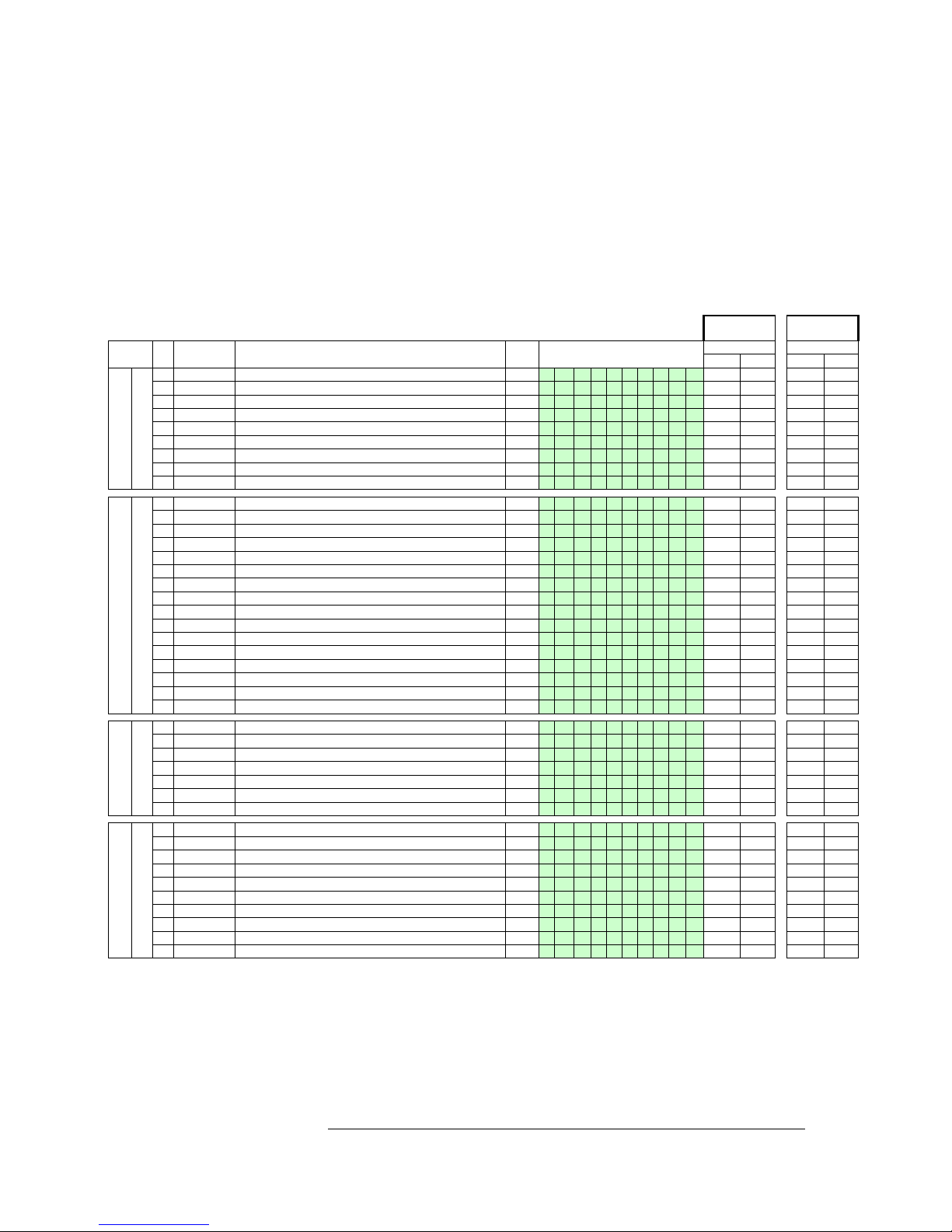
E09.012.246 Manual S-WG
76
10.15 Setting the parameters with the display menu
The functions of the controller are embedded in de electronics. The values and settings that are being used for
these controlling functions can be changed by programming these values. This can be done by a skilled and
trained service engineer with the help of a computer, the correct software and an interface cable. The values and
settings that are used for these controlling functions are called parameters. A selection of these parameters can
be programmed on the unit itself, without the use of a computer. These settings can easily be done at the control
panel of the water heater.
The following table gives a list of these parameters that can be programmed by the display. All parameters that
are shown in the display, can be changed. NOTICE: Only the password for level 1 is issued in this manual.
When other “more advanced” parameters needs to be programmed, it can only be done by a skilled and trained
service engineer, who has access to level 2.
PASSWORD:
1342
PASSWORD:
MENU
SOFTW.
PARAM
DESCRIPTION
UNITS
TEXT DISPLAY
LEVEL 1
LEVEL 2
Display
Modify
Display
Modify
HEATING
A
1
P5BE
Step modulation (1=on 0=off)
-
S t e p m o d u
l
yes
no
yes
yes 2 P5AO
Blocking offset flow temperature control
°C
H E s O f f 1
3
yes
yes
yes
yes 3 P5AP
Proportional range temperature control
°C
H E s P r b 1
3
yes
no
yes
yes 4 P5AL
Hysteresis CH Flow temperature control
°C
H E s c D i f 1
3
yes
yes
yes
yes 5 P2IC
Integration time temperature control
s
H E s I n t 1
3
yes
no
yes
yes 6 P2MI
Blocking offset System CH temperature control
°C
H E c O f f
3
yes
yes
yes
yes 7 P2MJ
Proportional range System CH temperature control
°C
H E c P r b
3
yes
no
yes
yes 8 P2MK
Integration time CH temperature control
s
H E c I n t
3
yes
no
yes
yes 9 P5AB
Timer Contact (1=on)
-
T i m e r C o n t
yes
yes
yes
yes
DHW
B
1
P4AB
DHW Pump Config 0=Pump 1=TWV
-
D H i p m p / t w
v
yes
yes yes
yes 2 P5CB
Flow temperature DHW tank low
°C
D H i f l o w L
O
yes
yes
yes
yes 3 P5CK
Flow temperature DHW tank hi
°C
D H i f l o w H
I
yes
yes
yes
yes 4 P5CL
Low Flow temperature time DHW
min
D H i L O t i m
e
yes
yes
yes
yes 5 P5CD
Legionella temperature
°C
L e g i o t e m
p
yes
no
yes
yes 6 P5CI
Legionella hyst DHW tank temperature
°C
L e g i o h y s
t
yes
no
yes
yes 7 P5CJ
Legionella hold time (0=off)
min
L e g i o h o l
d
yes
no
yes
yes 8 P2KI
CH interrupt by Legionella (0=yes)(1=no)
-
L e g i o i n t
r
yes
no
yes
yes 9 P2LC
Regulation temperature offset DHWd
°C
D H d s c O f f 2
yes
yes
yes
yes A P2LE
Proportional range DHWd modulation
°C
D H d s c P r b 2
3
yes
no
yes
yes B P2LD
Regulation temperature hysteresis DHWd
°C
D H d s c D i f 2
yes
yes
yes
yes C P2LF
integration time DHWd modulation
s
D H d s c I n t 2
3
yes
no
yes
yes D P2ML
Sys temp blocking offset DHW tank
°C
D H d s c O f f 3
yes
yes
yes
yes E P2MM
Sys temp blocking hysteresis DHW tank
°C
D H d s c D i f 3
yes
yes
yes
yes F P5CA
Hysteresis DHW tank temperature
°C
D H i s c D i f 4
yes
yes
yes
yes G P2KH
Gradient heat demand detect DHW tank temperature
°C
D H i d e t g r a
d
yes
yes
yes
yes
CASCADE
C
1
P2MA
Max number extra water heaters
-
M a x C a s c U n
t
yes
no yes
yes 2 P5DA
Bus address water heater
-
B u s a d r e s
s
yes
no
yes
yes 3 P5DC
Dhw on entire cascade(0) only master(1)
-
D H i c a s / m a
s
yes
no
yes
yes 4 P5DE
Extra Water heater output enable(1)
-
E x t r a u n i
t
yes
yes
yes
yes 5 P5DF
Cascade detection (0=standalone 1=Leader)
-
C a s S i / M a
yes
no
yes
yes 6 P5BL
Power off total cascade (1)
-
P w r O f f T o C
a
yes
no
yes
yes 7 P5DB
Number of water heaters with common flue 0=None
-
C o m F l u N u m
yes
no
yes
yes
GENERAL
D
1
P5BB
Analogue input Config (0=off 1=temp 2=power)
-
A n I n p C o
n
yes
yes yes
yes 2 P5AI
Minimum Temperature 0-10V input
°C
0 - 1 0 M i n T m
p
yes
yes
yes
yes 3 P5BI
Altitude (in amounts of 100 ft.)
ft*100
A l t * 1 0 0 f
t
yes
yes
yes
yes 4 P2LK
Max cooling time
min
M a x C o o l T i
m
yes
yes
yes
yes 5 P5BJ
Temperature display 1=on
-
T e m p O n D i s
p
yes
yes
yes
yes 6 P4AA
DHW 0=off 1=Indirect 2=Direct
-
D H W 1 = i 2 =
d
yes
no
yes
yes
7
P4AD
pressure 0=off 1=sensor and 2=switch
-
c o n f i g
yes
no
yes
yes 8 P4BD
Gas type values 0-2
-
g a s t y p e
yes
no
yes
yes 9 P4BE
Soft start type values 0-2
-
c o n f i g
yes
no
yes
yes A P5BN
Pump modes 0-4
-
c o n f i g
yes
no
yes
yes
In the parameter table shown above one can see all the parameters that can be set on the unit without the use of
a laptop/computer.
In the following chapter “Controlling options and settings” the controlling options for hot water and cascading are
explained. In the explanation of these options there is a reference of all relevant parameters which are shown in
the table above and can be set on the unit.
IMPORTANT:
Do not change the parameters P2LC, P2LD, P2ML, P2MM and P5BI; they are present in the controller for different purposes than DHW control. Changing these parameters may affect water heater operation negatively!
Page 76
E09.012.246 Manual S-WG
77
The following graphs describe how to program the parameters by using the display:
Operating screen:
W A T R H T R : S T A N D - B Y
> > > : 1 2 3 . 4 ° C ( 1 2 3 . 4 ° C
) Press [MENU]
Select "Parameter" using [◄] & [►] and press [ENTER]
Parameter menu:
I n s t a l l e r c o d e
0 0 0 0
Enter the 4-digit code with the [◄] & [►] and the
[▲] & [▼] buttons and select [ENTER]
The code will blink a few seconds and when entered
correctly, the following parameters will be displayed.
NOTICE: These codes are user based and give access
to a selected amount of parameters, which
can be changed (Installer level 1/2).
Menu A: Heating
A 1 S t e p m o d u l
1
Function to activate the step modulation:
0 = Off
1 = On
Menu A: Heating
A 2 H E s o f f 1 3 4 ° C
CH supply temperature setting. This parameter
is the offset of the programmed CH temperature.
Menu A: Heating
A 3 H E s P r b 1 3
2 5 ° C
Select the CH supply temperature control. This parameter
is the proportional range of the selected CH supply temperature.
Menu A: Heating
A 4 H E s c D i f 1 3
1 0 ° C
Select the CH supply temperature control. This parameter
is the hysteresis of the selected CH supply temperature.
Menu A: Heating
A 5 H E s l n t 1 3
6 0 S e c
Select the CH supply temperature control. This parameter
is the integration time of the selected CH supply temperature.
The screen texts on these pages are
standard part of the software and
apply to CH systems (boilers) and/or
DHW devices (water heaters).
Page 77
E09.012.246 Manual S-WG
78
Menu A: Heating
A 6 H E c O f f 3 4 ° C
Select the cascaded boilers supply temperature control.
This parameter is the offset of the selected CH
supply temperature of EACH boiler of the total cascade.
Menu A: Heating
A 7 H E c P r b 3 2 5 ° C
Select the cascaded boilers supply temperature control.
This parameter is the proportional range of the selected
CH supply temperature of EACH boiler of the total
cascade and of the external (cascade) sensor.
Menu A: Heating
A 8 H E c l n t 3
8 0 S e c
Select the cascaded boilers supply temperature control.
This parameter is the integration time of the selected
CH supply temperature of EACH boiler of the total
cascade and of the external (cascade) sensor.
Menu A: Heating
A 9 T i m e r C o n t 0
Function to activate "external time controller":
0 = Off
1 = On
Connect to 13-14. Contact closed = daytime setting,
Contact open = night-time setting.
Menu B: Hot water
B 1 D H i p m p / t w v 1
Hot water function of the boiler by:
0 = pump
1 = 3-way valve
Menu B: Hot water
B 2 D H i f l o w L O 2 5 ° C
Hot water function of the boiler. This parameter is the
CH supply temperature LOW level with an indirect
hot water demand.
Menu B: Hot water
B 3 D H i f l o w H I 8 5 ° C
Hot water function of the boiler. This parameter is the
CH supply temperature HIGH level with an indirect
hot water demand.
The screen texts on these pages are
standard part of the software and
apply to CH systems (boilers) and/or
DHW devices (water heaters).
Page 78
E09.012.246 Manual S-WG
79
Menu B: Hot water
B 4 D H i L O t i m e
1 M i n
Hot water function of the boiler. This parameter is the
selectable time period after which the boiler switches
from LOW to HIGH set point with an indirect hot water
demand.
Menu B: Hot water
B 5 L e g i o t e m p 8 5 ° C
Pasteurisation function of the boiler. This parameter is the
selected hot water temperature during the pasteurisation
function of the boiler.
Menu B: Hot water
B 6 L e g i o h y s t 2 ° C
Pasteurisation function of the boiler. This parameter is the
selected hysteresis during the pasteurisation
function of the boiler.
Menu B: Hot water
B 7 L e g i o h o l d
2 M i n
Pasteurisation function of the boiler. This parameter is the
selected time period for the pasteurisation
function of the boiler.
Menu B: Hot water
B 8 L e g i o i n t r
0
Pasteurisation function of the boiler. This parameter
controls if the CH demand can be interrupted by the
pasteurisation function of the boiler.
0 = Yes
1 = No
Menu B: Hot water
B 9 D H d s c O f f 2 4 ° C
Function for the direct hot water boiler.
This parameter is de off set of the selected HW
temperature of the boiler.
Menu B: Hot water
B A D H d s c P r b 2 3
2 0 ° C
Function for the direct hot water boiler.
This parameter is the proportional range of the selected
HW temperature of the boiler.
The screen texts on these pages are
standard part of the software and
apply to CH systems (boilers) and/or
DHW devices (water heaters).
Page 79
E09.012.246 Manual S-WG
80
Menu B: Hot water
B B D H d s c D i f 2 1 0 ° C
Function for the direct hot water boiler.
This parameter is the hysteresis of the selected
HW temperature of the boiler.
Menu B: Hot water
B C D H d s c l n t 2 3 2 0 0 S e c
Function for the direct hot water boiler.
This parameter is the integration time of the selected
HW temperature of the boiler.
Menu B: Hot water
B D D H d s c O f f 3 4 ° C
Function for the cascaded direct hot water boilers.
This parameter is the offset of the selected
HW temperature of the cascaded boilers.
Menu B: Hot water
B E D H d s c D i f 3 8 ° C
Function for the cascaded direct hot water boilers.
This parameter is the hysteresis of the selected
HW temperature of the cascaded boilers.
Menu B: Hot water
B F D H i s c D i f 4 5 ° C
Function for the indirect hot water supply of the
boiler (tank).
This parameter is the hysteresis of the selected
HW temperature of the calorifier/tank.
Menu B: Hot water
B G D H i d e t g r a d 3 ° C
Function for the indirect hot water supply of the
boiler (tank).
This parameter detects an (an accelerated) hot water
demand, when a larger (water) amount is being used.
Menu C: Cascade
C 1 M a x C a s c U n t 1 1
Function for the cascading of the boiler(s).
This parameter sets the total amount of cascaded boilers.
(Max. 12 boilers).
The screen texts on these pages are
standard part of the software and
apply to CH systems (boilers) and/or
DHW devices (water heaters).
Page 80
E09.012.246 Manual S-WG
81
Menu C: Cascade
C 2 B u s a d r e s s 0
Function for the cascading of the boiler(s).
This parameter determines the address of the boiler
for the total cascading control.
Master = 0, Slave 1 = 1 etc.
Menu C: Cascade
C 3 D H i c a s / m a s 0
Function for the cascading of the boiler(s).
This parameter determines if only the Master boiler or all
boilers of the cascade are used for indirect hot water.
0 = All
1 = Master
Menu C: Cascade
C 4 E x t r a u n i t 0
Function for the cascading of the boiler(s).
This parameter is activated when an external (extra) boiler
is connected to the Master boiler. Connect to the Master
connections 21-22.
Menu C: Cascade
C 5 C a s S i / M a 0
Function for the cascading of the boiler(s).
This parameter sets the function of the boiler at a cascade
alignment
0 = Single / Slave unit
1 = Master unit
Menu C: Cascade
C 6 P w r O f f T o C a
0
Function for the cascading of the boiler(s).
This parameter determines the function of the Slave boilers
when the Master boiler is switched off.
0 = Slave boiler(s) continue operation
1 = Slave boiler(s) switch off
Menu C: Cascade
C 7 C o m F l u N u m 0
Function for the cascading of the boiler(s).
This parameter determines the number of cascaded boilers,
that are implemented with a common flue system.
The screen texts on these pages are
standard part of the software and
apply to CH systems (boilers) and/or
DHW devices (water heaters).
Page 81
E09.012.246 Manual S-WG
82
Menu D: General
D 1 0 - 1 0 V c o n t r 0
Function for the external control of the boiler by using
a 0-10 Volt signal (Connections 15-16).
0 = No external control
1 = Control based on temperature setting
2 = Control based on power setting
Menu D: General
D 2 0 - 1 0 M i n T m p 2 0 ° C
Function for the external control of the boiler by using
a 0-10 Volt signal (Connections 15-16).
Control based on temperature (setting 1).
The minimum (desired) CH water temperature when
supplying a 1 Volt signal.
Menu D: General
D 3 A l t * 1 0 0 f 0
Function for setting the location height (above sea level)
of the boiler.
NOTICE: dimensions in English feet. One unit = 100 ft.
Use this function only in consultation with the supplier/manufacturer.
Menu D: General
D 4 M a x C o o l T i m
2 M i n
Function for setting the maximum overrun time of the fan
(Maximum 10 minutes).
0 = Switch off
Menu D: General
D 5 T e m p O n D i s p
1
Function to show the (measured) temperature of the boiler at
the display.
Menu D: General
D 6 D H W 1 = i 2 = d 1
Function to set up the CH and HW boiler options.
0 = CH only (direct)
1 = CH/HW function (indirect)
2 = HW only (direct)
The screen texts on these
pages are standard part of the
software and apply to CH systems (boilers) and/or DHW
devices (water heaters).
Page 82
E09.012.246 Manual S-WG
83
Menu D: General
D 7
c o n f i g
Function for the setting of the water pressure.
Up to 4 bar a sensor is used, up to 6 bar a switch.
0 = off
1 = sensor
2 = switch
Menu D: General
D 8
g a s t y p e
Function to select the gas type
0 = standard
1 = G31*
2 = B/P G30*/G31*
* (cf. EN437)
Menu D: General
D 9
c o n f i g
Function for setting the 'soft start' option
0 = normal start-up
1 = reduced fan ramp-up speed (I)
2 = reduced fan ramp-up speed (II)
Menu D: General
D A
c o n f i g
Function: Pump mode
0 = normal
1 = relay 1, connector 19 and 20 (lock-out)
2 = relay 2, connector 21 and 22 (burner burning)
3 = relay 3, connector 23 and 24 (heat demand)
4 = relay CN10, connector 9 and 18
The screen texts on these
pages are standard part of
the software and apply to CH
systems (boilers) and/or DHW
devices (water heaters).
Page 83
E09.012.246 Manual S-WG
84
10.16 Fault codes display
The following graphs describe the lock out codes of the water heater. A lock out code can only be removed by a
manual reset of the water heater. NOTICE: Before resetting the water heater always check the water heater,
DHW system and all components corresponding to the related lock out description. Never just reset the water
heater, before analysing the possible cause of failure.
10.16.1 LOCK-OUT CODES
Having a lockout means that the water heater needs a manual reset to start operating again.
When the water heater is in lockout the backlight of the display is blinking on and off.
Explanation >
9 9 9 , 5 : h r s
= time elapsed after fault & message.
Explanation >
P u m p 1 o
n
= status of the pump during fault.
Display message
F0
F l o w s e n s o r e r r o r p u m p o n 9 9 9 , 5 h r
s
Reason
Flow sensor not detected by the water heater caused by faulty connection/sensor.
Display message
F1
F l o w h i g h T e m p
p u m p o n 9 9 9 , 5 h r
s
Reason
Flow temperature exceeds the limit which has been set in the parameters.
Display message
F1
R e t u r n h i g h T e m p
p u m p o n 9 9 9 , 5 h r
s
Reason
The maximum return temperature as set in the parameters is exceeded.
Display message
F2
L a c k o f w a t e r p u m p o n
9 9 9 , 5 h r s
Reason
The general required gradient water lack has failed.
Display message
F3
R e t u r n s e n s o r e r r o r
p u m p o n 9 9 9 , 5 h r
s
Reason
Return sensor not detected by the water heater caused by faulty connection / sensor.
Display message
F5
N o n R e t u r n V a l v e
p u m p o n
9 9 9 , 5 h r s
Reason
Contact signal of the non-return valve failed.
Display message
F6
F l u e s e n s o r e r r o r p u m p o n 9 9 9 , 5 h r
s
Reason
Flue gas sensor not detected by the water heater caused by faulty connection / sensor.
Display message
F7
F l u e t e m p t o o h i g h
p u m p o n 9 9 9 , 5 h r s Reason
Flue gas temperature exceeds the limit which has been set in the parameters.
Display message
F8
F a i l e d b u r n e r s t a r t p u m p o n 9 9 9 , 5 h r s Reason
Water heater is not starting after the programmed starting attempts.
Page 84
E09.012.246 Manual S-WG
85
Display message
F9
F l a m e l o s t p u m p o n 9 9 9 , 5 h r s Reason
Flame detected during normal operation, but was lost while running.
Display message
F10
F a l s e f l a m e s i g n a l p u m p o n
9 9 9 , 5 h r s
Reason
Flame signal is detected while it cannot be expected.
Display message
F11
F a n s p e e d i n c o r r e c t
p u m p o n
9 9 9 , 5 h r s
Reason
The controller does not detect a correct fan speed.
Display message
F12
p r o g r a m m i n g e n d p u m p o n
9 9 9 , 5 h r s
Reason
Software parameters have been programmed.
Display message
F13
P a r a m / H a r d w f a u l t p u m p o n
9 9 9 , 5 h r s
Reason
Fault during programming of the water heater software parameters.
Display message
F14
H i g h G a s F a i l
p u m p o n
9 9 9 , 5 h r s
Reason
Gas supply pressure is too high.
Display message
F15
C l i x o n F a
u l t p u m p o
n
9 9 9 , 5 h r s
Reason
Rear wall thermostat (clixon) detects a too high temperature.
Display message
F16
F l o w R e t u r n d t f a u l t p u m p o n 9 9 9 , 5 h r
s
Reason
Temperature difference T1-T2 has exceeded the blocking value.
Programmed at the parameters P2 CO, P2 CR until P2 CV.
Display message
F17
W a t e r h i g h l i m i t
p u m p o n
9 9 9 , 5 h r s
Reason
Maximum thermostat (clixon) measured a too high flow temperature.
Display message
F19
S i p h o n s w i t c h p u m p o n
9 9 9 , 5 h r s
Reason
The pressure switch detects a high pressure in the flue/siphon system.
Page 85
E09.012.246 Manual S-WG
86
The following graphs describe the blocking codes of the water heater. A blocking code is only a temporary blocking of the water heater, because of an extraordinary situation. The water heater will continue to operate after
stabilisation of this situation.
10.16.2 BLOCKING CODES
The display is not blinking, but is lightened up during the blocking period. The water heater is blocking an action
because of an extraordinary situation.
This action will be continued after stabilisation of the situation.
Display message
A n t i c y c l e t i m e
9 9 9 , 5 h r
s
Reason
The controller received a new heat demand too quick after the last ended demand.
Display message
F l u e t e m p h i g h
9 9 9 , 5 h r
s
Reason
The flue gas temperature has exceeded the limit, as set in the parameters.
Display message
F l o w t e m p h i g h 9 9 9 , 5 h r
s
Reason
The flow temperature has exceeded the blocking temperature, as set in the parameters
Display message
R e t u r n t e m p h i g h 9 9 9 , 5 h r
s
Reason
The return temperature has exceeded the blocking temperature, as set in the parameters, but the return temperature has not exceeded the lock-out value.
Display message
T 1 - T 2 h i g h
9 9 9 , 5 h r
s
Reason
Temperature difference T1-T2 has exceeded the blocking value as set in the parameters.
Display message
D e a i r a t i o n
9 9 9 , 5 h r
s
Reason
The water heater starts its deairation function and after will return to normal operation.
This function can be activated by parameter P4AJ.
Display message
D e l t a D i r e c t b l o c k 9 9 9 , 5 h r
s
Reason
Temperature difference T1-T2 has exceeded the blocking value, as set in the parameters P2CQ-P2CV.
Display message
H e a t e x c h a n g a t r i s k
9 9 9 , 5 h r
s
Reason
Temperature difference T1-T2 has exceeded the blocking value more than three
times, as set in the parameters P2CQ-P2CV.
Display message
G a s p r e s s u r e l o w 9 9 9 , 5 h r
s
Reason
Gas supply pressure is (too) low.
Page 86
E09.012.246 Manual S-WG
87
Display message
W a t e r p r e s s u r e f a u l t 9 9 9 , 5 h r
s
Reason
Water pressure is too low or too high.
Display message
O u t d o o r s e n s o r f a i l
9 9 9 , 5 h r
s
Reason
Outdoor temperature has exceeded the blocking temperature which is set in the parameters.
Display message
d T B l o c k
9 9 9 , 5 h r
s
Reason
Temperature difference between flow and return exceeds the blocking value but not the
lock out value.
Display message
C a s c a d e B l o c k
9 9 9 , 5 h r
s
Reason
One of the cascaded water heaters causes an error, because of a lock out.
Display message
A P S f a u l t 9 9 9 , 5 h r
s
Reason
The activation of the air pressure switch.
Display message
N R V o r F a n f a u l t 9 9 9 , 5 h r
s
Reason
Non return valve contact signal activated, > 15 seconds will cause a lock-out.
Display message
L i n e f a u l t
9 9 9 , 5 h r s
Reason
Wrong electrical power supply is connected (Not 50 or 60Hz, 220-240 Volt).
Display message
G e n B l o c k
9 9 9 , 5 h r s
Reason
The general blocking circuit is activated during operation = contact 7-8
Page 87
E09.012.246 Manual S-WG
88
10.16.3 MESSAGES
The following graphs describe the messages at the water heater display. Depending on the selected and activated options for the water heater, it is possible that some messages will show up at the display of the water
heater. For example a maintenance message after a certain programmed date has been reached. The water
heater will operate independently of these messages.
MAINTENANCE ATTENTION MESSAGE
The display shows alternating the base screen and this message, while the backlight is blinking.
The water heater is operating, but will count the exceeding hours.
A parameter must be changed, after service, to remove this message.
Display message
N e e d s M a i n t e n a n 0 . 0 I g n i t i o n c y c l e s h r s Reason
Maintenance option of total amount of ignition cycles has been reached.
Display message
N e e d s M a i n t e n a n 0 .
0
D a t e h r s
Reason
Maintenance option of the date has been reached.
Display message
N e e d s M a i n t e n a n 0 .
0
B u r n i n g h o u r s h r s
Reason
Maintenance option of total amount of burning hours has been reached.
Display message
N e e d s M a i n t e n a n 0 .
0
A l l h r s
Reason
One of the abovementioned maintenance options has been reached.
Page 88
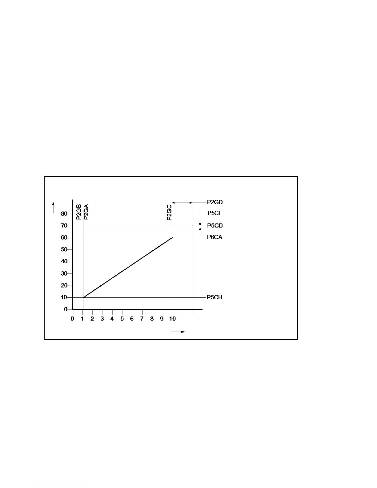
E09.012.246 Manual S-WG
89
11 CONTROLLING OPTIONS AND SETTINGS
11.1 Water heater options
11.1.1 0-10 VDC REMOTE FLOW TEMPERATURE SET POINT
The hot water temperature is controlled by connecting an external 0-10 VDC signal to the water heater (connections 15-16).
P5BB Analogue input Config (0=off 1=temp) (display D1).
This parameter must be set at "1" so the supplied 0-10 V dc signal will control the temperature set point.
Possible settings are:
0 = 0-10V control off
1 = 0-10V temperature set point control active
See also the following graph for the relation between the temperature and the control signal.
offset Legionella
hysteresis Legionella
Legionella temp.
max. setpoint
min. setpoint
0-10V DC control signal [V]
Temperature set point [°C]
off
on
max
Page 89
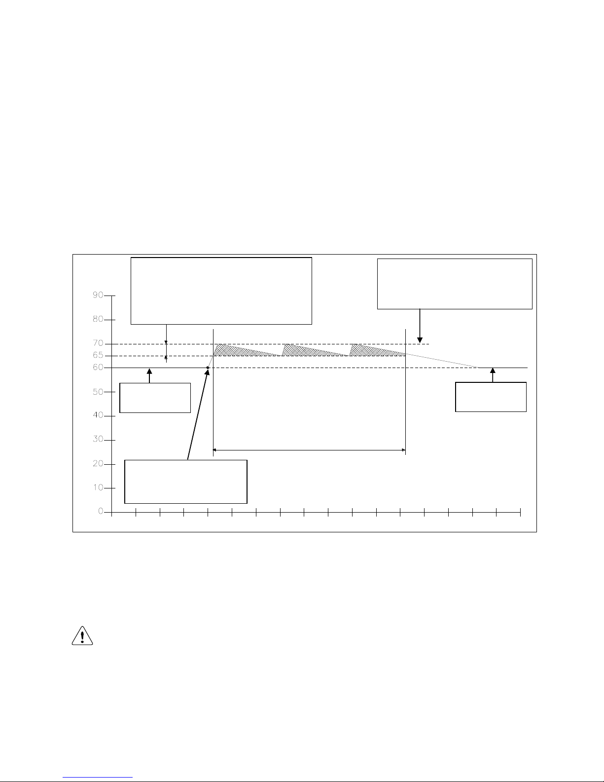
E09.012.246 Manual S-WG
90
11.1.2 ANTI-LEGIONNAIRES’ DISEASE (PASTEURISATION) FUNCTION
To prevent Legionnaires’ disease, the water heater (software) provides a function for heating up the hot water
storage tank (once a week or every day) to a higher water temperature than the normal active hot water set
point. Also the period, that this “higher” water temperature function must be active, can be programmed in P7BV
start time (0:00) and P7BW (8) and is standard switched off.
Also an external 0-10Vdc signal can be used to activate the pasteurisation function this can be done by making
the 0-10V signal higher than 10,2V.
NOTICE: The standard factory setting for this Legionnaires’ disease (pasteurisation) function is “OFF”. To act i-
vate this Legionnaires’ disease function some parameters must be programmed by the manufacturer/supplier.
The starting day and starting time of this Legionnaires’ disease function can be programmed by the control panel
of the water heater and by using a computer, interface cable and the water heater software.
Several parameters are used for this function. Three of these parameters are shown in the following graph.
The settings of these parameters P5CI, P5CJ and P5CD must be programmed according to all applicable anti
Legionnaires’ disease preventing regulations.
The setting of these parameters can only be done by the manufacturer/supplier of the water heater and is possible by the control panel of the unit without the use of a computer.
NOTICE: The use and activation of this function won’t guarantee a Legionnaires’ disease free installation. The responsibility for a Legionnaires' disease free installation remains at the end-user/owner.
P5CI = 5°C
This is the bandwith within which the Legionnaires'
temperature must stay during the programmed duration time period. In this example the temperature is
allowed to fluctuate between 65°C and 70°C during
the anti Legionnaires' function.
P5CJ = 80 min.
This is the duration within which the water tempera-
ture must be between the 65°C and 70°C.
P5CD = 70 °C
This is the maximum temperature during anti
Legionnaires' disease function period.
Normal setting
water temperature.
Start of the anti Legionnaires'
disease program (start day and
time can be programmed).
Normal setting
water temperature.
Time (10 min steps)
Water temperature
Page 90
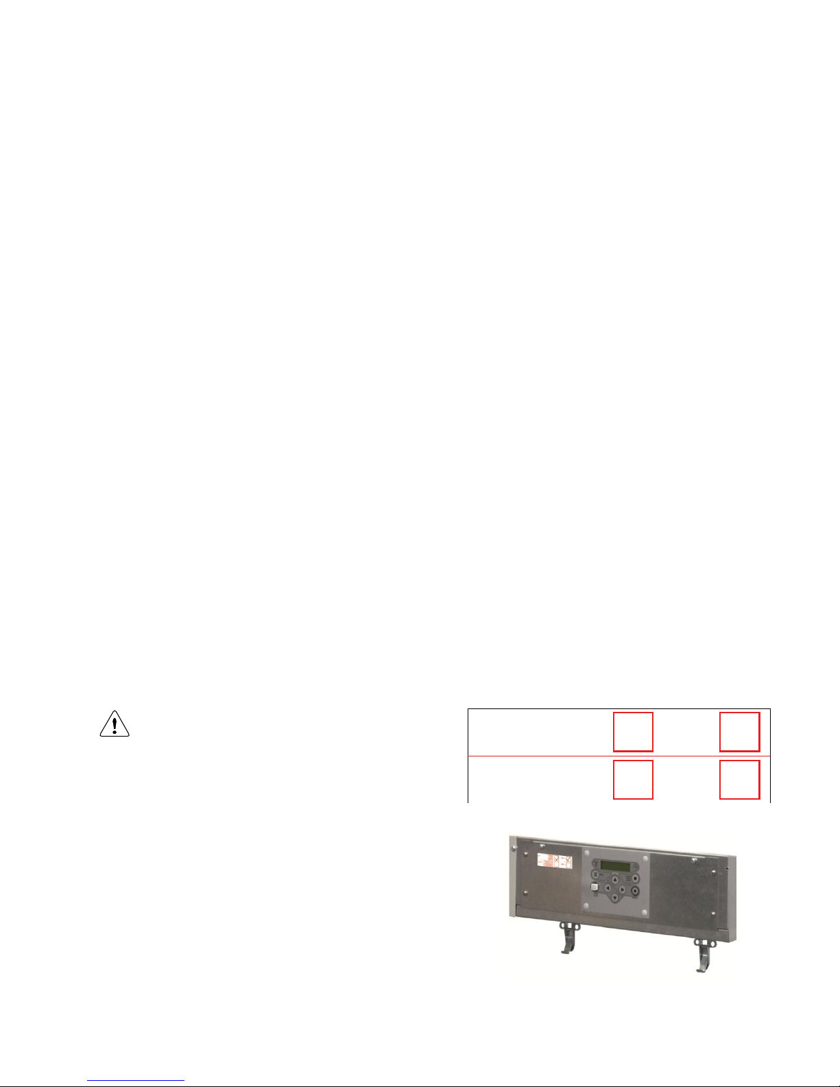
E09.012.246 Manual S-WG
91
11.2 General
The following sections describe some general functions of the water heater and their possible use.
11.2.1 MAX COOLING TIME
The fan will cool down the heat exchanger according to the temperature settings (parameters) of the software.
With this cooling parameter the maximum run time of the fan can be programmed.
P2LK Max cooling time (display D4) [min.]
The fan will cool the heat exchanger according to parameter P2 LJ, but the fan will never run for cooling longer
than the period programmed with this parameter P2 LK. “0” = cooling function off.
For S1 > local set point P6BA – P2LJ fan starts after 1 minute and stops after 3 minutes
During post pump circulation, no post ventilation takes place.
11.2.2 TEMPERATURE DISPLAY ON/OFF
Selection for showing the measured temperatures in the operation display of the water heater.
P5BJ Temperature display 1=on (display D5)
The measured temperature in the operation display.
0 = not visible
1 = visible
11.2.3 GAS TYPE SELECTION
Settings for gas types: natural gas, propane or butane-propane mixture (B/P).
P4 BD Gas type (0=standard, 1=propane , 2=butane/propane (B/P)) (display D8).
This parameter is set 0 for the common used gas types such as natural gas G20 or G25.
By setting this parameter 1 for propane, fan speed is reduced.
Set this parameter 2 for B/P.
0 = standard gas (e.g: natural gas)
1 = propane
2 = B/P
By each setting, the relevant Soft start settings are automatically adjusted, depending on its main setting P4BE,
see next section § 11.2.4.
In case of gas conversion, paste the corresponding sticker at the appropriate position in the
boiler and mark the square for the used gas type.
Also mark the square, indicating that the correct
value has been set for parameter P4BD.
(In the example on the right, ‘propane’ and ‘P4BD =
1’ have been marked).
PROPANE
PROPAN
PROPANO
PROPAAN
BUTANE/PROPANE
BUTAN/PROPAN
BUTANO/PROPANO
BUTAAN/PROPAAN
P4BD = 1
P4BD = 2
G31
G30/G31
Page 91

E09.012.246 Manual S-WG
92
11.2.4 SOFT START OPTION
Start parameters can be modified to achieve better start behaviour, in case of noise or other difficulties. This is
done by reducing the fan ramp-up speed. Two reduced settings are available (I and II).
P4BE Soft start (0=normal, 1=reduced fan ramp-up speed (I), 2= reduced fan speed ramp-up (II))
(display D9).
0 = normal start-up
1 = reduced fan ramp-up speed (I)
2 = reduced fan ramp-up speed (II)
11.2.5 PUMP MODE (EC TECHNOLOGY)
When using a pump with Electronic Commutation technology and start-stop function, with a separate control
connection, this parameter determines the relay for switching the pump on and off.
P5 BN Pump mode (0=modulating, 1=relay1, 2= relay2, 3= relay3, 4= external relay) (display DA).
Do not use the 230 Vac relay for the main power supply of the pump, but directly connect the pump to
the mains of the boiler.
A modulating pump with PWM control: the power supply is directly connected to the mains, the PWM connection
is connected to CN10, contacts 9 and 18.
Pumps with an on/off control can be switched by one of the relay connections “lock-out”, “burner burning” or
“heat demand”. Choose a connection which is not yet used.
If all these connections are already used, an external 24 V relay can be connected to the PMW output connec-
tion (CN10, 9 + 18). By setting the parameter 4, the PMW signal becomes a start/stop signal: ‘pump ON’ by
PMW 100% (so constantly 24 V). This way, the pump can be controlled via the relay.
0 = PWM 0-100% modulating pump, connection CN10, connector 9 and 18
1 = Start-stop through relay 1, connector 19 and 20 (lock-out)
2 = Start-stop through relay 2, connector 21 and 22 (burner burning)
3 = Start-stop through relay 3, connector 23 and 24 (heat demand)
4 = Start-stop through PWM and external relay, connection CN10, connector 9 and 18
11.2.6 TANK SENSOR SENSITIVITY
P2KH Gradient heat demand detection DHW tank temperature (display BG) [0.1°C]
With S3 in use as tank sensor, it is possible to detect a fast cooling down of the tank through a large DHW flow.
The sensitivity of this sensor can be set in parameter P2KH in tenths of degrees.
Page 92
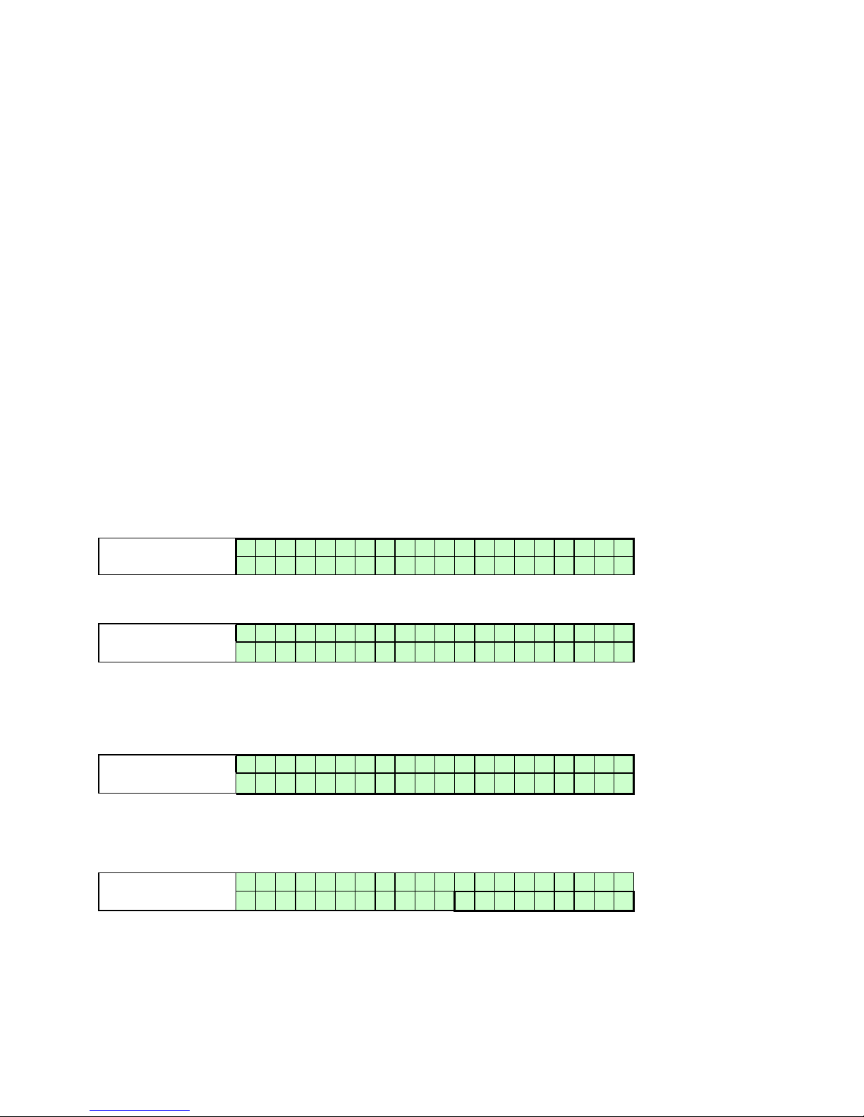
E09.012.246 Manual S-WG
93
12 COMMISSIONING THE WATER HEATER
12.1 First: flushing the water heater with water
After installation of the water heater the first step, before commissioning, is to flush the water heater and the
whole DHW installation with fresh water to remove pollution, debris and other materials that might cause a blocking. This must also be done with installations, where only the water heater is replaced.
12.2 Second: filling & venting the water heater and the system
After flushing the water heater and the installation the system can be filled with fresh water by opening the water
supply valve of the system and opening all the taps that are on the system. The water pressure of the system
should be between a minimum of 1 bar and a maximum of 10 bar, also depending on the applied pressure safety
valve.
The water heater has an automatic air vent situated on top of the water heater (at the roof panel). This vent must
be opened during the filling of the water heater and the DHW system to make sure that no air/oxygen is trapped
in the heat exchanger of the water heater. NOTICE: Check that the screw cap has been loosened at least one
twist.
Make sure that, during flushing and filling, no water can reach any electrical parts of the water heater.
12.3 Third: check the water flow
Before the water heater will be started, be sure that the pump is functioning and that there is a water flow over
the heat exchanger. Check the electrical power supply of the water heater. When this is connected correctly, the
display will show:
Display message
B o i l e r o f f
Reason
Water heater is not active. To activate the water heater press [ON/OFF]
button for 6 seconds.
Display message
W A T R H T R : b o i l e r o f f
> > > : 1 2 3 . 4 ° C ( 1 2 3 . 4 ° C
)
Reason
Water heater is not active. To activate the water heater press [ON/OFF]
button for 6 seconds.
Activate the water heater by pressing the ON/OFF button for at least 6 seconds. After this the following display
will appear:
Display message
W A T R H T R : N o d e m a n d
> > > : 1 2 3 . 4 ° C ( 1 2 3 . 4 ° C
)
Reason
Water heater is active, but there is no heat demand.
When there is no water present in the water heater or the water pressure is too low, the water heater will go into
lock-out and will show a corresponding message in the display.
Display message
W a t e r p r e s s u r e f a u l t 9 9 9 , 5 h r
s
Reason
Water pressure is too low or too high.
Page 93
E09.012.246 Manual S-WG
94
By pressing the [SERVICE] button of the water heater, the water heater can be started without a heating demand. The water heater will start to fire and also the pump will start to run. Firing of the water heater without a
water flow (but filled with water!) will cause the so called “boiling noises”. Check during this “service function”
operation also the flow and return temperatures of the water heater by pressing the [◄] button once. The temperature difference of the flow and return must be at least 13ºC and maximum 25ºC. This temperature difference
indicates that there is a (enough) water flow over the water heater; this water flow prevents the heat exchanger
of possible damage caused by a thermal overload.
Flow monitoring
Another safety feature of the water heater, to make sure that there is enough water flow over the water heater, is
the monitoring of the flow and return temperatures (T1 and T2). When the temperature difference (delta T) between flow and return exceeds a certain (set) value (load dependent), the following warning messages will be
shown in the display.
Display message
T 1 - T 2 h i g h
9 9 9 , 5 h r
s
Reason
Temperature difference T1-T2 has exceeded the blocking value, as set in the parameters.
Display message
D e l t a D i r e c t b l o c k
9 9 9 , 5 h r
s
Reason
The temperature difference between flow and return has exceeded the blocking
value
When this temperature difference exceeds the lock-out setting, the water heater will switch off and the following
lock out code will be shown at the display.
Display message
F l o w R e t u r n d t f a u l t F16 p u m p o n 9 9 9 , 5 h r s
Reason
Temperature difference between flow and return has exceeded the blocking value.
Parameters P2CO, P2CR until P2CV.
When these messages appear and/or the water heater will lock out, it means that there is not enough flow over
the water heater. In this case check the functioning of the pump.
The water heater has a built in water pressure switch. If water pressure of the system drops under a certain limit,
the water heater will go in a lock-out.
During and after the commissioning of the water heater, the operation of the water heater pump must be
checked, before leaving the installation room.
NOTICE: Always check the running of the pump before firing the water heater.
Page 94
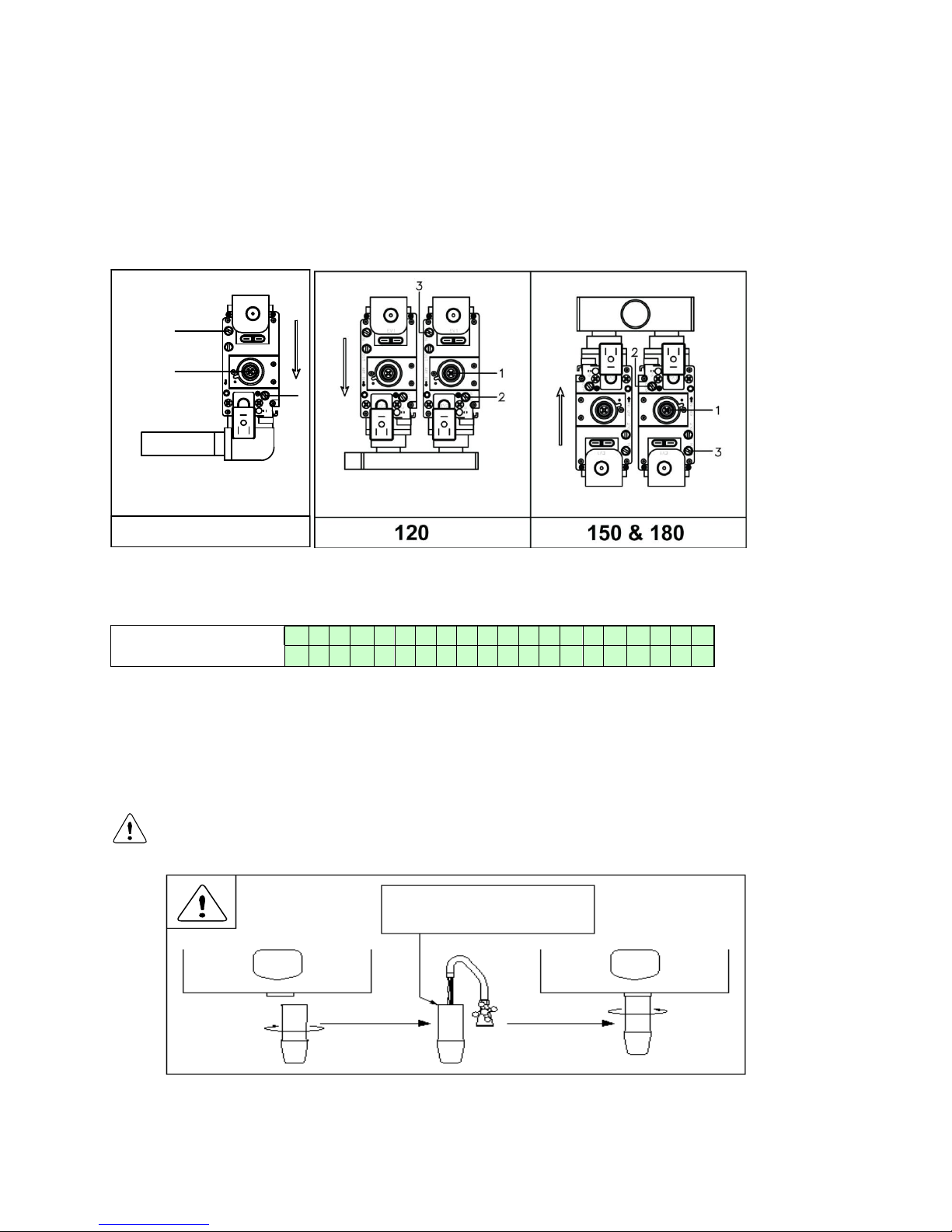
E09.012.246 Manual S-WG
95
13 STARTING THE WATER HEATER
13.1 General
Check the gas pressure available at the gas connection pipe of the water heater. Use the pressure nipple (3) of
the gas safety valve for this measurement. The gas pressure for the water heater, to operate properly under the
correct load, must be at least 20 mbar.
The graphs below show the position of the pressure nipple (3) for the complete water heater range.
13.2 Firing for the first time
After the commissioning of the water heater and the described previous actions, the water heater display will
show the following graph.
Display message
W A T R H T R : N o d e m a
n
d > > > 1 2 3 . 4 ° C ( 1 2 3 . 4 ° C
)
Reason
Water heater is active, but there is no heat demand.
The display describes:
The actual operation
If a heat demand is activated
The temperature setting
The temperature measured
When mounting the bottom part of the siphon, before commissioning the water heater and/or after
maintenance, the siphon must ALWAYS be completely filled with water.
This is a safety measure: the water in the siphon keeps the flue gases from leaking out of the
heat exchanger via the condensate drain.
When the water heater receives a heat demand the electronics will start the operation of the water heater. Before the water heater is used, the water heater burner must be adjusted and set at the minimum and maximum
load.
80 & 100
P
I
L
O
T
9-I
IN OUT AIR I N
EV 2
EV 1
3
1
2
The siphon must always be filled
with water to the edge before
placing back on the unit
Page 95
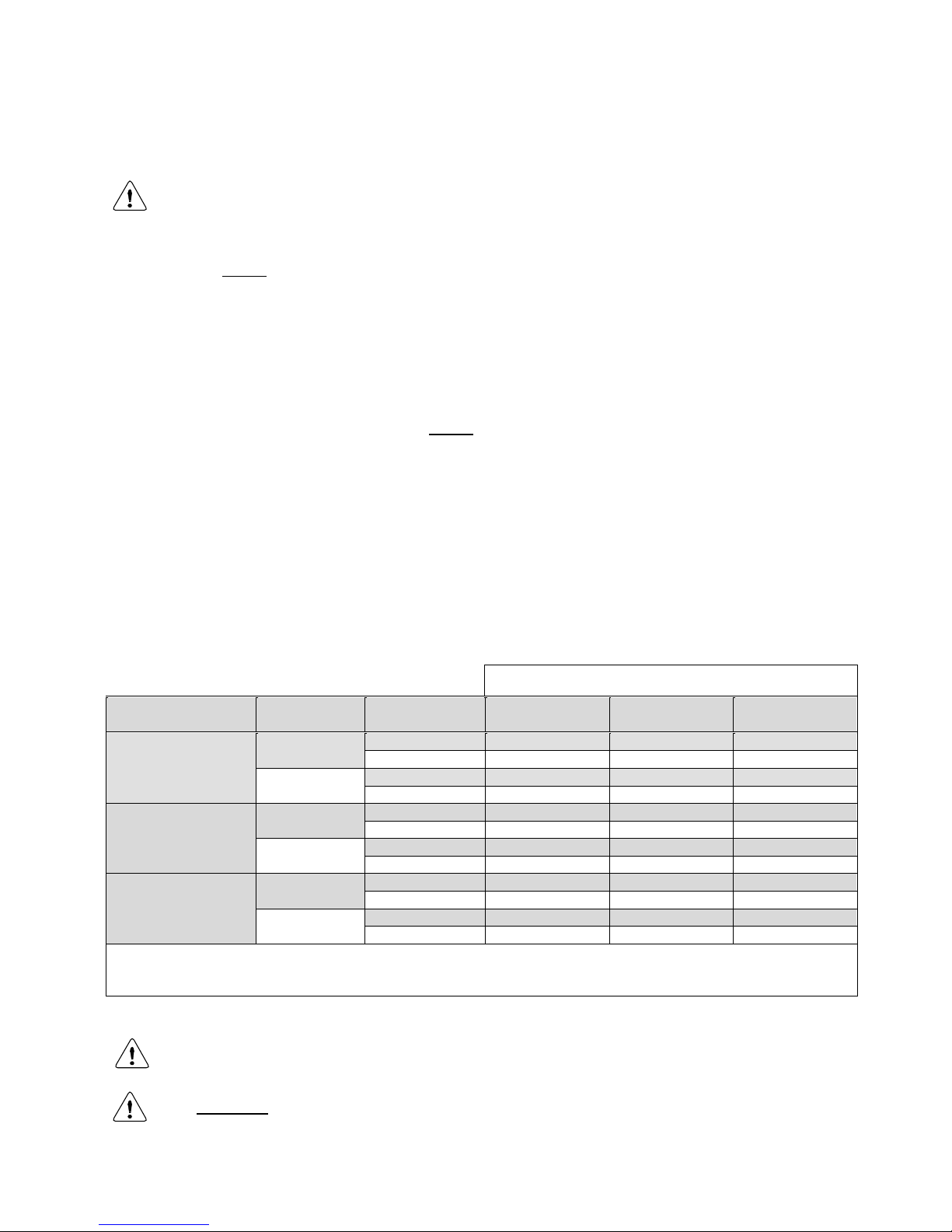
E09.012.246 Manual S-WG
96
14 ADJUSTING AND SETTING THE BURNER
Before carrying out any adjusting of the burner, carefully read this complete chapter.
14.1 Introduction
The burner must always be adjusted in the next situations:
A. - A new water heater is installed
- As part of a service/maintenance check, in case the CO2 values turn out to be incorrect
Adjustment procedures for situation A are described in § 14.2.
B. - The gas control safety valve has been (re)placed
- Another type of gas is applied: gas conversion
Adjustment procedures for situation B are described in § 14.3.
In either of the four cases described in A and B, always check the gas/air ratio of the combustion figure (CO2) at
maximum and minimum input. First set the water heater at maximum load and subsequently at minimum load,
and repeat if necessary.
Set-up of this chapter:
First, all necessary values are given in three tables in § 14.1.1. A drawing of the gas valve(s) and setting screws
is given in § 14.1.2 on the next page. In § 14.1.3 a general scheme, conform which the adjustments must be
carried out, is presented in table form. After that, in §§ 14.2 and 14.3, a thorough description is given of how to
proceed in cases A and B respectively. In § 14.4, finally, two main procedures used in the previous sections are
described in detail.
14.1.1 ADJUSTMENT TABLES
Tables 2 and 3 see next page
Maximum fan speed has to be reduced to convert the water heater into a butane (B/P) appliance.
For adjustment use CO2 tolerance of ± 0.1 % (for O2 this is ± 0.2 %).
Table 1
gas type:
water heater type
load
output
nat.gas
G20 1/ G25 1
propane
G31 1
butane (B/P)
G30
1, 3
S-WG 80-120 2
max. load
CO2 (%)
9.0
10.3
10.4
O2 (%)
4.8
5.2
5.3
min. load
CO2 (%)
8.7
9.3
9.3
O2 (%)
5.3
6.7
6.9
S-WG 150 2
max. load
CO2 (%)
9.0
10.4
10.5
O2 (%)
4.8
5.0
5.2
min. load
CO2 (%)
8.7
9.3
9.3
O2 (%)
5.3
6.7
6.9
S-WG 180 2
max. load
CO2 (%)
9.0
10.5
10.6
O2 (%)
4.8
4.7
4.9
min. load
CO2 (%)
8.7
9.3
9.3
O2 (%)
5.3
6.7
6.9
1
Cf. EN437
2
All values are measured without front panel.
3
Fan settings must be changed by altering parameter P4BD (display D8) (only by a skilled mechanic)
Page 96
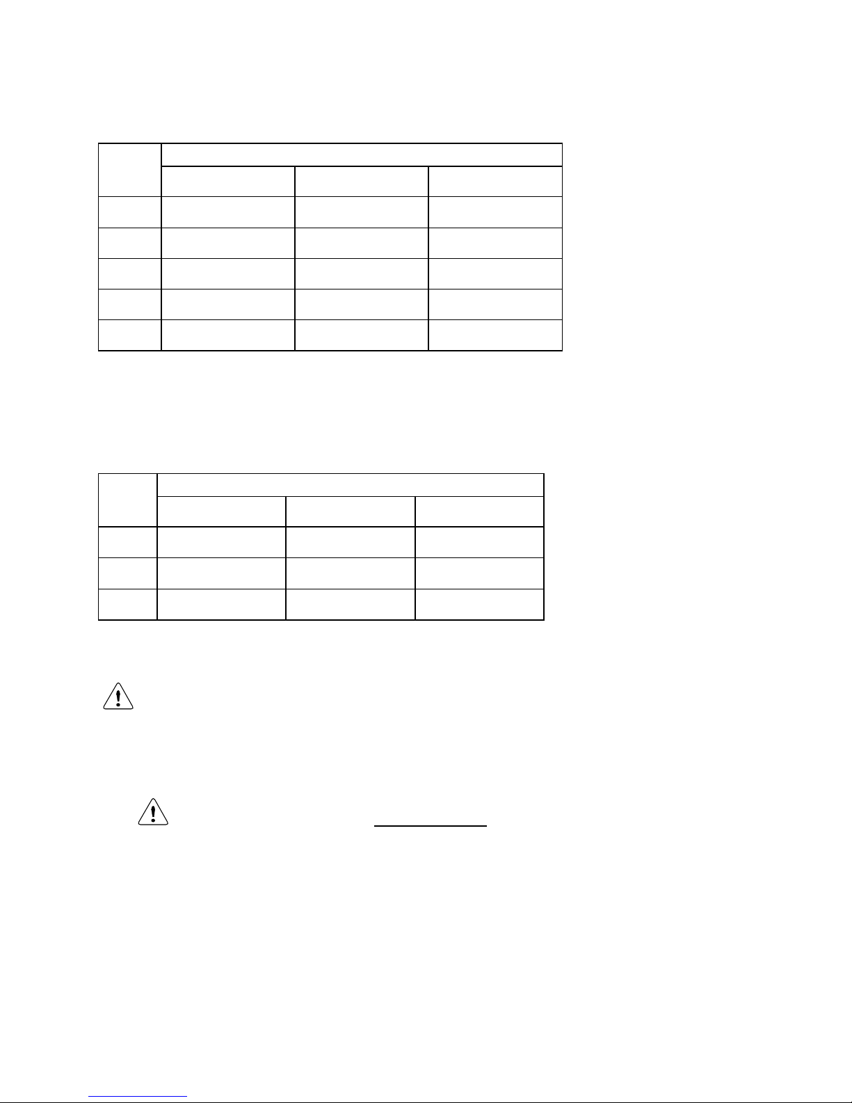
E09.012.246 Manual S-WG
97
Table 2
pre adjustment settings gas valve for BIC water heaters
water
heater
type
number of turns open (counter clockwise)
nat. gas G20 / G25
propane G31
butane G30
S-WG
80
1.5
0.75
0.5
SWG100
3.5
1.5
1.25
SWG120
2.25 *
1 *
0.75 *
SWG150
2.25 *
1 *
0.75 *
SWG180
4.25 *
2.25 *
2 *
* Both gas valves must be opened this number of turns.
Table 3
Contact your supplier for the right settings when converting to a not mentioned type of gas.
Pressure adjustment settings LEFT valve
water
heater
type
“p-out” pressure at gas valve
nat. gas G20 / G25
propane G31
butane G30
S-
WG120
-2 to 0 Pa
-4 to -2 Pa
-5 to -3 Pa
S-
WG150
-2 to 0 Pa
-7 to -5 Pa
-8 to -6 Pa
S-
WG180
-2 to 0 Pa
-7 to -5 Pa
-8 to -6 Pa
The maximum fan speed has to be reduced to convert the water heater into a butane (B/P) appliance.
Set parameter P4BD.
14.1.2 SETTING SCREWS GAS VALVE(S): DRAWINGS
NOTICE: Do NOT mistake the screw marked ‘PILOT’ for screw 2.
Screw 2 is the SMALL screw immediately next to the pilot screw.
Page 97
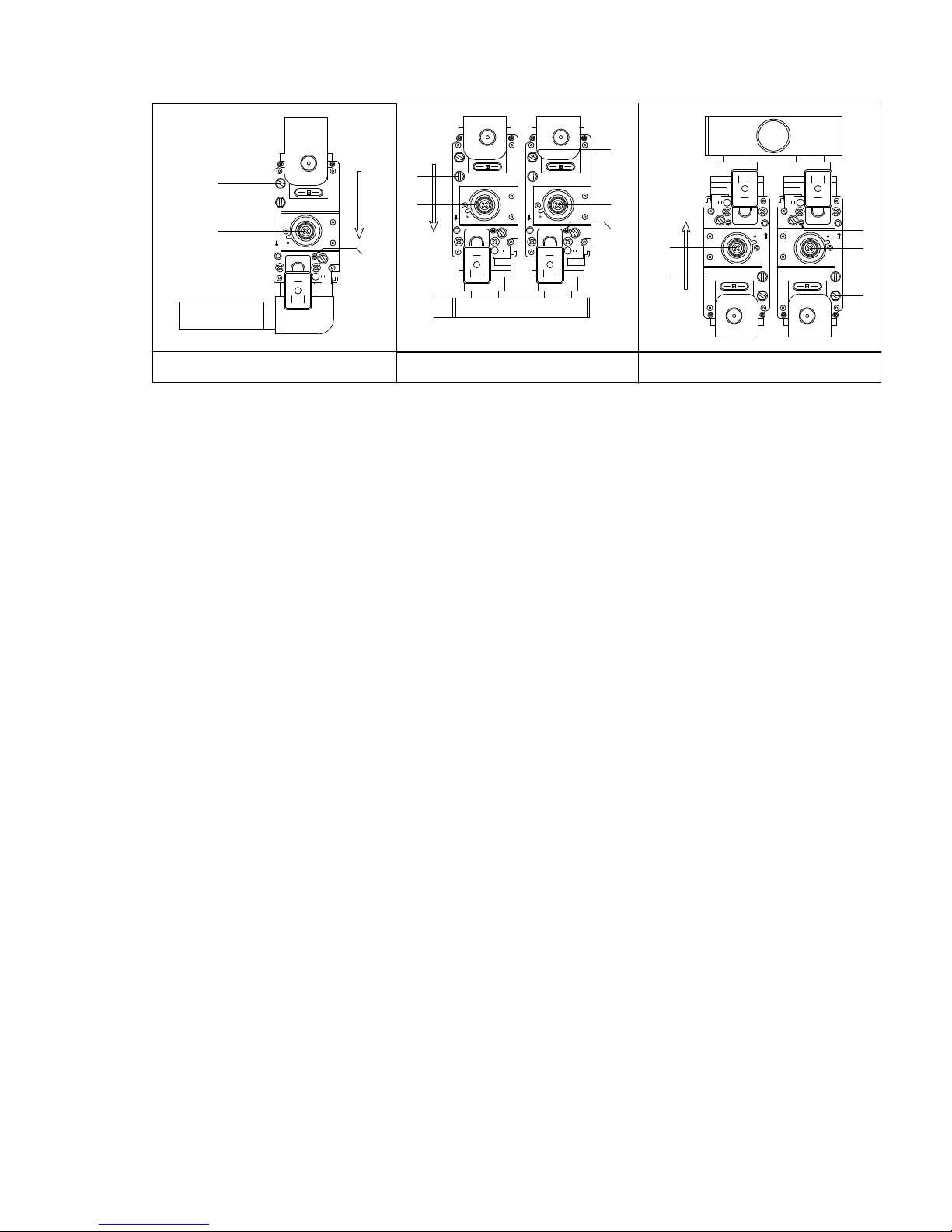
E09.012.246 Manual S-WG
98
80 & 100
150 & 180
120
P
I
L
O
T
9-I
IN OUT AIR IN
EV2
EV1
P
I
L
O
T
9-I
IN OUT AIR IN
EV2
EV1
P
I
L
O
T
9-I
IN OUT AIR IN
EV2
EV1
P
I
L
O
T
9-I
IN OUT AIR IN
EV2
EV1
P
I
L
O
T
9-I
IN OUT AIR IN
EV2
EV1
3
1
2
3
1
2
3
1
2
4
1
1
4
Page 98
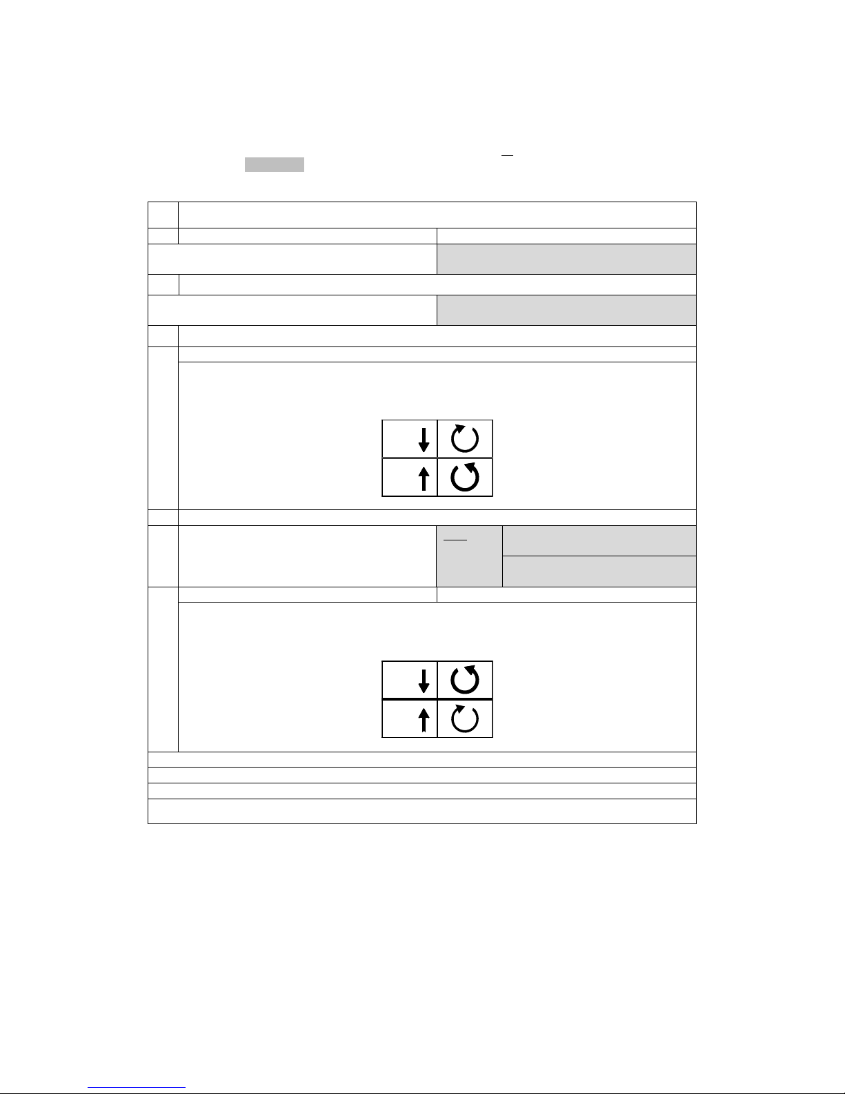
E09.012.246 Manual S-WG
99
14.1.3 ADJUSTMENT ACTIONS: GENERAL SCHEME
General scheme for adjustment of the gas valve(s). Check this scheme for an overview.
To complete all necessary adjustments in right order, follow case A or B top-down through the scheme (B involves a few extra steps (grey fields)):
GENERAL SCHEME SETTING STEPS
case A
case B
continue ↓
first close (both*) screw(s) [2], then set
them in accordance with table 2
SWITCH TO SERVICE MODE
continue ↓
If burner doesn’t start, open (RIGHT*)
screw[2] ¼ turn extra
setting at maximum load
procedure 1
[▲] set burner at maximum load
measure CO2 at flue gas outlet;
use (RIGHT*) screw [2] to
match value with table 1
setting at minimum load
continue ↓
only
SWG120,
150, 180
[▼] set burner at minimum
load
use LEFT screw [1] to match
“p-out” with table 3
procedure 2
[▼] set burner at minimum load
measure CO2 at flue gas outlet;
use (RIGHT*) screw [1] to
match value with table 1
repeat procedure 1
repeat procedure 2
keep repeating until values match table values best
Water heater returns to NORMAL MODE after 40 min. OR by pressing [SERVICE] button
* in case of a double valve (S-WG120, 150 and 180)
For an extensive description consult the next two sections (choose which is applicable, A or B):
CO2
[2]
CO2
[2]
CO2
[1]
CO2
[1]
Page 99

E09.012.246 Manual S-WG
100
14.2 Adjusting in case of a new water heater, or after service (case A)
14.2.1 GENERAL REMARK
For all adjusting steps under A the following must be applied: as long as measured CO2 values differ less than
0.3% from the table values, no adjustment is necessary, because this deviation is typical for the process (O2
values: ± 0.5%). If, however, larger deviations are measured, adjustment now must be made until the table value
is reached within max. 0.1% deviation (O2 values: ± 0.2%).
14.2.2 ADJUSTING AT MAXIMUM LOAD
Adjust at maximum load by carrying out procedure 1, see p.102 .
14.2.3 ADJUSTING AT MINIMUM LOAD
Adjust at minimum load by carrying out procedure 2, see p.102.
14.3 Adjusting after gas valve replacement, or in case of gas conversion (case B)
The maximum fan speed has to be reduced to convert the water heater into a butane (B/P) appliance
(set parameter P4BD).
14.3.1 GENERAL REMARKS
In case B, a distinction is made between the setting of boilers containing a single valve (S-WG80-S-WG100) and
boilers containing a double valve (S-WG120-S-WG180).
All adjustments must result in CO2 percentages within a bandwidth of max. ± 0.1% deviation from the table values (O2 values: ± 0.2%).
14.3.2 ADJUSTING AT MAXIMUM LOAD S-WG80 / S-WG100
The water heaters S-WG80 and S-WG100 all have single gas valves, see the drawings on page 97.
First, turn setting screw [2] of the gas valve clockwise until you feel resistance. This means that the valve
is closed, do not try to tighten the screw any further.
Now turn screw [2] counter clockwise (open), according to the number of turns in table 2 for the used wa-
ter heater and gas type.
After this, adjust at maximum load by carrying out procedure 1 on p.102.
If the burner doesn’t start up in service mode, turn screw [2] a quarter turn counter clockwise further open, and
try again.
14.3.3 ADJUSTING AT MINIMUM LOAD S-WG80 / S-WG100
Adjust at minimum load by carrying out procedure 2 on p.102.
IMPORTANT: Toggle between high fire and low fire to make fine-tuning adjustments (adjusting the minimum
setting affects the maximum setting and contrariwise).
14.3.4 CHECKING AND ADJUSTING AT MAXIMUM LOAD S-WG120 / S-WG150 / S-WG180
The water heaters S-WG120, S-WG150 and S-WG180 all have double gas valves, see the drawings on page
97.
First connect a manometer to “p-out” = measuring point [4] of the left gas valve (see drawing).
Now, turn setting screws [2] of both gas valves clockwise until you feel resistance. This means that the
valves are closed, do not try to tighten the screws any further in the closed position.
After this, turn screws [2] of both left and right hand gas valve counter clockwise (open), according to the
number of turns in table 2 for the used water heater and gas type.
From now on only use the right hand gas valve for adjustments on high fire.
Adjust the right hand valve at maximum load by carrying out procedure 1 on p.102.
If the burner doesn’t start up in service mode, turn screw [2] a quarter turn counter clockwise further open, and
try again.
Page 100
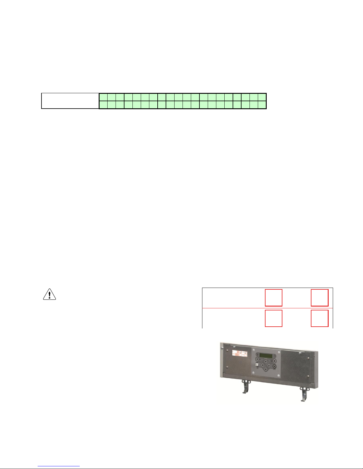
E09.012.246 Manual S-WG
101
14.3.5 CHECKING AND ADJUSTING AT MINIMUM LOAD S-WG120 / S-WG150 / S-WG180
Adjusting these water heaters at minimum load in case B involves extra measurements, to get both valves balanced:
Use the [▼] button to decrease the actual load of the service (percentage) to the minimum. The following screen
will appear:
Display message
W A T R H T R : S e r v i c e 2 6
%
> > > 1 2 3 . 4 ° C ( 1 2 3 . 4 ° C
)
Water heater is activated and operates at service mode at 26% (minimum).
See table 3 for pressure settings “p-out” gas valve for the used water heater and gas type.
Use screw [1] on the left hand gas valve to adjust the measured pressure at “p-out” to the right value according
to table 3. Be sure the manometer has been zeroed out prior to making this setting.
Below, the influence of turning screw [1] is described.
Turning counter clockwise
Turning clockwise
less gas
more gas
a drop in CO2
a rise in CO2
a drop in measured pressure at “p-out”
a rise in measured pressure at “p-out”
After “p-out” has been set cf. table 3, use only the right hand screw [1] for setting the CO2 at low fire.
Adjust the right hand valve at minimum load by carrying out procedure 2 on p.102.
Again, toggle between high fire and low fire to make fine-tuning adjustments (adjusting the minimum setting affects the maximum setting and contrariwise).
If the valves have been set correctly, “p-out“ left should equal “p-out“ right. As an additional test, one could check
this by measuring “p-out“ at the RIGHT valve, i.e. at measuring point 4 on the right valve (not denoted in the
drawings on page 97).
This pressure should be in the same range of pressure as the left valve, so in accordance with table 3 again.
If, after all setting steps have been carried out properly, the values of left and right “p-out“ are still very different,
contact your supplier.
In case of gas conversion, paste the corresponding sticker at the appropriate position in the
boiler and mark the square for the used gas type.
Also mark the square, indicating that the correct
value has been set for parameter P4BD.
(In the example on the right, ‘propane’ and ‘P4BD =
1’ have been marked).
PROPANE
PROPAN
PROPANO
PROPAAN
BUTANE/PROPANE
BUTAN/PROPAN
BUTANO/PROPANO
BUTAAN/PROPAAN
P4BD = 1
P4BD = 2
G31
G30/G31
 Loading...