

Strebel SP 150, SP 170, SP 300, SP 400, SP 220 Installation Manual
...
21 0- 03 88 - O c to be r 20 12
0694
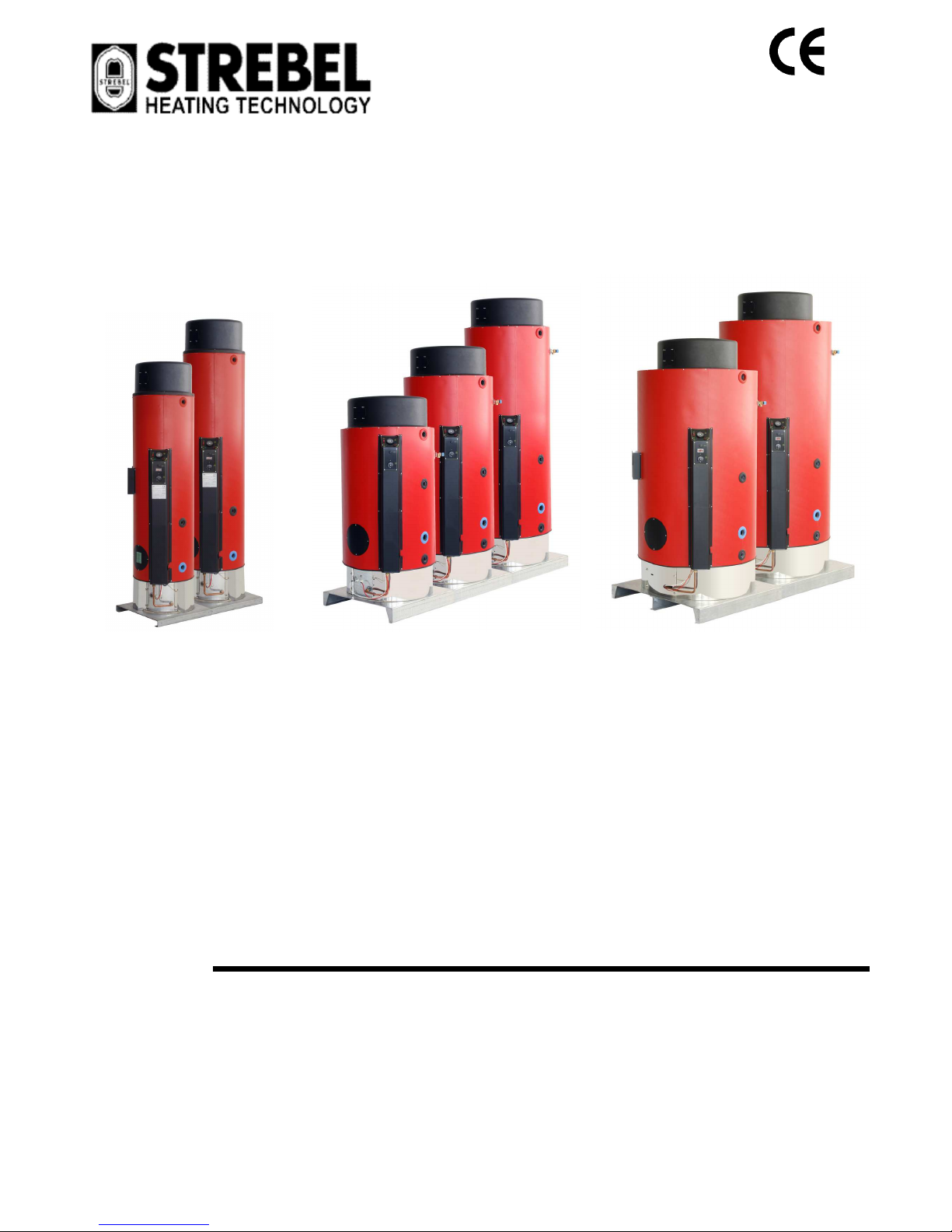
SP 150
SP 170
SP 220
SP 300
SP 400
SP 600
SP 800
Gas fired storage water heaters
with sealed combustion chamber (C type)
and forced flue draft
MANUAL OF INSTALLATION
GENERAL INFORMATION AND CHARACTERISTICS
INSTRUCTIONS TO THE INSTALLER
INSTRUCTIONS TO THE USER

210-0388 - Edition October 2012
WARNING
••••
The following instruction book is an integral and essential part of the
appliance and it has to be kept with care near the appliance, for any
further consultation.
••••
The appliance has been conceived for hot water production: any
other use of it has to be considered dangerous and not suitable.
••••
The appliance is not to be installed in damp rooms and it has to be
protected from water splashes and other liquids, to avoid anomalies to
electrical and thermal devices.
••••
The installation has to be made by professional qualified people, who
are responsible for the respect of all safety regulations in force. An
incorrect installation, caused by a non-observance of manufacturer’s
instructions, can cause damages to people, animals or things for which
the manufacturer cannot be considered responsible.
••••
The appliance, as switched on, has to be tested by an Authorised aftersale service.
••••
Packaging parts (plastic bags, polystyrene, wood, clips, nails,..) can be
harmful to children and should be carefully disposed of
immediately.
••••
Read carefully the instructions and the advice concerning safety,
installation, use and maintenance contained in this booklet.
••••
If the appliance is sold or transferred to a new owner, make sure that
this booklet stays with the appliance, so that the new owner or the
installer can consult it.
••••
Do not place anything upon the appliance.
••••
To avoid damages caused by low temperatures, if the appliance has to
be left unused for a long period in a non-heated room, it is
recommended to empty the unit completely. The manufacturer is not
responsible for faults, break downs or for water leakage from the plant
caused by low temperatures.
••••
To comply with the warranty terms, we advise you to adhere to the
following instructions and to use only original spare parts and kits,
supplied by the manufacturer.

210-0388 - Edition October 2012
INDEX ........................................................................ page
1.1 TECHNICAL DATA 3
1.2 APPLIANCE CLASSIFICATION 3
1.3 PACKAGING CONTENT 4
1.4 OPERATIONAL AND FUNCTIONAL DESCRIPTION 4
1.5 CONTROL AND SAFETY DEVICES 5
1.6 DIMENSIONS AND CONNECTIONS 7
2.1 REFERENCE REGULATIONS 9
2.2 RECOMANDATIONS FOR THE INSTALLATION 9
2.3 FLUE HOOD INSTALLATION 9
2.4 WATER CONNECTIONS 10
2.5 GAS CONNECTIONS 11
2.6 GAS SUPPLY SETTING 11
2.7 GAS SUPPLY CONVERSION 11
2.8 WIRING 12
2.9 CONNECTION OF SEVERAL APPLIANCES 12
2.10 FLUE SYSTEMS 13
2.11 WIRING 15
2.12 STARTING THE APPLIANCE 16
2.13 FAULT FINDING 16
3.1 RECOMMENDATIONS FOR THE USER 17
3.2 STARTING THE APPLIANCE 17
3.3 TURNING OFF THE APPLIANCE 17
3.4 MAINTENANCE 17
3.5 WARRANTY 17
3.6 FREQUENTLY ASKED QUESTIONS 18
1 – GENERAL INFO RMAT IO N AN D CHARACTERISTICS
-
3 -
210-0388 - Edition October2012
1.1 TECHNICAL DATA
mod.
150 170 220 300 400 600 800
Nominal storage capacity litres 145 160 220 300 395 585 740
Nominal input kW 18.0 19.0 25.0 29.0 29.0 31.0 31.0
Nominal output kW 16.9 17.9 23.5 27.3 27.3 29.1 29.1
Combustion efficiency - 94% 94% 94% 94% 94% 94% 94%
Flue mass g/s 9,0 9,5 12,5 14,0 14,8 16,0 16,4
Flue temperature °C 109 95 109 115 97 104 103
Recovery time (∆T = 25 °C)
min 16 17 16 19 26 35 44
Recovery time (∆T = 45 °C)
min 28 30 29 35 46 64 79
Continuous output (∆T = 25 °C)
lt/hr 551 575 817 938 908 981 1013
lt/min 9,2 9,6 13,6 15,6 15,1 16,4 16,9
Continuous output (∆T = 45 °C)
lt/hr 306 320 454 521 504 545 563
lt/min 5,1 5,3 7,6 8,7 8,4 9,1 9,4
Natural gas input rate (G20 - 20 mbar) m3/h 1,91 2,01 2,65 3,07 3,07 3,28 3,28
n° injectors - 11 11 16 16 16 16 16
injectors diameter mm 1.20 1.25 1.25 1.25 1.25 1.25 1.25
Burner pressure mbar 10.3 10.5 10.0 12.2 12.2 12,1 12,7
LPG input rate (G30/31 28-30/37 mbar) Kg/h 1,40 1,50 2,00 2,30 2,30 2,40 2,40
n° injectors - 11 11 16 16 16 16 16
injectors diameter mm 0.70 0.70 0,65 0.72 0.75 0.75 0.75
Power consumption 230 V ~ 50 Hz (IP20) W 67 67 67 67 67 67 67
Max working head Mpa 0,6 0,6 0,6 0,6 0,6 0,6 0,6
Empty weight Kg 128 141 220 265 309 278 324
Filled weight Kg 273 301 440 565 704 863 1064
Tests carried out in standard conditions (15 °C / 1013 mbar)
1.2 APPLIANCE CLASSIFICATION
DEFINITION
These appliances are classified as: "Gas fired water
heaters with sealed combustion chamber and atmospheric
burner, equipped with fan in the combustion circuit”.
TYPE
As classed by the European Regulation EN483, the type of
the appliance can be C12, C32, C42, C52, C62, C82
depending on the system used for the air supply and the
exhaust gas evacuation.
Here below a short description of the different types:
C12
The air intake and the flue outlet are
done by means of a horizontal coaxial
duct or through orifices sufficiently
close one to the other to be located in
almost identical wind conditions.
C32
The air intake and the flue outlet are done
by means of a vertical coaxial duct.
C42
The appliance is connected to a collective
duct consisting of a duct for the air supply
and a duct for the flue discharge. The
orifices of this system are concentric or
sufficiently close one to the other to be
located in almost identical wind
conditions.
C52
The air intake and the flue outlet have to
be located in different pressure
conditions.
C62
The appliance has to be connected to an
external system for the air supply and the
flue outlet. This external device has to be
approved and sold separately.
C82
The air intake is done by means of
an air terminal, whereas the flue
outlet is done through an individual
or collective chimney.
1 – GENERAL INFO RMAT IO N AN D CHARACTERISTICS
-
4 -
210-0388 - Edition October2012
CATEGORY
The countries of destination and the categories are listed
in the chart here below.
Country
Category
Country
Category
AT I2H,I
3B/P
,II
2H3B/P
BE I
2E+,I3+
,II
2+3+
BG I2H,I
3B/P
, I
3
P
,II
2H3B/P
,II
2H3P
CH I2H,I
3B/P,I3+
,II
2H3B/P
,II
2H3+
CY I2H,I
3B/P,I3B,I3+
,II
2H3B/P
,II
2H3
+
CZ I2H,I
3B/P,I3+
,II
2H3B/P
,II
2H3+
DE I2E,I
3B/P
,II
2E3B/P
DK I2H,I
3B/P
,II
2H3B/P
EE I2H,I
3B/P
, I3P,II
2H3B/P
,II
2H3P
ES I2H,I3+,II
2H3+
FI I2H,I
3B/P
,II
2H3B/P
FR I
2E+,I3+
,II
2+3+
GB I2H,I3+,II
2H3+
GR I2H,I
3B/P,I3+
,II
2H3B/P
,II
2H3+
HU I2H,I2S,I
3B/P
,II
2HS3B/P
IE I2H,I3+,II
2H3+
IT I2H,I
3B/P,I3+
,II
2H3B/P
,II
2H3+
LT I2H,I
3B/P,I3+,I3P
,II
2H3B/P
,II
2H3+
,II
2H3P
LU I2E,I3P,II
2E3P
LV I2H,I
3B/P,I3P
,II
2H3B/P
,II
2H3P
MT I2H, I
3B/P,I3B
,II
2
H3B/P
,II
2H3B
NL I2L,I
3B/P
,II
2L3B/P
NO I2H,I
3B/P
,II
2H3B/P
PL I2E,I
3B/P,I3P
,II
2E3B/P
,II
2E3P
PT I2H,I
3B/P,I3+
,II
2H3B/P
,II
2H3+
RO I2E,I2H,I
3B/P
,II
2E3B/P
,II
2H3B/P
SE I2H,I
3B/P
,II
2H3B/P
SI I2H,I
3B/P,I3P,I3+
,II
2H3B/P
,II
2H3
P
,II
2H3
+
SK I2H,I
3B/P,I3P,I3+
,II
2H3B/
P
,II
2H3P
,II
2H3+
TR I2H,I
3B/P
,II
2H3B/P
The atmospheric burner can operate on gas:
Of the second family (group E, E+, H, L, S)
Of the third family (group B, P, B/P, 3+)
IMPORTANT
This installation, use and maintenance manual is valid
only for Italy.
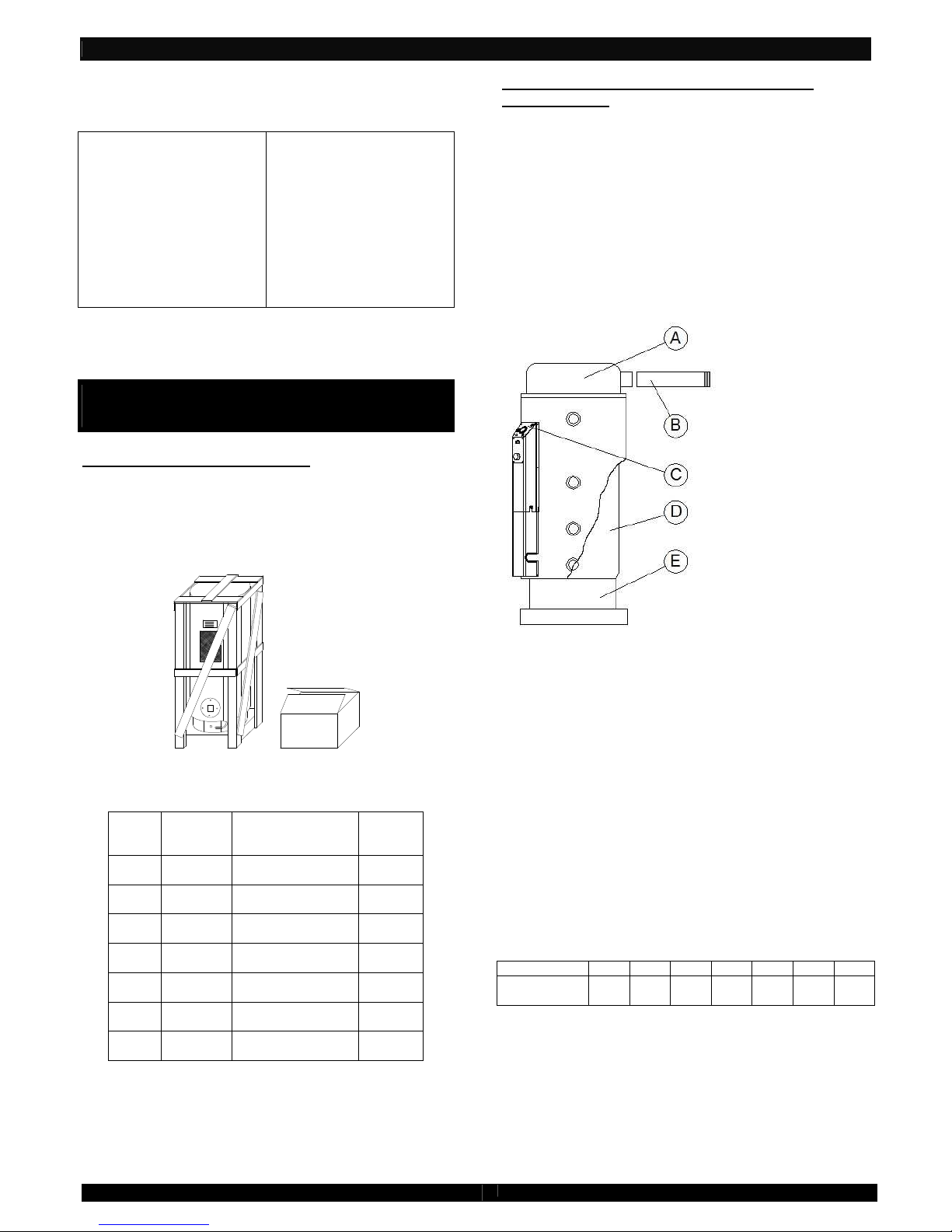
1.3 PACKAGING CONTENT
The appliance is delivered packaged in a wood cage with
appropriate protection. A second cardboard box contains
the flue hood (with the inside fan), the flue outlet carrier
and the screws necessary for the flue hood installation.
An envelope, provided on the frontal casing of the
appliance, contains this manual and the warranty
certificate.
fig_1-03: packaging
Dimensions and gross weight of the heaters
mod. parcels
n°
dimensions
LxPxH
(cm)
weight
(kg)
150 2
58 x 58 x 175
46 x 46 x 23
119
9
170 2
58 x 58 x 195
46 x 46 x 23
132
9
220 2
78 x 78 x 141
67 x 67 x 23
211
9
300 2
78 x 78 x 176
67 x 67 x 23
256
9
400 2
78 x 78 x 211
67 x 67 x 23
300
9
600 2
98 x 98 x 180
67 x 67 x 23
289
9
800 2
98 x 98 x 210
67 x 67 x 23
335
9
1.4 OPERATIONAL AND FUNCTIONAL
DESCRIPTION
The purpose of the appliance is to allow the heat exchange
between the gas combustion products, burned inside the
combustion chamber, and the water stored in the tank.
The combustion is completely sealed inside the
combustion chamber: the air supply and exhaust gases
outlet are made outside the room where the appliance is
located. The sealed combustion chamber is placed at the
bottom of the heater, under the water tank.
A flue hood is placed on the top of the heater: a fan,
placed afterwards the combustion chamber, ensures the
flue gases evacuation and the proper air supply to the
burner. Inside the tank there are some flue tubes that carry
air to the combustion chamber and flue gases back to the
flue hood, increasing also the heat exchange.
LEGEND:
A. Flue hood
B. Flue kit
C. Instrument
control panel
D. Tank
E. Combustion
chamber
fig_1-04:
FLUE HOOD
A fan, placed inside the flue hood, ensures the air supply
and flue gases outlet. The flue hood can be orientated with
any angle. In case of bad operation of the fan or
obstruction of the flue pipes, a differential pressure switch,
which the flue hood is equipped of, turns off the gas supply
to the burner.
TANK
The tank is made of thick sheet steel highly resistant to
pressure. Each storage tank is internally lined with a
vitreous enamel coating (baked at more than 850° C). This
coating ensures a high chemical resistance (unassailable
from organic solvents and many other chemical
substances), an excellent abrasion resistance (low friction)
and a very good thermal stability (the opal glass on steel
resists up to 500°C; moreover frost and cold have no
effects). Generally speaking, the coating makes the
working life of the tank longer and water healthier.
A clean out and inspection door allows an easy inspection
and cleaning of the tank.
mod. 150 170 220 300 400 600 800
Ø Flange
(mm)
85 85 120 120 120 120 120
COMBUSTION CHAMBER
The combustion chamber is placed at the bottom of the
heater. The atmospheric burner and the flame detection
system are housed inside the combustion chamber that is
completely sealed.
INSTRUMENT CONTROL PANEL
All the devices needed to control and adjust the normal
operation of the heater are located on the instrument
control panel: control thermostat, ON / OFF switch, lockout lamp/reset push-button and thermometer.
1 – GENERAL INFO RMAT IO N AN D CHARACTERISTICS
-
5 -
210-0388 - Edition October2012
FLUE SYSTEMS
(Installing the original kits supplied by the
manufacturer of the appliance is compulsory)
The flue system has to be chosen according to the
installation requirements. It connects the flue hood to the
outside of the building, supplying air to the burner and
discharging flue gases.
1.5 CONTROL AND SAFETY DEVICES
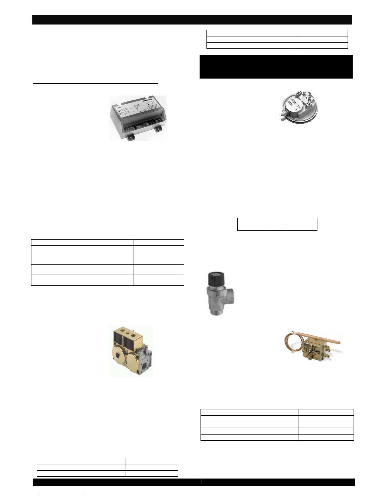
CONTROL BOX
fig_1-05-01:
Control box
The control box supervises the opening and closing of the
gas valve and the burner ignition. As it gets power supply
from the adjustable thermostat, first of all it checks if the
differential pressure switch is operating correctly.
If the differential pressure switch is operating badly, the
burner ignition is not allowed. Otherwise, a pre-purge
period of the combustion chamber elapses before the builtin igniter and gas valve are energised. If the flame is not
established within the safety time, the control box LOCKS
OUT. In this case, in order to relight the heater, wait a few
seconds and then reset the control box, pressing the reset
push-button on the instrument control panel. Flame is
detected by ionisation, by means of a special detection
electrode placed on the burner.
It is EC approved (according to EN 298).
Technical features
Electrical supply 220/240 V - 50 Hz
Room temperature 0÷60 °C
Pre-purge time 26 sec
Safety time at the ignition 10 sec
Minimum flame current 0,7 µA
Response time off < 1 sec
GAS VALVE
The gas assembly is a multi-functional and multi-gas valve
with double safety silent operating solenoid valves (class B
- 2). It is equipped with an adjustable pressure regulator
and a low rate ignition device with ignition rate adjuster
(factory set). It is EC approved (according to EN 126).
fig_1-05-02
Gas valve
The valve body is made of die-casted aluminium. Gas inlet
and outlet connections are ½” RP” UNI-ISO 7 threads. The
valve is provided with pressure test points on both gas
inlet and outlet. The valve assembly is also equipped with
a gas inlet filter. The two solenoids are connected in series
to the main gas line and they are supplied by a single tripolar connector, which avoids false connections. Any
adjustment intervention must be carried out only by
qualified and professional technicians. In case of gas valve
replacement, care must be taken to prevent dirt and
foreign material from entering the valve. Gas must flow in
the direction of the arrow on the gas valve body.
Technical features
Max gas inlet pressure 60 mbar
Pressure outlet range 3÷50 mbar
Room temperature 0÷60 °C
Electrical supply 220/240 V - 50 Hz
Power consumption 15 W
Electrical protection degree IP 54
IMPORTANT
The only maintenance operation allowed is the
solenoid replacement, which has to be carried out by
qualified and professional technicians.
DIFFERENTIAL PRESSURE SWITCH
fig_1-05-03:
Differential pressure switch
The differential pressure switch acts as a combustion
(airflow) supervisor, turning off the burner in case of bad
operation of the draft hood. This can occur in case of fan
failure or obstruction in the combustion circuit.
The differential pressure switch is placed in the flue hood.
Two silicone tubes, resistant to the flue gases high
temperatures, connect the differential pressure switch to
two probes that are placed inside the flue hood, where flue
gas flows. In this way, it is possible to test the pressure
difference inside the flue pipe when the fan is operating.
The differential pressure switch has three terminals (with
two positions: normally open NA and normally closed NC).
It is EC approved (Directive 90/396/EEC and
73/23/EEC).
Technical features
Calibration
ON 110 ± 5 Pa
OFF 122 ± 5 Pa
PRESSURE RELIEF VALVE
This device allows the water discharged from the tank
through a suitable drain, in case of excessive pressure of
the water stored inside the tank.
It is EC approved (Directive 97/23/EEC).
Technical features
Body in brass (Ot 58 UNI5705/65)
Spring in special steel
Membrane in elastomer
Fixed setting 6,5±0,2 bar
fig_1-05-04:
Pressure relief valve
ADJUSTABLE THERMOSTAT
fig_1-05-05:
Adjustable thermostat (water
temperature)
An adjustable thermostat controls the general operation of
the appliance, switching the burner on and off according to
the desired water temperature. The thermostat is a single
pole liquid filled sensing bulb with operating switch
contacts.
It is BEAB approved (according to EN 60730)
Technical features
Contacts rating 250 V~ / 16 A
Temperature differential 8±2 °C
Max bulb temperature 130 °C
Max body temperature 85 °C
Temperature setting 41÷80 ±3 °C
 Loading...