

Strebel S-HR 15, S-HR 24, S-HR 24T, S-HR 35, S-HR 35T Installation Instructions Manual
...
INSTALLATION INSTRUCTIONS
8G.51.21.01/11.99 changes reserved


Installation instructions S-HR series page 3
S-HR 15 S-HR 24/24T S-HR 35/35T S-HR 51/51T S-HR 60
Contents page
1 Description of the unit ................................................................................................................... 4
2 Scope of the delivery ..................................................................................................................... 4
3 Mounting of the unit ....................................................................................................................... 4
3.1 Dimensions ......................................................................................................................... 5
4 Connecting the unit ....................................................................................................................... 6
4.1 Central heating system .......................................................................................................7
4.2 Expansion tank.................................................................................................................... 8
4.3 Underfloor heating systems............................................................................................... 10
4.4 Gas pipe ............................................................................................................................ 10
4.5 Hot water supply (S-HR-T) ................................................................................................ 10
4.6 Condensation discharge pipe ............................................................................................ 10
4.7 Flue gas exhaust system and air supply system ............................................................... 11
5 External calorifiers ....................................................................................................................... 12
6 Electrical connection ................................................................................................................... 12
7 Control of the unit ........................................................................................................................ 14
7.1 Explanation of the function keys........................................................................................ 14
8 Filling and venting of unit and installation .................................................................................... 15
8.1 Central heating system ..................................................................................................... 15
8.2 Hot water supply ............................................................................................................... 15
9 Putting the unit into operation...................................................................................................... 16
9.1 Central Heating system ..................................................................................................... 16
9.2 Hot water supply ............................................................................................................... 16
9.3 Adjustments ...................................................................................................................... 16
10 Switching off the unit ................................................................................................................... 20
11 Commissioning and maintenance ............................................................................................... 20
11.1 Checking for contamination ............................................................................................... 20
11.2 Checking of the zero pressure control ............................................................................... 20
11.3 Checking the CO2 .............................................................................................................. 21
11.4 Maintenance...................................................................................................................... 22
11.5 Further checks .................................................................................................................. 22
11.6 The frequency of maintenance .......................................................................................... 22
12 Technical specifications .............................................................................................................. 23
13 Diagram showing various parts of the unit .................................................................................. 24
14 Example diagrams for connecting the unit .................................................................................. 26
14.1 Radiator installation without thermostat valves ................................................................. 26
14.2 radiator installation with thermostat valves only ................................................................ 27
14.3 radiator installation with an under floor heating zone ........................................................ 28
14.4 radiator installation and an independent underfloor heating zone ..................................... 29
14.5 two independent radiator zones ........................................................................................ 30
15 Error indication ............................................................................................................................ 31

Installation instructions S-HR series page 4
1 Description of the unit
The STREBEL S-HR Boiler is a room sealed,
condensating and modulating central heating unit, with
or without an integrated hot water facility.
The built-in fan sucks the combustion air from outside
and provides full premixing of the gas and air. The gas
mixture is guided through the ceramic burner which is
fitted above the heat exchanger. As a result of the small
flame height a compact construction is possible. The
combustion gasses are exhausted after passing
through the stainless steel heat exchanger. The formed
condensation water is discharged through the waste
trap.
The unit has been tested according to valid CE*
standards and has a CE* certificate.
The operating efficiency of the unit is higher than 98%
(on top value). As a result of its compact construction the
radiation, convection and stand by losses are very low.
The emission of damaging substances is far below the
standard set for equipment with the gas quality-control
label for clean combustion.
The unit is provided with an automatic venting program.
In case of a recently topped up or filled up installation
this program takes care of the removal of any present
air. In this case the control will check the water pressure
and if it is too low, will report this on the display.
The unit anticipates the heat requirement of the central
heating installation or the hot water supply. As a result
the unit will adjust its capacity to the installation and will
switch on less often, which means that the unit will
operate longer and at a low level. It is possible that the
unit will only have to switch on once an hour. In this case
the aim is to obtain maximum comfort and efficiency.
In order to be able to anticipate installation noises the
unit has a so-called gradient control. After the unit goes
into operation this control provides a uniform increase of
power, instead of immediately burning at full power.
When the installation does require full power the control
will adjust as required. By this means a uniform increase
of the water temperature is effected.
If an outside sensor is connected, the control can
operate weather-dependent. This means that the
control measures the outside temperature and the flow
water temperature. On the basis of this data the control
calculates the optimal flow water temperature in the
installation.
The S-HR-T combination unit provides a hot water
supply by means of a high output calorifier fitted on the
right hand side of the unit. An adjustable thermostatic
mixing valve is fitted which provides a constant hot
water temperature (60
°
C factory setting).
2 Scope of the delivery
The unit is supplied ready for use. The supply kit is
composed as follows:
- Unit with casing;
- Automatic vent (inside the unit);
- Safety valve (inside the unit);
- Inlet combination and safety valve (only with S-HRT units);
- Suspension bracket
- Filling and draining valve with T-piece;
- Fixing material consisting of plugs and screws;
- Template on the package wrapper;
- Installation instructions
- Operating manual;
- Installation and user card.
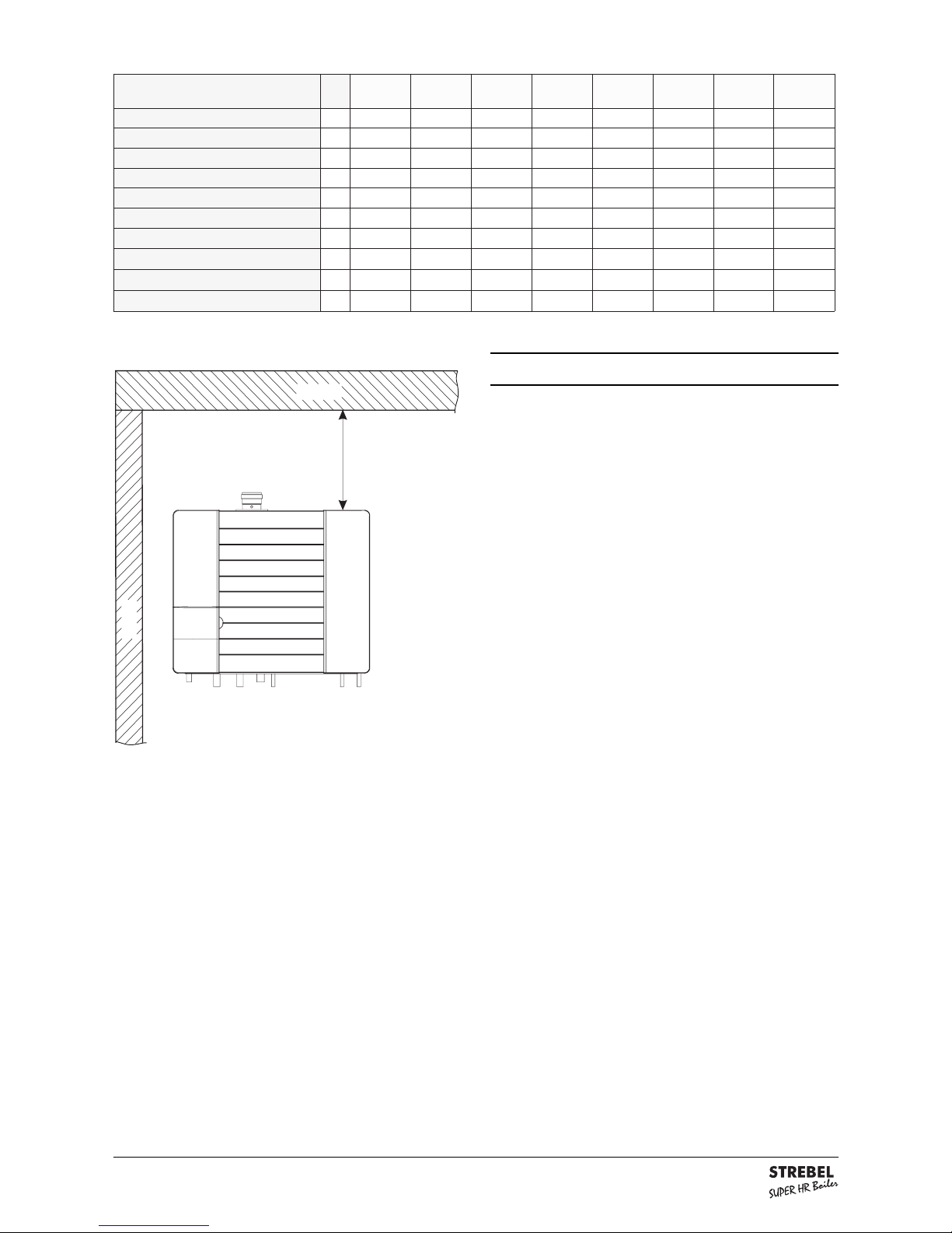
3 Mounting of the unit
The unit can be mounted practically to every wall with
the mounting bracket and the included fixingequipment.
The wall must be flat and of sufficient strength in order
to be able to carry the unit weight.
Above the unit there must be at least 250 mm working
space in order to be able to fit a twin supply and exhaust
system or 500mm when fitting a horizontal coaxial flue
system. On the left side of the unit at least 50 mm and
on the right side 10 mm must be reserved in connection
with fitting or removing of the casing. The location of the
unit can be determined by using the template on the
inside of the wrapper.
Installation instructions S-HR series page 5
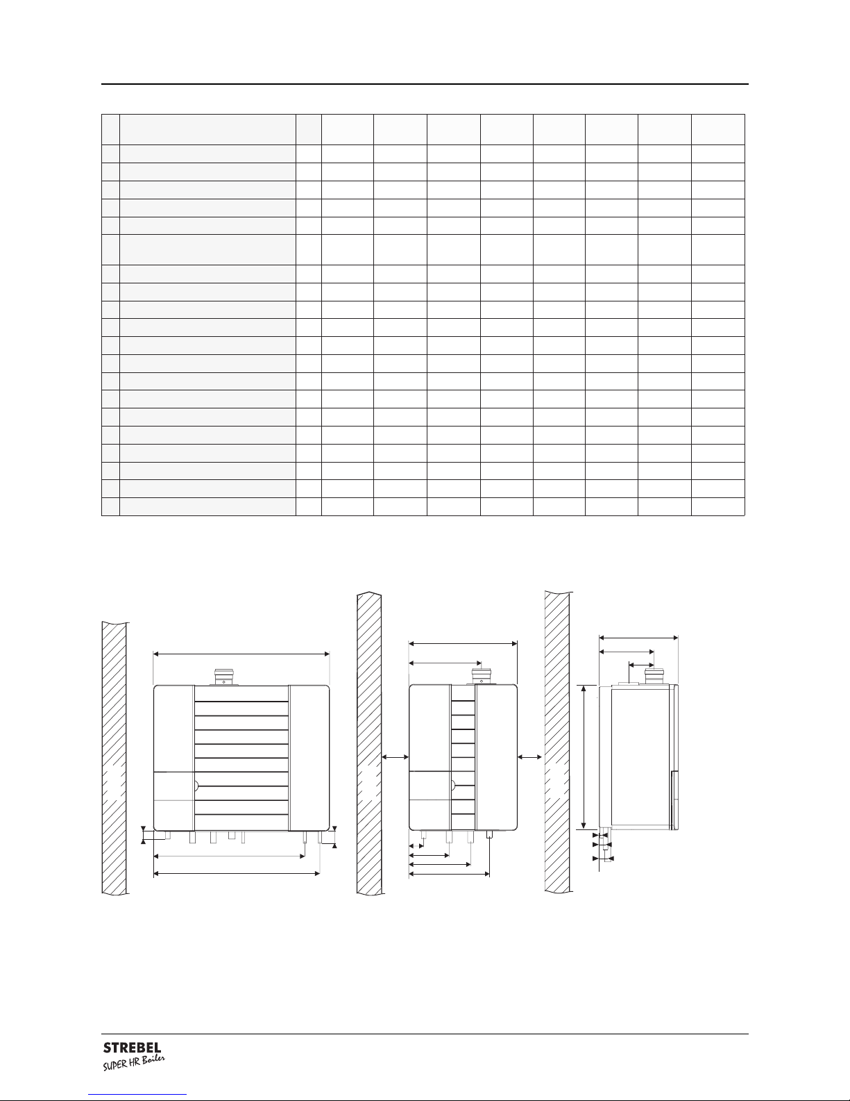
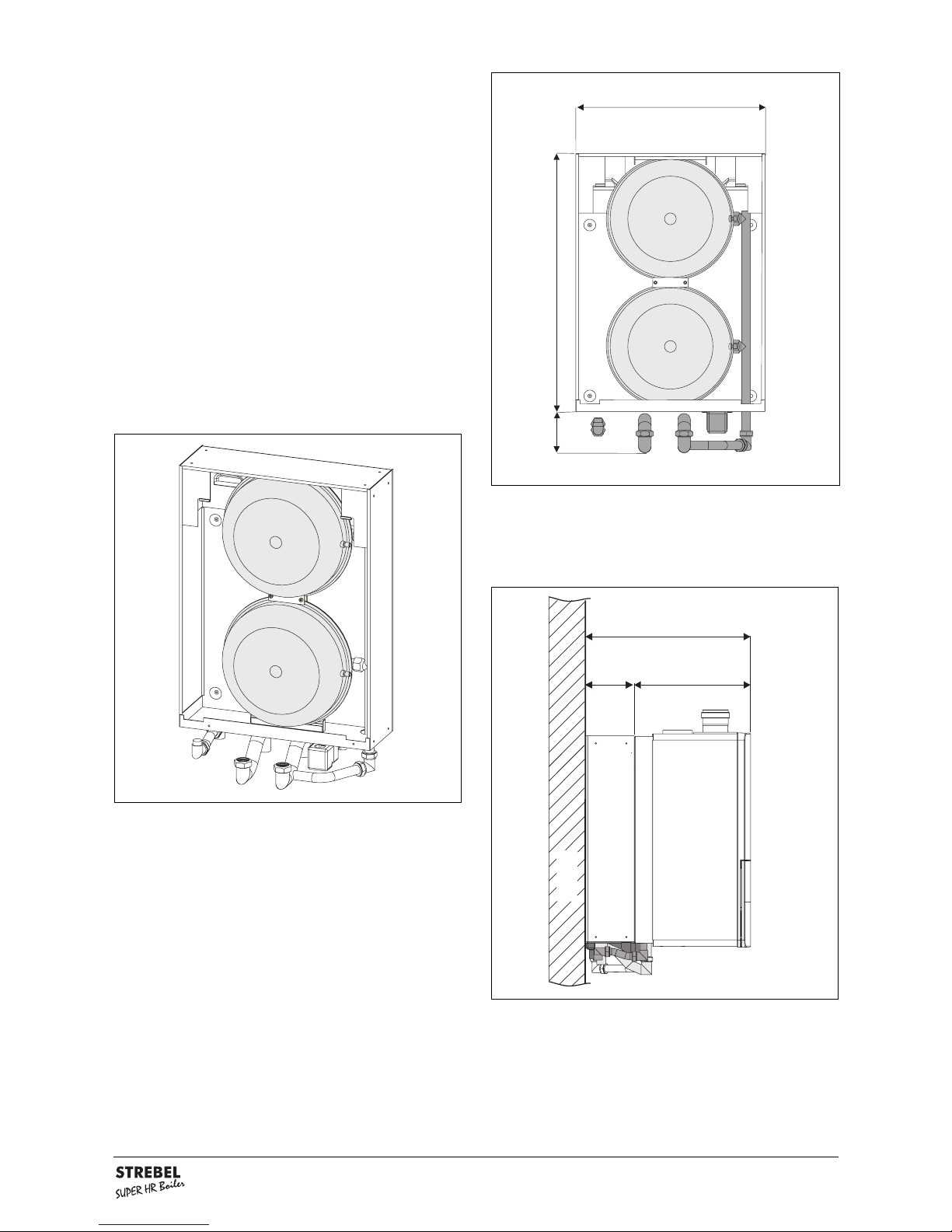
3.1 Dimensions
Dimensions (in mm) figure 1
wall
C
E
F
A
U
T
S
wall
B
M
N
P
Q
R
B
wall
D
H
J
K
1050
G
Dimensions table 1
tinufoepyt
RH-S
51
RH-S
42
RH-S
T42
RH-S
53
RH-S
T53
RH-S
15
RH-S
T15
RH-S
06
A thgieh
mm086086086086086086086086
B htdiw
mm0050050480050480660001066
C htped
mm073073073073073073073073
D tsuahxesageulf/edistfel
mm533533533533533594594594
E
tsuahxesageulf/ertnecotertnec
ylppusdna
mm021021021021021021021021
F tsuahxesageulf/kcab
mm072072072072072072072072
G epipsag/edistfel
mm5656565656565656
H epipwolf/edistfel
mm581581581581581581581581
J epipnruter/edistfel
mm582582582582582544544544
K epipnoitasnednoc/edistfel
mm073073073073073035035035
L epipknatnoisnapxe/edistfel
mm034034095
M epipretawdloc/edistfel
mm527527588
N epipretawtoh/edistfel
mm597597559
P *gfothgnelepip
mm8181818181818181
Q *kdnacfothgnelepip
mm0404040404040404
R *wdnae;r;afothgnelepip
mm0606060606060606
S *cepipfoertnec/kcab
mm5252525252525252
T *gepipfoertnec/kcab
mm0404040404040404
U *w;k;e;r;aepipfoertnec/kcab
mm0505050505050505
Installation instructions S-HR series page 6
4 Connecting the unit
The unit has the following connection pipes;
- The central heating pipes, hot and cold water pipes
can be connected to the installation by means of
compression fittings;
- The gas pipe of the unit is provided with a female
thread into which the tail piece of the gas valve can
be screwed;
- The condensation discharge pipe consist of an oval
24 mm plastic pipe. The discharge pipe can be connected to this by means of an open connection. If the
open connection is fitted in a different location, then
the pipe can be lengthened by means of a 32 mm
PVC sleeve;
- The flue gas exhaust system and air supply system
consist of 2 x 80 mm connections.
connection diameters table 2
unit pipes bottom figure 2
G A R C E K W
ceiling
wall
minimum
250 mm or
500 mm
tinufoepyt
RH-S
51
RH-S
42
RH-S
T42
RH-S
53
RH-S
T53
RH-S
15
RH-S
T15
RH-S
06
ylppusrianoitsubmoc
mm0808080808080808
tsuahxesageulf
mm0808080808080808
G-epipsag
edisni"½edisni"½edisni"½edisni"½edisni"½edisni"¾edisni"¾edisni"¾
A-epipwolfgnitaehlartnec
mm8282828282535353
R-epipnrutergnitaehlartnec
mm8282828282535353
C-epipegrahcsidnoitasnednoc
mm4242424242424242
E-epiplessevnoisnapxe
mm222222
K-epipretawdloc
mm515151
W-epipretawtoh
mm515151
Installation instructions S-HR series page 7
4.1 Central heating system
The unit pipes can be connected to the installation by
means of compression fittings. Reducers should be
used for connecting to thick-walled pipe (welded or
threaded).
When removing the plastic sealing caps from the pipes,
contaminated testing water can be released.
The unit has a self-adjusting and self-protecting control
system for the load and the pump capacity. By this means
the temperature difference between the supply and return
water is checked. The circulation pump will be able to
supply the given water displacement with an installation
resistance of up to 20 kPa, for this see table 3.
If an unacceptable temperature is detected, then the
control will repeatedly try to achieve water flow, and if
this does not work then the unit will switch off.
The S-HR 60 unit has a circulation pump which has a
residual suction head for the installation of 12 kPa. This
means that the unit can function normally in installations
which have an installation resistance of up to 12 kPa and
in cascade installations.
If the installation resistance is higher than 12 kPa, the
unit will automatically reduce in power.
If the capacity of the unit pump is insufficient, an extra
external pump can be installed in series with the unit.
The electrical side of this external circulation pump can
be connected in the Control Tower, by which means this
pump switches at the same times as the unit pump.
The maximum absorbed current consumption of the
external circulation pump may be 230 W (1 Amp).
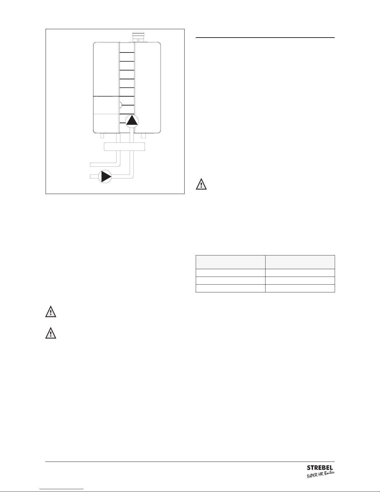
Use with a low velocity header can also be selected. In
this case a larger secondary sided water output has to
be taken into account, in order to affect the height of the
water temperature.
If the installation resistance is higher than the stated
value the pump will rotate at maximum pump capacity
and the load will be adjusted until an acceptable
temperature difference between supply and return water has been obtained. If, after this, the temperature
difference remains too much then the unit will switch
itself off and wait until an acceptable temperature has
arisen.
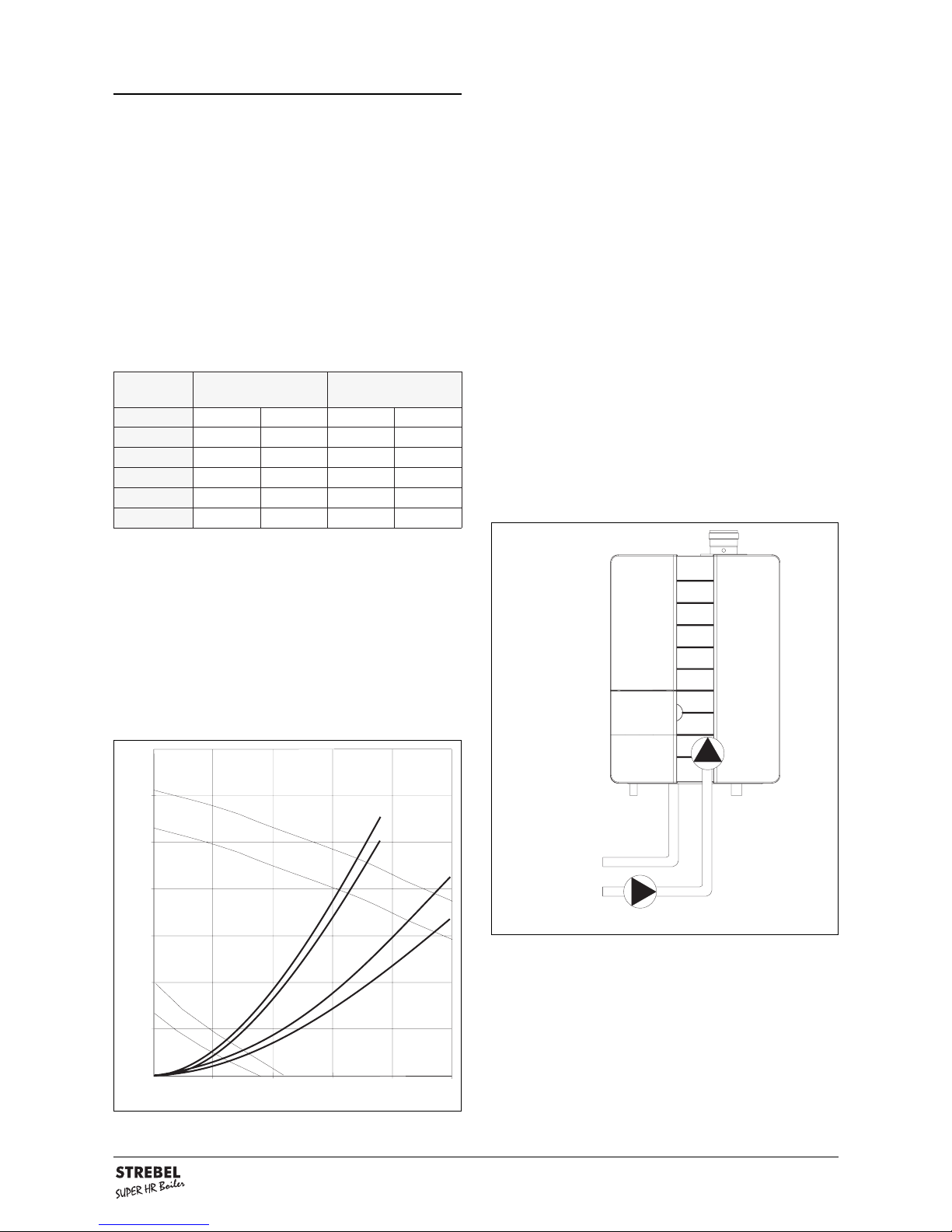
available water flow at full load table 3
external installation pump in series figure 3
tinufoepyt etarwolfretaw
D C°02T
elbissimrep
ecnatsisernoitallatsni
nim/lh/laPkrabm
51RH-S
9.900653053
T42/42RH-S
1,5108952052
T53/53RH-S
1,22423102002
T15/15RH-S
1,23929102002
06RH-S
9,73172221021
pump index lines graph 1
0 0,5 1 1,5 2 2,5
Q(m³/h)
7
6
5
4
3
2
1
0
H(m)
min (25%)
max (100%)
pump index line ARS 25-75
S-HR 15/24/35
S-HR 24T/35T
S-HR 51T
S-HR 51/60
pump index line ARS 25-70
Installation instructions S-HR series page 8
As standard the unit is provided with a water filter in the
return pipe of the unit. With this, possible contamination
of the central heating water is prevented from ending up
in the unit. The unit is also provided with an internal
safety valve set at 3 bar. This is connected to the
discharge construction to the waste together with the
condensation discharge.
If all, or a large part of the radiators are provided with
thermostatic radiator valves it is advisable to use a
pressure difference control (by pass) in order to prevent
flow problems in the installation.
The unit is designed to be used on sealed
system only.
Additives in the installation water are only
permitted in consultation with STREBEL
LTD.
When using more than one unit in an installation please
refer to the cascade installation instructions.
4.2 Expansion tank
All STREBEL S-HR-T units are provided with an
expansion tank on top of the calorifier. This expansion
tank is connected to the three-way valve and the
circulation pump. By this means the expansion water,
when functioning for the hot water supply, is prevented
from being shut off from the expansion tank when the
radiator thermostat valves are fully closed. A second
expansion tank in the installation is not a problem.
The STREBEL S-HR units are not equipped with an
expansion tank pipe. If a S-HR unit is combined with an
Comfort calorifier, the expansion tank connection is
included in the internal piping of the Comfort calorifier,
to which the expansion tank can be connected. If a
different calorifier is used then one has to take into
account that the expansion tank should be connected
between the three-way valve and the unit circulation
pump.
In connection with correct functioning of the
unit it is necessary for the expansion tank to
be connected to the expansion tank pipe of
the unit.
The expansion tank which is used should be geared to
the water content of the installation. The pre-pressure
depends on the installation height above the mounted
expansion tank.
external installation pump with low velocity header figure 4
choice of expansion tank table 4
evobathgiehnoitallatsni
lessevnoisnapxeeht
ehtfoerusserp-erp
lessevnoisnapxe
m5rab5,0
m01rab0,1
m51rab5,1
Installation instructions S-HR series page 9
The STREBEL S-HR24 and S-HR35 units can be
provided with an expansion tank module. By this means
the external expansion tank is cancelled. This
expansion tank module is placed behind the S-HR unit,
by which means the expansion tank is not noticeable. If
the S-HR unit is provided with a STREBEL Comfort
calorifier the overall depth will be equal. The content of
the two expansion tanks is 20 litres. The pre-pressure is
1 bar.
The expansion tank module can be supplied with the
necessary pipes to connect with the S-HR unit. The
connecting pipes for the installation correspond with
those of the unit and have the same centre-to-centre
distance to the wall. When checking the expansion
tanks these are accessible via the left, right and upper
sides. From these sides the tanks are also removable
and the unit does not have to be dismantled.
The space which is required for mounting the expansion
tank module corresponds with the required space for
mounting a S-HR unit. The included template and
mounting strip for the S-HR unit can be used for the
expansion tank module. The S-HR unit is fitted on to this
after the expansion tank module has been mounted.
The necessary mounting strip for the unit is present on
the module.
expansion tank module figure 5
side view of the module with S-HR unit figure 7
(dimensions in mm)
515
wall
145
370
front view of the expansion tank module figure 6
(dimensions in mm)
480
660105
Article numbers:
- the expansion tank module without pipe connections AEMO209U
- pipe connections for expansion tank module ALE0004U
Installation instructions S-HR series page 10
4.3 Underfloor heating systems
When connecting or using an underfloor heating system
fitted with plastic pipes one has to take into account that
the plastic pipes used meet the DIN 4726/4729
standard. It is stated in this standard that the pipes may
not have a higher oxygen transmittance than 0.1 g/m³.d
at 40°C. If the system does not meet this DIN standard,
then the underfloor heating section will have to be
separated from the central heating unit by means of a
plate heat exchanger.
In case of non-compliance with the
regulations concerning plastic underfloor
heating pipes, no claims can be made against
the guarantee conditions.
4.4 Gas pipe
The unit pipe is equipped with a female thread, into
which the tail piece of the gas valve can be screwed.
The Gas Safety (Installation and Use) Regulations
1994:
It is the law that all gas appliances are installed by
CORGI registered contractors in accordance with the
above regulations. Failure to install appliances correctly
could lead to prosecution. It is in your own interest, and
that of safety, to ensure that the law is complied with.
For good operation of the unit it is necessary that the
pre-pressure of the unit is higher than 20 mbar.
Make sure that the gas pipe work does not
contain dirt, particularly with new pipes.
4.5 Hot water supply (S-HR-T)
The unit pipes can be connected to the installation by
means of compression fittings. The unit is provided with
an inlet combination and safety valve set at 8 bar.
Together with the condensation discharge and the
discharge of the central heating safety valve (3 bar) this
is connected to one waste connection pipe.
A flow regulation valve is fitted in the cold water pipe.
The flow regulation valve provides that a quantity of
water is supplied which has a guaranteed outlet
temperature of 60°C (assuming a cold water
temperature of 10°C). The quantity of water is virtually
unaffected by the water pressure. With a water pressure
lower than 1.5 bar it is advisable to remove the inside
mechanism of the flow regulation valve. Connecting of
the drinking water installation should be done according
to the water BYE-laws.
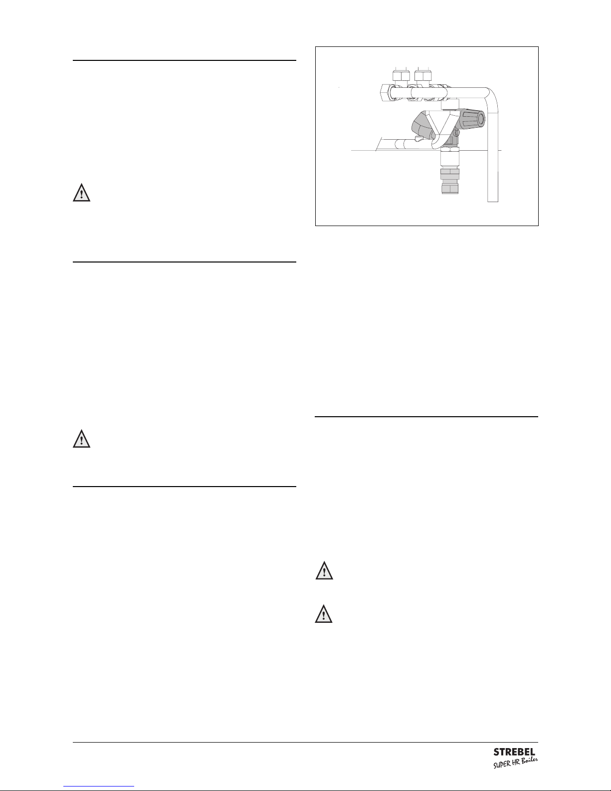
4.6 Condensation discharge pipe
The collective condensation discharge pipe should be
connected to the waste by means of an open
connection. By this means the possibility of sewer
gases ending up in the unit is prevented. The waste
connection should have a minimum diameter of 25 mm.
The following components are connected to the
collective condensation discharge pipe:
- Condensation discharge;
- Safety valves;
- Inlet combination (S-HR-T)
Discharging of the condensation water to the
precipitation discharge is not permitted in
view of the danger of it freezing.
Before putting the unit into operation fill the
trap with 300 ml of water.
inlet combination and safety valve figure 8
 Loading...