

Strebel S-HQ, SHQ25s, SHQ38s, SHQ51s, SHQ60s Installation Instructions Manual
...
Installation Instructions Strebel Q-boiler range
2
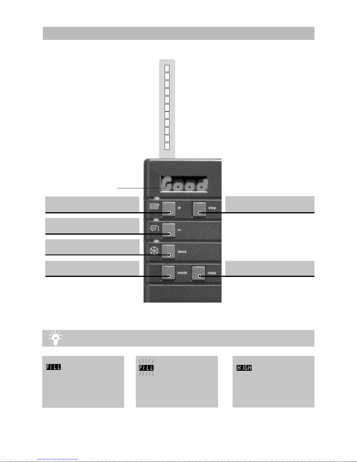
Central heating on / off
Domestic hot water (DHW) on / off
Pump programme on / off
Reset key Unlocking the boiler
in case of error
Step key Selecting chapters
display
Explanations of symbols and signs on the Control Tower display.
1
2
No heat requirement
Ventilation phase
Ignition phase
Burner active on central heating
Burner active on hot water
Fan check
Burner off when room thermostat is demanding
Pump overrun phase for central heating
Pump overrun phase for hot water
Burner off because of to high flow water temperature
Automatic venting programme
3
4
5
6
7
8
9
A
Water pressure is to low (<1,0 bar),
flashing FILL will alternate with indication
of water pressure, boiler power of 50% is
possible. The installation needs to be
topped up.
Operation indication
(in the first display position by technical read out)
Mode key Selecting chapters
Water pressure is to high (>2,8 bar), if
HIGH indication remains continuously
visible, the boiler is taken out of operation.
The installation pressure needs to be
decreased by draining water.
Water pressure is to low (<0,7 bar), FILL
indication remains continuously visible,
the boiler is taken out of operation. The
installation needs to be topped up.
0
From Good-read out to Technical read out (and vice versa):
- Press 5 sec. on the STEP key.

Installation Instructions Strebel Q-boiler range
3
Content
Declaration of conformity ............................................................................................................. 3
1 Introduction .................................................................................................................................. 4
2 Regulations .................................................................................................................................. 4
3 Scope of the supply...................................................................................................................... 6
4 Description of the boiler ............................................................................................................... 6
5 Mounting the boiler....................................................................................................................... 6
5.1 Dimensions ....................................................................................................................... 7
6 Connecting the boiler ................................................................................................................... 9
6.1 Central heating system ..................................................................................................... 9
6.2 Expansion vessel ............................................................................................................ 11
6.2.1 Expansion vessel module ............................................................................................... 12
6.3 Underfloor heating system (plastic pipes) ....................................................................... 13
6.4 Gas connection ...............................................................................................................13
6.5 Hot water supply .............................................................................................................13
6.6 Condensation drain pipe ................................................................................................. 14
6.7 Flue gas exhaust system and air supply system............................................................. 15
6.7.1 Dimensions of the flue gas and air intake duct................................................................ 18
7 External hot water cylinders ....................................................................................................... 19
8 Electrical connection .................................................................................................................. 20
9 Boiler controls ............................................................................................................................ 22
9.1 Explanation of the function keys ..................................................................................... 23
10 Filling and venting the boiler and installation.............................................................................. 24
10.1 Hot water supply ............................................................................................................. 24
11 Commissioning the boiler........................................................................................................... 25
11.1 Central heating system ................................................................................................... 25
11.2 Hot water supply ............................................................................................................. 25
11.3 Adjustments .................................................................................................................... 26
11.4 Activating factory settings (green key function)............................................................... 28
12 Isolating the boiler ..................................................................................................................... 29
13 Commissioning........................................................................................................................... 29
13.1 Checking for contamination............................................................................................. 29
13.2 Checking of the zero pressure control ............................................................................ 30
13.3 Checking the CO2............................................................................................................ 31
14 Maintenance............................................................................................................................... 32
14.1 Frequency of maintenance.............................................................................................. 32
14.2 Maintenance activities..................................................................................................... 33
14.3 Warranty ......................................................................................................................... 33
15 Technical specifications ............................................................................................................. 34
16 Parts of the boiler ....................................................................................................................... 35
17 Installation examples.................................................................................................................. 36
17.1 Radiator installation without thermostatic radiator valves................................................ 36
17.2 Radiator installation with underfloor heating zone........................................................... 37
18 Error indication ........................................................................................................................... 38
19 Declaration of conformity ........................................................................................................... 39
The appliance should only be installed by a Competent Gas Installer.
Work on the boiler must be carried out by a competent person, (Ref: Gas
Safety Installation and Use ) using correctly calibrated instruments with
current test certification.
Installation Instructions Strebel Q-boiler range
4
1 Introduction
These instructions describe the functioning, installation, use and primary maintenance
of STREBEL central heating units for the United Kingdom and Ireland. Where necessary
the different regulations for each country are separately described.
These instructions are intended for the use by Corgi registered installers or registered
Bord Gais installers in connection with the installation and putting into operation of
STREBEL units. It is advisable to read these instructions thoroughly, well in advance of
installation. Separate instructions for use are supplied with the unit for users of STREBEL
central heating units. STREBEL is not liable for the consequences of mistakes or
shortcomings which have found their way into the installation instructions or user’s
manual. Further, STREBEL reserves the right to alter its products without prior
notification.
When delivering the unit, give the customer clear instructions concerning its
use; present the customer with the user’s manual and card.
Each unit is fitted with an identification plate. Consult the details on this plate to verify
whether the unit is compliant with its intended location, e.g.: gas type, power source
and exhaust classification.
Relevant Installation, Service and User manuals:
- BrainQ Digital room thermostat
- MadQ Cascade-/Zone controller
2 Regulations
The following regulations apply to installation of STREBEL central heating units:
Legislation and Regulations.
Gas Safety (Installation and Use). All gas appliances must by law, be installed by a
competent person, eg. Members of CORGI and in accordance with the current Gas Safety
Regulation. Failure to install appliance correctly could lead to prosecution.
In addition to the above regulations this appliance must be installed in compliance with the
current IEE Regulations, the Building Standards (Scotland Consolidation) Regulations.
Regulations and bye laws of the Local Water Authority and the Current Health and Safety
Regulation.
The current, Electricity at Work Regulation must be complied with and also be in
accordance with the relevant and current editions of the British Standards.
The STREBEL S-HQ boiler is a certified appliance and must not be modified or installed
in any way contrary to this Installation Manual.
Manufacturers instructions must not be taken in any way as overriding statutory
obligations.
Installation Instructions Strebel Q-boiler range
5
The STREBEL S-HQ is a central heating unit with an optional integrated hot water
function. These units must be connected according to these instructions and all
installation norms in respect of the part of the unit to be connected.
Observe the following rules of safety:
- All work on the unit must take place in a dry environment.
- STREBEL units may never be in operation without their housing, except in
connection with maintenance or adjustments (see Chapter 13 and 14).
- Never allow electrical or electronic components to come into contact with water.
Carry out the following tasks in connection with maintenance, etc. to an already-
installed unit:
- Shut down all programmes
- Close the gas tap
- Remove the plug from the wall socket
- Close the stop cock of the unit’s intake connection
Take note of the following when maintenance or adjustments are needed:
- The unit must be able to function during these activities; for this reason, the unit’s
supply voltage, gas pressure and water pressure must be maintained. Ensure that
these is not a source of potential danger during these activities.
Following maintenance or other activities; always check the installation of all
parts through which gas flows (using leak-search spray).
Following maintenance or other activities, always replace the housing and
secure it with the screw behind the door at the front of the casing.
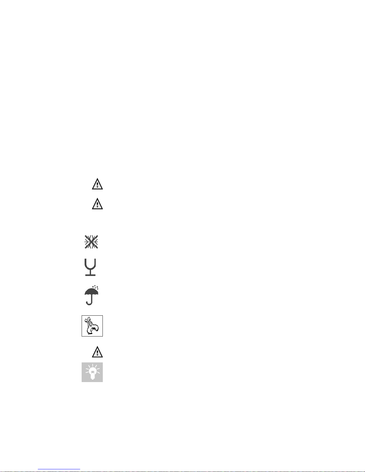
The following (safety) symbols may be encountered in these installation instructions
and on the unit:
This symbol indicates that the unit must be stored away from frost.
This symbol indicates that the packaging and/or contents can be damaged as
a result of insufficient care taken during transport.
This symbol indicates that, whilst still in its packaging, the unit must be
protected from weather conditions during transport and storage.
KEY-symbol. This symbol indicates that assembly or dismantling, must be
carried out.
ATTENTION symbol. This symbol indicates that extra attention must be paid
in connection with a particular operation.
Useful tip or advice

Installation Instructions Strebel Q-boiler range
6
3 Scope of the supply
The boiler is supplied ready for use. The supply kit is composed as follows:
• Boiler with casing; • Template on the package wrapper;
• Automatic vent (inside the boiler); • Installation instructions
• Safety valve (inside the boiler); • Operating manual;
• Suspension bracket • Warranty card;
• Draining valve with T-piece; • Benchmark logbook.
• Fixing material consisting of plugs and
screws;
4 Description of the boiler
The STREBEL S-HQ boiler is a room sealed, condensing and modulating central heating
boiler, with or without an integrated hot water facility.
The boiler is provided with a compact stainless steel heat exchanger with smooth
tubes. A well thought out principal using durable materials.
The boiler burns gas for supplying warmth. The heat is transferred in the heat
exchanger to the water in the central heating system. By cooling down the flue gasses
condensate is formed. This results in high efficiency. The condensate, which has no
effect on the heat exchanger and the function of the boiler, is drained through an
internal siphon.
The boiler is provided with an intelligent control system (CMS Control Management
System). The boiler anticipates the heat demand of the central heating system or the
hot water facility.
When an outside sensor is connected to the boiler works weather dependantly. This
means that the boiler control measures the outside temperature and flow temperature.
With this data the boiler calculates the optimal flow temperature for the installation.
Explanation of the type indication: STREBEL Q 51C
Q = Type
51 = Nominal load in kW
C = Combi (S = Solo)
Room sealed boiler
The boiler retreives its
combustion air from
outside then discharges
the flue gasses to the
outside.
Condensing
Retrieves heat from the
flue gasses. Water
condensates on the
heat exchanger.
Modulating
Higher or lower burning
according to the heat
demand.
Stainless Steel
Super solid kind of
steel which keeps its
quality for life. It will not
rust or erode in contrast to composition
materials, like aluminium.

Installation Instructions Strebel Q-boiler range
7
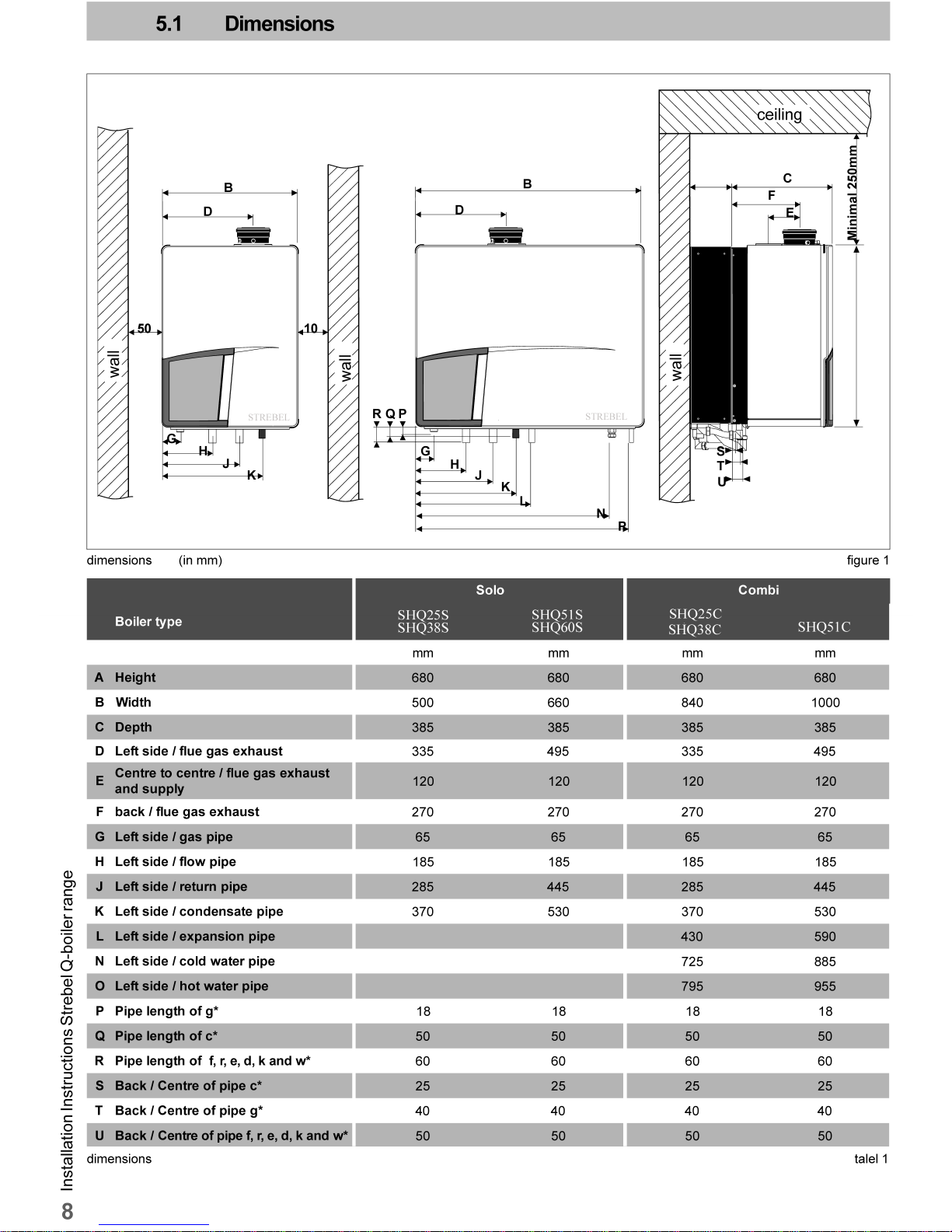
5 Mounting the boiler
The room where the boiler will be placed must always be frost free.
It is NOT necessary to have a purpose provided air vent in the room or internal space in
which the boiler is installed. Neither is it necessary to ventilate a cupboard or
compartment in which the boiler is installed, due to the extremely low surface
temperature of the boiler casing during operation. Therefore the requirements of BS 6798,
Clause 12, and BS5440:2 may be disregarded.
The boiler can be mounted practically to any wall with the suspension bracket and the
enclosed fixing equipment. The wall must be flat and of sufficient strength in order to be able
to carry the boiler weight with its water content.
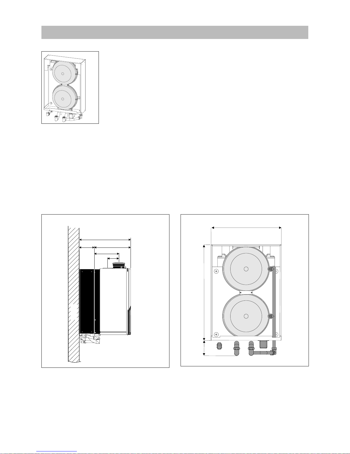
Above the boiler there must be at least 250 mm working space in order to be able to fit
a coaxial flue system or a twin supply. On the left side of the boiler at least 50 mm and
on the right side 10 mm must be reserved to allow fitting or removing of casing. The
location of the boiler can be determined by using the template located inside the boiler
packaging.
Lift the boiler only by the boilers rear wall
Installation Instructions Strebel Q-boiler range
10
6 Connecting the boiler
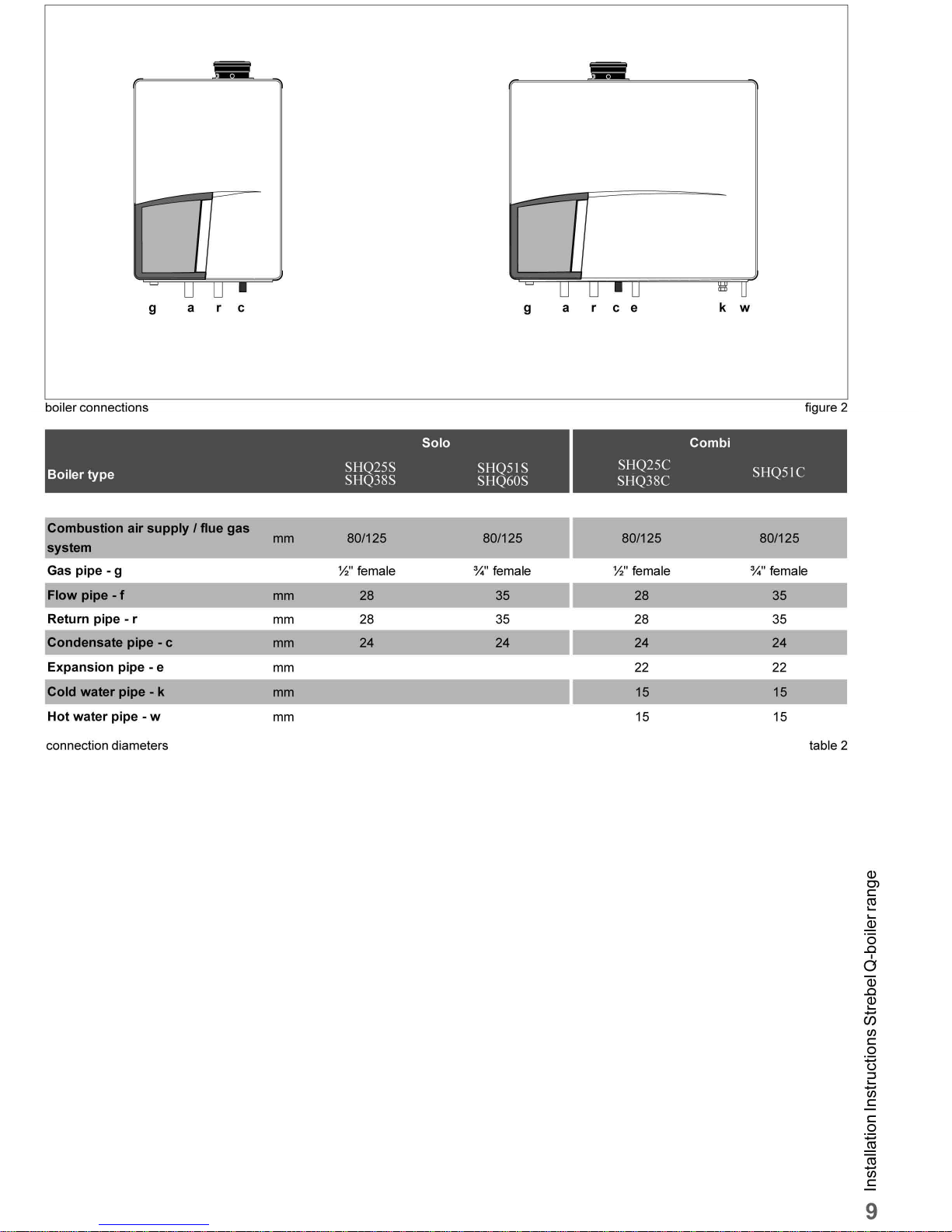
The boiler has the following connection pipes;
- The central heating pipes.
These can be connected to the installation by means of compression fittings;
- The gas pipe.
It is provided with a female thread into which the tail piece of the gas valve can be
screwed;
- The condensation drain pipe.
It consists of an oval 24 mm plastic pipe. The drain pipe can be connected to this
by means of an open connection. If the open connection is fitted in a different
location, then the pipe can be lengthened by means of a 32 mm PVC sleeve;
- The flue gas exhaust system and air supply system.
It consists of a concentric connection 80/125 mm.
- Cold and hot water pipes.
Only Combi boilers: These consist of 15 mm copper pipe and can be connected
to the installation by means of compression fittings.
It is recommended that isolation valves are fitted to all heating and hot water
connections to facilitate ease of future maintenace.
It is advisable to spray-clean all of the unit’s connecting pipes and/or to
spray-clean/blow-clean the installation before connecting it to the unit.
6.1 Central heating system
Connect the central heating system according to the actual regulations.
The boiler pipes can be connected to the installation by means of compression fittings.
Reducers should be used for connecting to thick-walled pipe (welded or threaded).
When removing the plastic sealing caps from the pipes, contaminated testing
water can be released.
The boiler has a self-adjusting and self-protecting control system for the load and the pump
capacity. By this means the temperature difference between the flow and return water is
checked. Table 3 shows the water displacement which supplies th e circulation pump at
certain installation resistance.
A low velocity header must be connected to the Q51C, Q51S and Q60S to
prevent flow problems over the boiler.
STREBEL supplies the AA1OV09U Low velocity header for 1 boiler. This can be
connected directly under the boiler on the flow and return pipe.
Boiler type pump type water flow rate permissible installation
resistance
UPER l/min l/h kPa mbar
Combi
Q25C
20-60 16,2 972 29 290
Q38C
20-70 24,6 1478 20 200
Q51C
20-70 30,1 1803
Solo
Q25S
20-60 9,7 583 47 470
Q25S
20-60 1 6,2 972 32 320
Q38S
20-70 24,6 1478 22 220
Q51S
20-7030,11803
Q60S
20-70 38,9 2333
Installation resistance table 3


Installation Instructions Strebel Q-boiler range
12
6.2 Expansion vessel
The central heating system must be provided with an expansion vessel. The expansion
vessel which is used should be geared to the water content of the installation. The precharge pressure depends on the installation height above the mounted expansion vessel.
See table 4.
All Combi boilers are provided with an expansion vessel connection. This pipe is
connected with the three way valve and boiler pump. This prevent the expanding water,
during hot water production, is being closed off from the expansion vessel, when the
thermostatic radiator valves are fully closed. A second expansion vessel in the installation
is not a problem.
In connection with correct functioning of the boiler it is necessary for the
expansion vessel to be connected to the expansion vessel pipe of the boiler.
The Solo boilers are not provided with an expansion vessel connection. When one of
these Solo boilers is combined with a cylinder then one has to take into account that the
expansion vessel should be connected between the three-way valve and the boiler
circulation pump.
choice of expansion vessel table 4
insta lla tio n height a bove
the expansion vessel
pre-charge pressure
of the expansion vessel
5 m 0,5 bar
10 m 1,0 bar
15 m 1,5 bar
Installation Instructions Strebel Q-boiler range
13
side view of the module with boiler (dimensions in mm) figure 5
540
wall
155
385
front view of the module with boiler (dimensions in mm) figure 6
660
105
6.2 Expansion vessel module
The STREBEL Q25S and Q38S boilers can be provided with an expansion vessel
module. By this means the external expansion vessel is not required. This expansion
vessel module is placed behind the STREBEL S-HQ boiler, by which means the
expansion vessel is not noticeable. The content of the two expansion vessels is 20 litres.
The pre-charge pressure is 1 bar.
The expansion vessel module can be supplied with the necessary pipes to connect with
the STREBEL S-HQ boiler. The connecting pipes for the installation correspond with
those of the boiler and have the same centre-to-centre distance to the wall.
When checking the expansion vessels these are accessible via the left, right and upper
sides. From these sides the tanks are also removable and the boiler does not have to
be dismantled.
The space which is required for mounting the expansion vessel module corresponds
with the required space for mounting an STREBEL S-HQ boiler. They included template
and mounting strip for the boiler which can be used for the expansion vessel module.
The boiler is fitted on to this after the expansion vessel module has been mounted. The
necessary mounting strip for the boiler is present on the module.
Article numbers:
- the expansion vessel module without pipe connections AEM0209U
- pipe connections for expansion vessel module ALE0004U
480
expansion vessel module
figure 4
 Loading...