

Strebel S-FX Series, S-FX 70, S-FX 125, S-FX 220, S-FX 320 Installation Operating & Maintenance Manual
STREBEL
S-FX Boiler Range
Models 70 – 125 – 220 - 320
Floor Standing High Efficiency Condensing Boiler
Installation, Operating & Maintenance Manual
Please read and understand before commencing installation and leave the manual with the customer for future reference.
2019-07-01 v1


3
TABLE OF CONTENTS
1 INTRODUCTION .................................................................................................................................. 6
2 SAFETY GUIDELINES ......................................................................................................................... 6
3 TECHNICAL DATA for S-FX BOILERS .............................................................................................. 8
3.1 FUNCTIONAL INTRODUCTION ...................................................................................................... 8
3.1.1 Technical specifications datasheet ............................................................................... 9
3.2 ERP SPECIFICATIONS DATASHEET ........................................................................................... 10
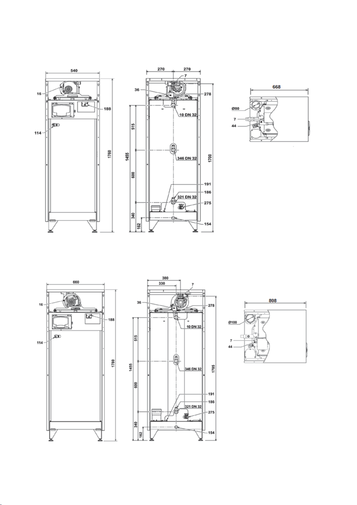
4 BOILER DIMENSIONS ....................................................................................................................... 11
4.1 S-FX 70 ................................................................................................................................. 11
4.2 S-FX 125 ............................................................................................................................... 11
4.3 S-FX 220 ............................................................................................................................... 12
4.4 S-FX 320 ............................................................................................................................... 12
5 INSTALLATION OF THE S-FX BOILERS ......................................................................................... 13
5.1 GENERAL NOTES .................................................................................................................... 13
5.2 BOILER ROOM ......................................................................................................................... 13
5.2.1 General ....................................................................................................................... 13
5.2.2 Boiler room ................................................................................................................. 13
6 CONNECTIONS ................................................................................................................................. 14
6.1 BOILER CONNECTIONS ............................................................................................................. 14
6.2 GAS CONNECTION................................................................................................................... 15
6.3 FLOW & RETURN CONNECTIONS .............................................................................................. 16
6.4 WATER QUALITY ...................................................................................................................... 17
6.5 CHEMICAL WATER TREATMENT ................................................................................................. 17
6.6 CONDENSATE DRAIN ............................................................................................................... 17
6.7 EXPANSION VESSEL ................................................................................................................ 18
6.8 PRESSURE RELIEF VALVE......................................................................................................... 18
6.9 NON-RETURN FLAP. ............................................................................................................... 18
6.10 BYPASS .................................................................................................................................. 18
6.11 FROST PROTECTION ................................................................................................................ 18
6.12 AUTOMATIC FILLING SYSTEM / PRESSURISATION UNITS. ........................................................... 18
6.13 WATER PRESSURE .................................................................................................................. 18
6.14 INSTALLING A STRAINER AND/OR DIRT SEPARATOR .................................................................... 19
6.15 PLASTIC PIPING IN THE HEATING SYSTEM .................................................................................. 19
7 BOILER SHUNT PUMP ...................................................................................................................... 20
7.1 S-FX 70 & 125 HYDRAULIC GRAPH .......................................................................................... 20
7.2 S-FX 220 & 320 HYDRAULIC GRAPH ........................................................................................ 20
8 FLUE GAS AND AIR SUPPLY SYSTEM .......................................................................................... 21
8.1 GENERAL ................................................................................................................................ 21
8.2 S-FX EXHAUST FLUE CONNECTION ......................................................................................... 22
8.3 PLANTROOM COMBUSTION AIR ................................................................................................ 23
8.3.1 Air contamination ........................................................................................................ 23
8.4 BOILER CATEGORIES - TYPES OF FLUE GAS SYSTEMS. ............................................................... 24
8.5 FLUE TERMINAL ...................................................................................................................... 24
8.5.1 Horizontal Flue Terminal Positioning.......................................................................... 24
8.5.2 Vertical Flue Terminal Positioning .............................................................................. 24
8.5.3 Common Flue / Ducts ................................................................................................. 24
8.6 HORIZONTAL FLUE TERMINAL RISK ASSESSMENT ..................................................................... 25
8.6.1 Figure 12 – line G ....................................................................................................... 25
8.6.2 Figure 7 – line Y ......................................................................................................... 25
8.7 OTHER FLUE TERMINAL MINIMUM DISTANCES .......................................................................... 26
9 ELECTRICAL INSTALLATION .......................................................................................................... 27
9.1 GENERAL ................................................................................................................................ 27
9.2 CONNECTION MAINS SUPPLY .................................................................................................... 27
9.3 ELECTRICAL CONNECTIONS ..................................................................................................... 27
9.4 ELECTRICAL SCHEMATICS ....................................................................................................... 28
9.5 DRAWING NUMBER LEGEND .................................................................................................... 31
9.6 SCHEMATIC & WIRING EXAMPLES ............................................................................................ 32
9.6.1 2 x Direct heating circuits ........................................................................................... 32
9.6.2 1 x Direct heating circuit & 1 x dhw primary circuit with pump ................................... 32

4
9.6.3 1 x Direct heating circuit & 1 x dhw primary circuit with three way valve ................... 33
9.6.4 1 x Direct heating circuit & 1 x dhw primary circuit with pump (with phe) ................... 33
9.6.5 3 x S-FX in cascade: 1 x Direct heating circuit & 1 x dhw primary circuit with pump . 34
9.6.6 Remote on / off control, remote reset & bms outputs per S-FX boiler ........................ 35
10 BURNER CONTROLLER AND DISPLAY. ........................................................................................ 36
10.1 DISPLAY AND BUTTONS ............................................................................................................ 36
10.1.1 Display icons ............................................................................................................... 36
10.2 POWERING UP & DOWN ........................................................................................................... 37
10.2.1 Turning on the s-fx boiler for the first time .................................................................. 37
10.2.2 Changing the contrast ................................................................................................. 37
10.2.3 Turning off the boiler display ....................................................................................... 37
10.2.4 Powering down the complete boiler ............................................................................ 37
10.3 USER MENU STRUCTURE ......................................................................................................... 38
10.3.1 Heating Parameter ...................................................................................................... 39
10.3.2 DHW Parameter .......................................................................................................... 41
10.3.3 Time Programming ..................................................................................................... 41
10.3.4 Holiday Function ......................................................................................................... 42
10.3.5 Setting Date & Time .................................................................................................... 42
10.4 TECHNICAL MENU STRUCTURE ................................................................................................. 43
10.4.1 To Access the Parameters.......................................................................................... 43
10.4.2 To Access the Configuration, Transparent & System Parameters ............................. 43
10.4.3 Configuration Parameter - b........................................................................................ 44
10.4.4 Transparent Parameter – P ........................................................................................ 45
10.4.5 System Parameter – P. ............................................................................................... 46
10.4.6 S-FX Information Menu ............................................................................................... 47
11 S-FX CASCADING ............................................................................................................................. 48
11.1 SYSTEM SETUP ........................................................................................................................ 48
11.2 BOILER CASCADE COMMUNICATION SETUP. ............................................................................... 48
12 NATURAL GAS TO LPG CONVERSION .......................................................................................... 49
12.1 PART 1 – FITTING THE LPG CONVERSION KIT ........................................................................... 49
12.2 PART 2 – SOFTWARE CHANGE ................................................................................................. 49
13 COMMISSIONING THE BOILER........................................................................................................ 50
13.1 FIRST: FLUSHING THE BOILER WITH WATER .............................................................................. 50
13.2 SECOND: FILLING & VENTING THE BOILER AND THE SYSTEM ...................................................... 50
13.3 THIRD: CHECK THE WATER FLOW ............................................................................................. 50
13.4 MOUNTING CONDENSATE TRAP ................................................................................................ 50
13.5 CHECKING GAS PRESSURE ...................................................................................................... 50
14 ADJUSTING AND SETTING THE BOILER ....................................................................................... 51
14.1 INTRODUCTION ........................................................................................................................ 51
14.1.1 Combustion table ........................................................................................................ 51
14.1.2 Adjustment Values ...................................................................................................... 52
14.2 PUTTING THE BURNER INTO HIGH & LOW FIRE .......................................................................... 54
14.3 HIGH & LOW FIRE ADJUSTMENT ............................................................................................... 54
14.3.1 Adjusting The Burner At High Fire .............................................................................. 54
14.3.2 Adjusting The Burner At Low Fire ............................................................................... 54
14.3.3 Location Of Adjustment Screws .................................................................................. 55
14.4 HEATING CAPACITY ADJUSTMENT (RANGE RATED) ................................................................... 55
14.5 CASCADE TEST MODE ............................................................................................................. 56
14.6 START UP CHECKLIST .............................................................................................................. 57
15 INSPECTION, MAINTENANCE AND SERVICE. ............................................................................... 59
15.1 GENERAL ................................................................................................................................ 59
15.2 INSPECTION, MAINTENANCE AND SERVICE. ................................................................................ 59
15.3 MAINTENANCE CHECKLIST ....................................................................................................... 63
16 FAULT CODES / TROUBLESHOOTING ........................................................................................... 64
16.1 LIST OF FAULT CODES ............................................................................................................. 64
16.1.1 Lock Out Faults – A Codes (Requires Resetting) ....................................................... 64
16.1.2 Temporary Faults – F Codes (Automatically Reset) ................................................... 65
17 USER INSTRUCTIONS ...................................................................................................................... 66
18 USER’S PART. ................................................................................................................................... 66

5
18.1 SAFETY GUIDELINES. ............................................................................................................... 66
18.2 TO TURN OFF GAS TO THE APPLIANCE ....................................................................................... 66
18.3 MAINTENANCE AND INSPECTION ............................................................................................... 66
6
1 INTRODUCTION
This manual is written for:
▪ The Installer.
▪ System Design Engineer.
▪ The Service Engineer.
▪ The User.
Strebel Ltd are not accountable for any damage caused by incorrect following these instructions. For service and
repair purposes use only original Strebel Ltd spare parts.
All documentation produced by the manufacturer is subject to copyright law
2 SAFETY GUIDELINES
Carefully read all the instructions before commencing installation.
Keep these instructions near the boiler for quick reference.
The appliance should be installed by a skilled installer such as GAS SAFE registered person, electrical work
carried out by a qualified person, all according to national and regional standards.
Failure to comply with these regulations could deem the warranty invalid.
This appliance must be installed in accordance with the rules that apply and only be used in an adequately
ventilated space conforming to standards in place.
Without written approval of the manufacturer the internals of the boiler may not be changed. When changes are
executed without approval, the boiler certification becomes invalid.
Commissioning, maintenance and repair must be done by a skilled installer/engineer, according to all applicable
standards and regulations.
A. This appliance does not have a pilot. It is equipped with an ignition device which automatically lights the
burner. Do not try to light the burner by hand.”
B. BEFORE OPERATING smell all around the appliance area for gas. Be sure to smell next to the floor because
some gas is heavier than air and will settle on the floor.”
C. Do not use this appliance if any part has been under water. Immediately call a qualified service technician to
inspect the appliance and to replace any part of the control system and any gas control which has been
under water.”
What to do if you smell gas:
▪ Do not use any electrical equipment.
▪ Do not press any switches.
▪ Close the gas supply.
▪ Ventilate the room (open the windows and/or outdoor water heater room doors).
▪ Immediately warn the installer.
The manufacturer/supplier is not liable for any damage caused by inaccurately following of these
mounting instructions. Only original parts may be used when carrying out any repair or service
works.
This appliance can be used by children aged from 8 years and above and persons with reduced
physical, sensory or mental capabilities or lack of experience and knowledge if they have been given
supervision or instruction concerning use of the appliance in a safe way and understand the hazards
involved.
“WARNING: Improper installation, adjustment, alteration, service or maintenance can cause property
damage, personal injury (exposure to hazardous materials) * or loss of life. Installation and service must be
performed by a qualified installer, service agency or the gas supplier (who must read and follow the supplied
instructions before installing, servicing, or removing this water heater.

7
These instructions are written for the installer of Strebel products and contain all necessary information on
the installation and adjustment of S-FX ranges of boilers. Please read these instructions fully before
installation to ensure that all work is carried out correctly.
We suggest that you keep a copy of these instructions near the boiler.
These instructions together with those in any supplemental instruction booklet cover the basic principles
to ensure the satisfactory installation of the boiler, although detail may need slight modification to suit
particular local site conditions.
It is the law that all gas appliances and fittings are installed by a competent person (such as a Gas Safe
registered installer) and in accordance with The Gas Safety (installation and Use) Regulations.
The relevant British standards for installation, codes of practice or rules in force and in accordance with
the Manufactures’ instructions.
The installation must be carried out in accordance with the following regulations plus relevant codes &
standards:
- Due consideration must be given to current Health & Safety Legislation while this product is being
installed.
- Key Approved Documents to the Building Regulations, in the region of the United Kingdom that
this product is being installed.
- The Local Building Regulations and Local water by-laws, the gas services area and the Local
Authority recommendations.
- The appropriate British & European Standards for the type of installation and fuel used, including
but not exclusively the following standards: -
o BS 5440: Part 2 (Flues and Ventilation).
o BS 6644: Installation of gas-fired hot water boilers of rated inputs between 70kW & 1.8MW
- The clean air act as defined by the local authority.
- The appropriate documents as produced by the Institution of Gas Engineers and Managers
Documents (IGEM) for the type of installation and fuel used, including but not exclusively the
following documents: -
o IGE/UP/1.
o IGE/UP/2.
o IGE/UP/4.
o IGEM/UP/10 Edition 4.
- If the product is being fuelled with LPG then the appropriate UKLPG Codes of Practice (CoP)
should be referred to.
- Wiring to the appliance must be in accordance with the IEE (BS 7671) Wiring Regulations the
Health and Safety Document No 635 “The Electricity at Work Regulations 1989” and any local
regulations that apply.
- CP 342: Part 2, 1994. Code of practice for centralised hot water supply – buildings other than
individual dwellings.
- CIBSE, Guides A, B and C.
Adhere to all regulations that are in force at the time of installation or service.

8
3 TECHNICAL DATA FOR S-FX BOILERS
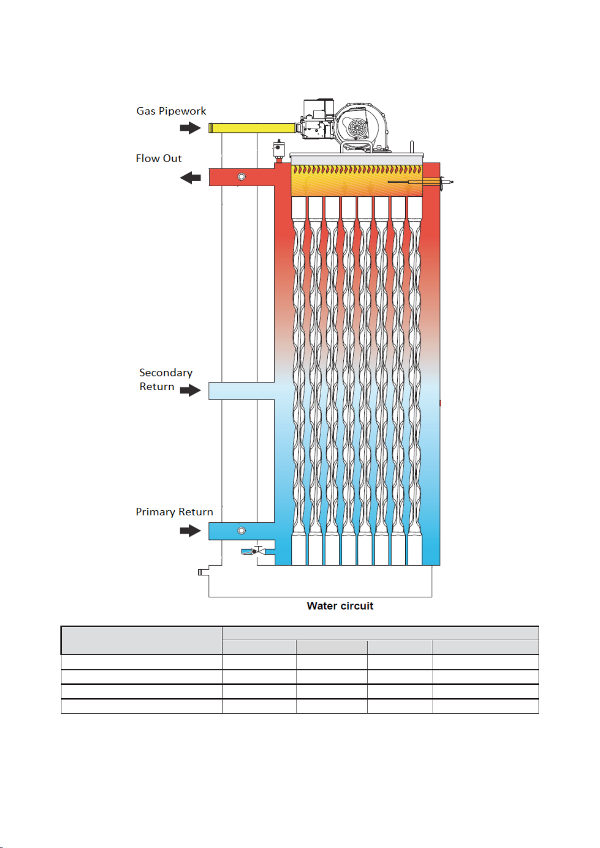
3.1 Functional introduction
The S-FX boilers is a high efficiency, low emissions premix condensing heat generator for heating, running on
natural gas or LPG and equipped with a microprocessor control system.
The boiler body consists of a patented stainless-steel helical tube heat exchanger and a premix burner in stainless
steel, equipped with electronic ignition with ionisation flame control, modulating fan and modulating gas valve.
The S-FX is a heat generator arranged to operate alone or in cascade.
The S-FX boiler is standard set for Natural Gas (G20).
Boiler control includes:
▪ Cascade control for up to six boilers.
▪ Remote operation and heat demand indication from each boiler.
▪ Weather compensation control.
▪ Calorifier control.
Connections for:
▪ On/Off thermostat.
▪ 0-10 VDC remote flow temperature (set point)
control.
▪ 0-10 VDC remote burner input control.
▪ Outdoor temperature sensor.
▪ External calorifier pump or diverter valve.
▪ Boiler pump.
▪ System pump.
▪ External flow switch or external safety device.
▪ External system sensor.
▪ DHW indirect sensor or DHW control thermostat.
Cascade control
When using the integrated cascade control, a maximum of six boilers can be controlled in a cascade
configuration. Using an appropriate external control, this number may be increased at will.
0-10 VDC connection available
The boiler flow temperature or power input can be controlled by an external 0-10 VDC signal. When a number of
boilers are cascaded, and controlled by the integrated cascade control, the signal should be directed to the master
boiler only. If an alternative control is used, more than one boiler may be controlled by a 0-10 VDC signal.
Time program
For both central heating and hot water function of the boiler, time programs with six programmable periods per day
are available. These time programs are set and activated by entering the desired settings directly at the boiler
control panel.
9
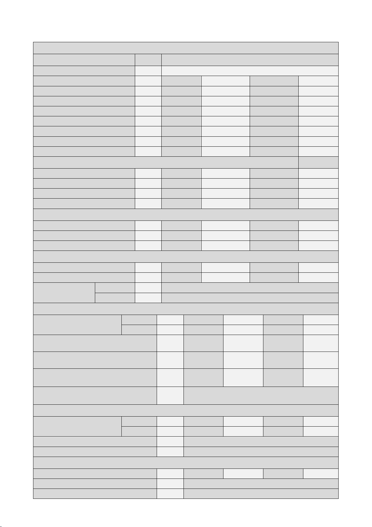
3.1.1 TECHNICAL SPECIFICATIONS DATASHEET
GENERAL
Product identification number:
CE 0085CL0441
Gas Appliance Type
B23
Boiler Model
S-FX 70
S-FX 125
S-FX 220
S-FX 320
Classification
II2H3P
II2H3P
II2H3P
II2H3P
Water Content
litre
166
265
386
530
Weight (empty)
kg
180
280
400
500
Flow Connection
inch / F
R 1 ¼”
R 1 ¼”
R 2”
DN65 PN16
Return Connections
inch / F
R 1 ¼”
R 1 ¼”
R 2”
DN65 PN16
Gas Connection
inch
R ¾”
R 1”
R 1”
R 1”
Flue Exhaust Connection
mm
80
100
160
200
HEATING Values min-max:
Nominal Input (net)
kW
14.0 - 65.5
23.0 - 116.0
41.0 - 207.0
62.0 - 299.0
Nominal Input (gross)
kW
15.5 - 72.7
25.5 - 128.7
45.5 - 229.7
68.8 - 331.8
Nominal Output 80/60 °C
kW
13.7 - 64.4
22.5 - 114.0
40.2 - 204.0
60.8 - 294.5
Nominal Output 50/30 °C
kW
15.0 - 69.9
24.8 - 125.0
44.2 - 220.0
66.8 - 320.0
BOILER EFFICIENCY
Efficiency – Full Load 100% NCV
%
98.20
97.80
98.30
98.40
Efficiency – Full Load 30% NCV
%
109.5
109.6
109.4
109.6
Seasonal Efficiency (Part L) GV
%
96.76
96.77
96.70
96.88
GAS CONSUMPTION Values min-max:
Natural gas (G20)
m3/h
1.48 - 6.93
2.43 - 12.28
4.34 - 21.9
6.56 - 31.64
Propane (G31)
1
kg/h
1.09 - 5.09
1.79 - 9.01
3.19 - 16.06
4.82 - 23.23
Gas supply pressure
nominal 2
G20
mbar
20
G31
mbar
37
EMISSION Values min-max:
CO2 flue gas 3
G20 % 8.8 - 9.3
8.7 - 9.3
8.7 - 9.3
8.5 - 9.0
G31 % 9.8 - 10.3
9.5 - 10.5
9.5 - 10.5
9.5 - 10.5
NOx class
- 6 6 6 6
Flue gas temperature at combustion air
temperature = 20 °C
°C
68
66
67
67
Mass flow flue gas (min/max)
g/s
7.0 - 30.0
11.0 - 53.0
20.0 - 94.0
30.0 -
140.0
Available pressure for the flue system 4
Pa
200
INSTALLATION
Resistance boiler
T = 11 K
kPa
2.3
5.0
2.3
3.2
T = 20 K
kPa
1.2
2.3
1.4
1.4
Pressure boiler min-max.
bar
0.5 – 6.0
Max. flow temperature
°C
95
ELECTRIC
Maximum power consumption
5
W
105
200
260
330
Power supply
V/Hz
230 / 50
Protection class
-
IPX0D
10
NOTES
1
Using propane (LPG), LPG conversion kit to be fitted and parameter change required
2
Min. and max. gas supply pressures.
p nominal [mbar]
p min [mbar]
p max [mbar]
G20
20
18
25
G31
37
25
45
3
The CO2 requirement of the unit – 0.1% tolerance either way
4
Maximum allowed combined resistance of flue gas piping at high fire
5
Power consumption is measured without circulation pump
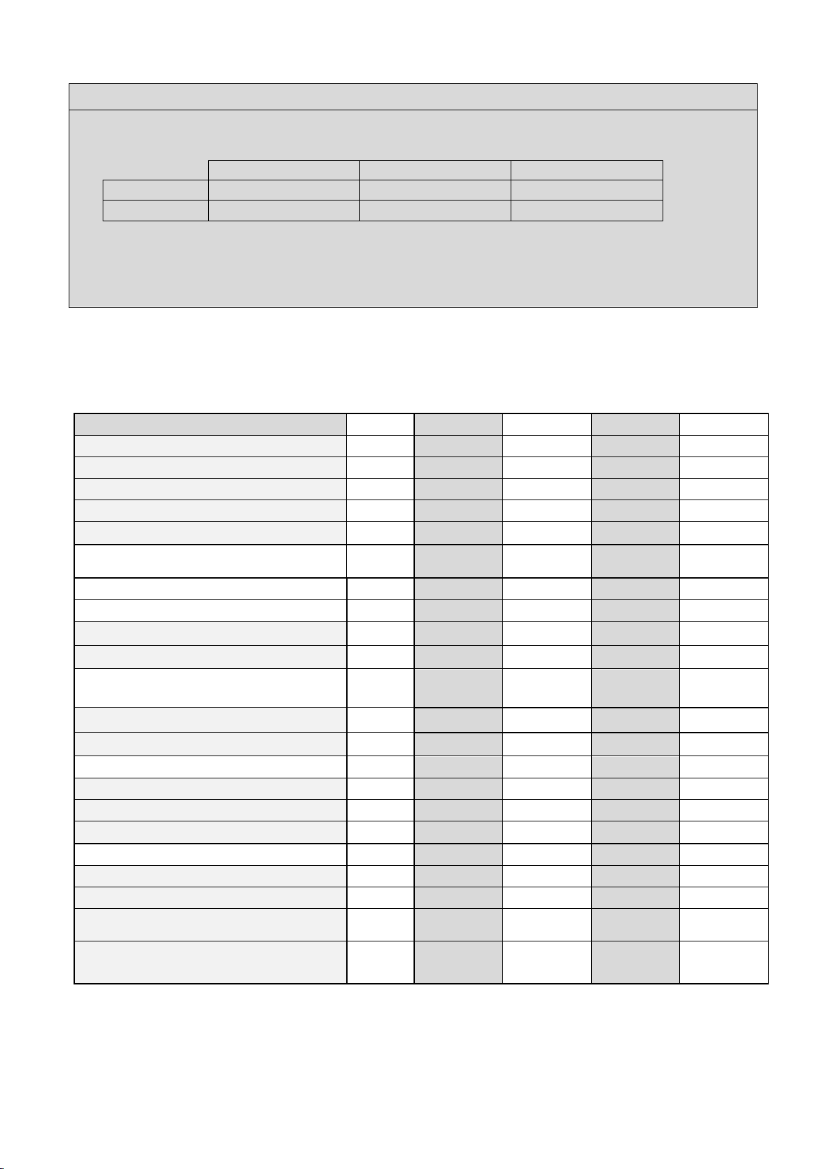
3.2 ErP Specifications Datasheet
Technical parameters according to the European ERP (Energy Related Products) legislation:
Boiler Model:
S-FX 70
S-FX 125
S-FX 220
S-FX 320
Condensing boiler:
Yes
Yes
Yes
Yes
Low temperature boiler:
No
No
No
No
B11 boiler:
No
No
No
No
Cogeneration space heater:
No
No
No
No
Combination heater:
No
No
No
No
Unit:
Value
Value
Value
Value
Rated heat output
kW
64
114
204
295
P-rated (P4) at 60-80 ⁰C
kW
64.4
114.0
204.0
294.5
Heat output (P1) 30% at 30-37 ⁰C
kW
12.8
24.2
41.6
60.6
Seasonal space heating energy
efficiency (ɳs).
%
94.0
94.0
94.0
94.0
Energy efficiency (ɳ4) at 60-80 ⁰C
%
88.5
88.1
88.6
88.7
Energy efficiency (ɳ1) at 30-37 ⁰C
%
98.7
98.8
98.6
98.8
Auxiliary electricity consumption
At full load (elmax).
kW
0.105
0.200
0.260
0.330
At part load (elmin)
kW
0.019
0.025
0.037
0.043
In standby mode (Psb)
kW
0.003
0.003
0.003
0.003
Other
Standby heat loss (Pstby)
kW
0.190
0.300
0.350
0.400
Ignition burner power consumption (P
ign
)
kW
0.000
0.000
0.000
0.000
Emissions (NOx) of nitrogen oxides
(EN15502-1:2012+A1:2015)
1
mg/kWh
18.0
17.0
22.0
20.0
Sound power level, indoors
(EN 15036-1:2006)
dB
58.0
62.0
72.0
76.0
1
These numbers are used to assign credits according to the BREEAM standards
11
4 BOILER DIMENSIONS
4.1 S-FX 70
4.2 S-FX 125
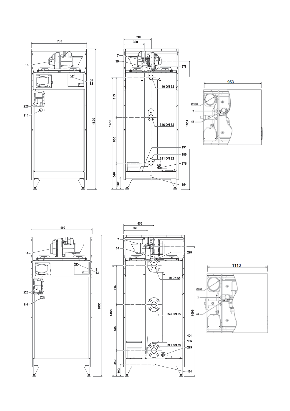
12
4.3 S-FX 220
4.4 S-FX 320

13
5 INSTALLATION OF THE S-FX BOILERS
5.1 General Notes
The S-FX boiler is mounted on a pallet with a wooden “support” frame around it. The boiler is wrapped in shrink
warp before the wooden support frame is mounted. After the frame is placed the whole pallet, boiler and frame
package is shrink wrapped again.
Only remove this packaging when the boiler has been positioned at the place where it will be installed. After
removing the wrapping and the frame, the boiler can be taken off the pallet using a forklift or another suitable lifting
device.
Positioning
The boiler will now be positioned on the four adjustment bolts.
Ensure the boiler levels in both directions are horizontal by using these four bolts.
5.2 Boiler Room
5.2.1 GENERAL
The S-FX range must be installed in a suitable room with ventilation openings direct to outside air in conformity
with the current regulations. If there are several other heat generators that can work together in the same room,
the ventilation openings must be sized to allow all heat generators to operate simultanously.
The place of installation must be free of flammable materials or objects, corrosive gases, powders or voltile
substances. The installation room must be dry and not exposed to rain, snow or frost.
5.2.2 BOILER ROOM
For the installation of the boiler(s) the following demands regarding the boiler room should be considered:
1. The radiation losses of the unit are low.
2. The boiler has a built-in fan that will generate noise, depending on the heat demand. The sound emissions
are quite low from the boiler but be aware that some noise is produced.
3. You need a power supply of at least 230V-50 Hz with an earth connection and may need a supply of 400V-
50Hz depending on the pump. We advise to install a separate “safe working switch on which all poles are
switched” externally so one can work on the boiler while having all the wiring free of supply voltage.
4. The air supply of the boiler will be drawn in from the boiler room.
Other considerations related to the boiler location.
• The ventilation of the boiler room must meet all applicable standards and regulations, regardless of the
selected supply of fresh air to the boiler location.
• The flue gas tube must be connected to an outside wall or roof duct. The air supply is required to come
from outside into the plant room via correctly sized vents / ducts.
• The installation area must be dry and frost-free.
• There must be sufficient lighting available in the boiler room to work safely on the boiler.
• Mind the positioning of electrical components in relation to the temperature sensitivity.
• Make sure there is an open connection with the sewer to drain the condensate. This connection should
be lower than the condensate drain level of the boiler.
• Ensure that the correct space is provided when positioning the boiler for maintenance and replacement of
parts. The recommended minimum clearance is:
- Side clearance: 50 mm
- Front clearance: 500 mm
- Rear clearance: 500 mm
- Above clearance 200 mm
• Make sure that the floor on which the boiler is placed can hold the weight of the boiler.
The S-FX range is strictley prohibited to be installed outdoors, unless adequately protected against
atmospheric agents.
14
6 CONNECTIONS
6.1 Boiler connections
S-FX
S-FX 70
S-FX 125
S-FX 220
S-FX 320
Flow Connection Size
1 ¼" Threaded
1 ¼" Threaded
2" Threaded
DN65 Flanged PN16
Primary Return Connection Size
1 ¼" Threaded
1 ¼" Threaded
2" Threaded
DN65 Flanged PN16
Secondary Return Connection Size
1 ¼" Threaded
1 ¼" Threaded
2" Threaded
DN65 Flanged PN16
Gas Connection
3/4”
1”
1”
1”
15
6.2 Gas Connection
Before making the connection, make sure the S-FX applaince can operate with the type of fuel
available. Clean all the pipes of the gas system to remove any residues that could affect correct
functioning of the boiler.
Connection of the S-FX appliance to the fuel supply must comply with current installation standards.
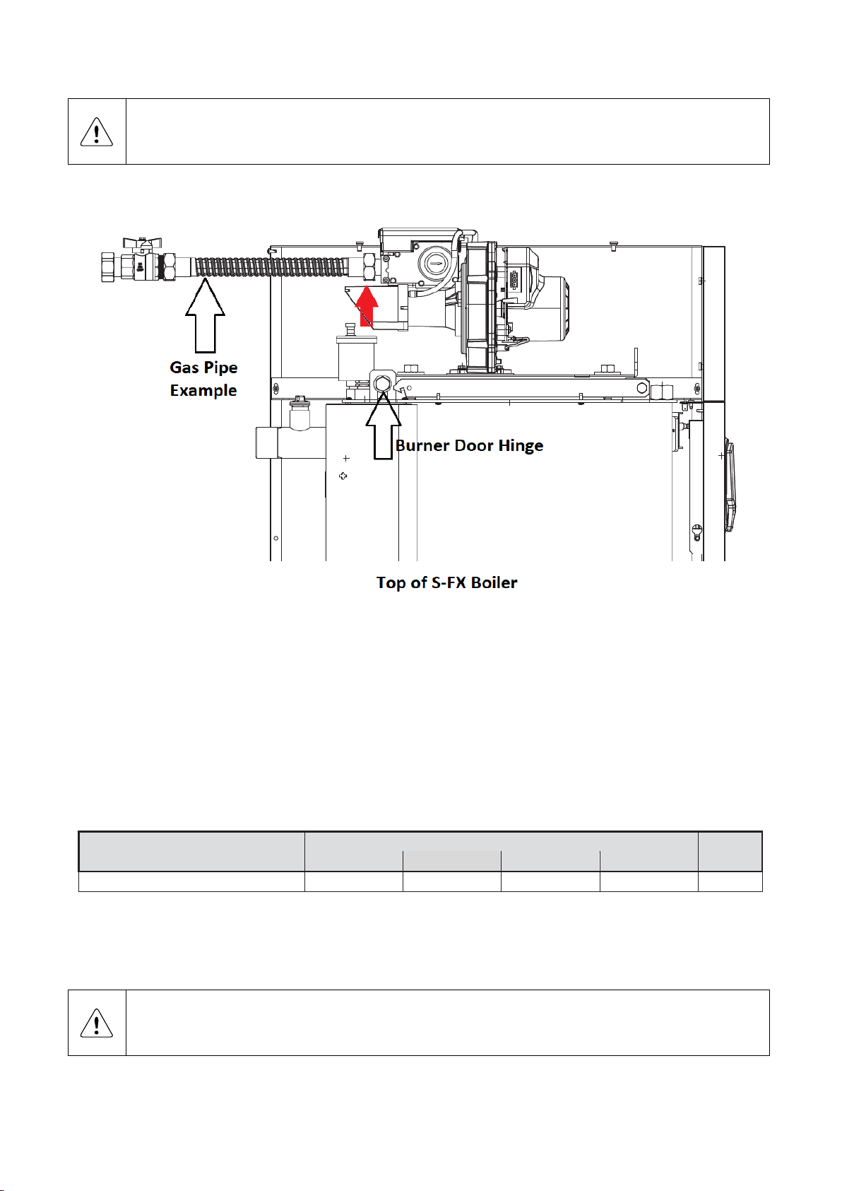
To allow easy opening of the burner door during annual service / maintenance, the last section of the gas pipe must
be considered. See chapter 15.2 which shows how the burner door is opened and closed.
As per the above picture, the red arrow shows where the gas connection to the boiler is located. The burner door
hinge is located directly below thus the gas connection on the S-FX boiler is attached to the fan which is attached to
the burner door that is a moveable part. For the burner door to be opened, the gas pipe connecting into the gas
connection on the boiler will need to be removed. Therefore it is suggested that either:
• The last section is a stainless steel hose with an isolation valve fitted – gas pipe example above.
• The last section of gas pipe work has breakable unions with an isolation valve fitted.
S-FX
S-FX 70
S-FX 125
S-FX 220
S-FX 320
Gas Supply Connection Size
¾"
1"
1"
1"
Ø
Make sure that all gas connections are tight. The capacity of the gas meter must be sufficient for the simultaneous
use of all units connected to it. The diameter of the gas pipe leaving the boiler is not decisive for choosing the
diameter of the pipe between the S-FX unit and the gas meter. It must be chosen according to its length and
pressure drop, in conformity with the current regulations.
Do not use the gas pipes to earth eletrical appliances.
In case of connection in cascade, make sure to install a fuel shut off valve externally with respect to
the modules.
16
6.3 Flow & Return Connections
Before making the connection, carefully flush all the pipes of the system to remove residues or
impurties that could affect the operation of the unit. See “water quailty” and “chemical water
treament” chapters.
S-FX
S-FX 70
S-FX 125
S-FX 220
S-FX 320
Flow Connection Size
1 ¼" Threaded
1 ¼" Threaded
2" Threaded
DN65 Flanged PN16
Primary Return Connection Size
1 ¼" Threaded
1 ¼" Threaded
2" Threaded
DN65 Flanged PN16
Secondary Return Connection Size
1 ¼" Threaded
1 ¼" Threaded
2" Threaded
DN65 Flanged PN16
If the secondary return connection is NOT used then this must be blanked off by the
installation before filling the S-FX appliance.
.
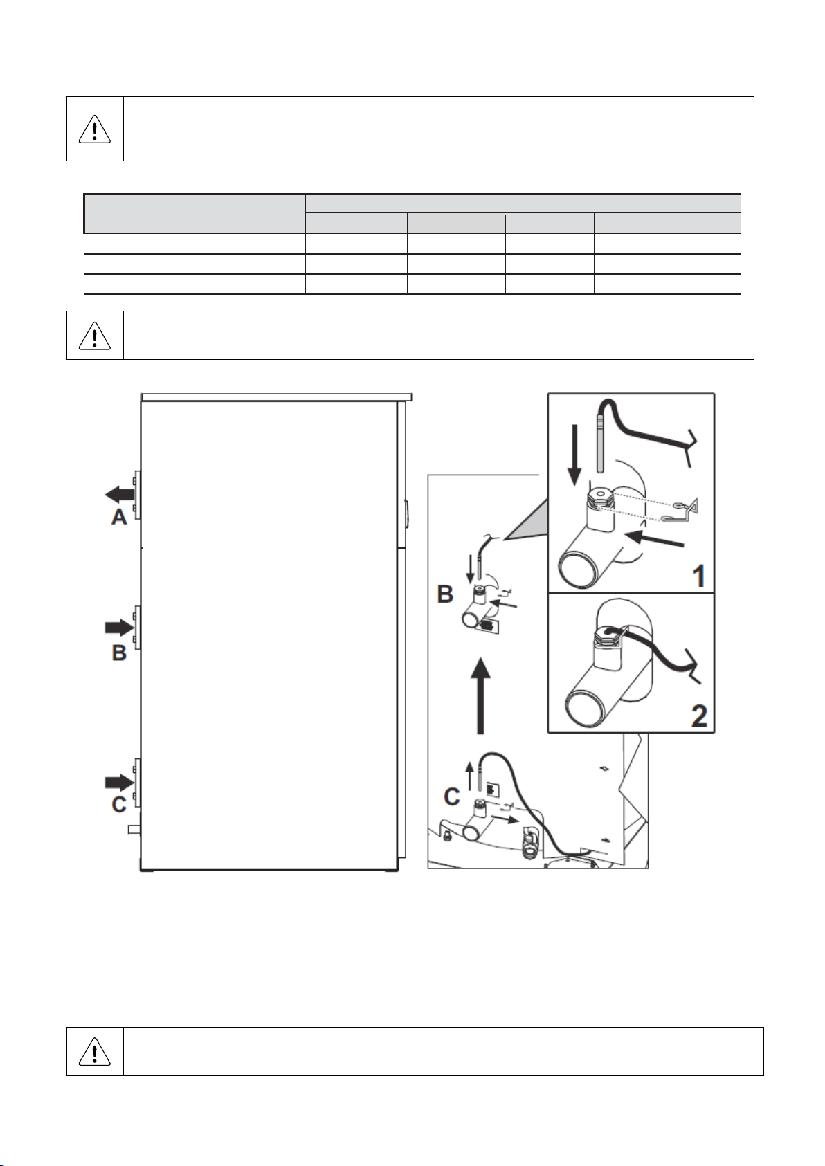
The hydraulic connections are:
• Connection A = Supply / Flow Connection.
• Connection B = High Temperature Secondary Return Connection.
• Connection C = Low Temperature Primary Main Return Connection.
Each return hydraulic connection has a premade pocket for the flow & return sensors to be inserted into as shown
in the above diagram labelled 1 & 2.
Ensure if the primary return connection is only used then insert the return into connection C not B.
Ensure if the secondary return connection is only used then insert the return into connection B not C.
17
6.4 Water quality
The system water must be checked periodically (at least twice a year during the seasons of use, as required by
UNI8065) and possibly have a clear appearance and must be within the following parameters:
• Water PH: From 7 to 8.5.
• Copper Cu (mg/l): < 0.5 mg/l.
• Iron Fe (mg/l): < 0.5 mg/l.
• Chlorides (mg/l): < 50 mg/l.
• Conductivity (µS/cm): < 200µS/cm.
6.5 Chemical water treatment
The chemical compatibility of several products for treatment of the central heating equipment has been tested on
the heat exchangers and the boilers. See below for the list with the corrosion inhibitors in preventative and curative
treatment for gas fired central heating boilers. If water treatment is required when filling the system or preforming
maintenance an inhibitor should be used. Follow the instructions provided by the inhibitor manufacturer when
adding it to the system.
The following is a list of approved chemical treatments.
Corrosion-/ Scale inhibitors and recommended suppliers
Product Types
Fernox
Sentinel
Inhibitors
Protector F1 / Alphi 11
X100, X500
Noise reducer
X200
Universal cleaner
Restorer
X300
Sludge remover
Protector F1, Cleaner F3
X400
Antifreeze
Alphi 11
X500
Tightness
Leaker Sealer F4
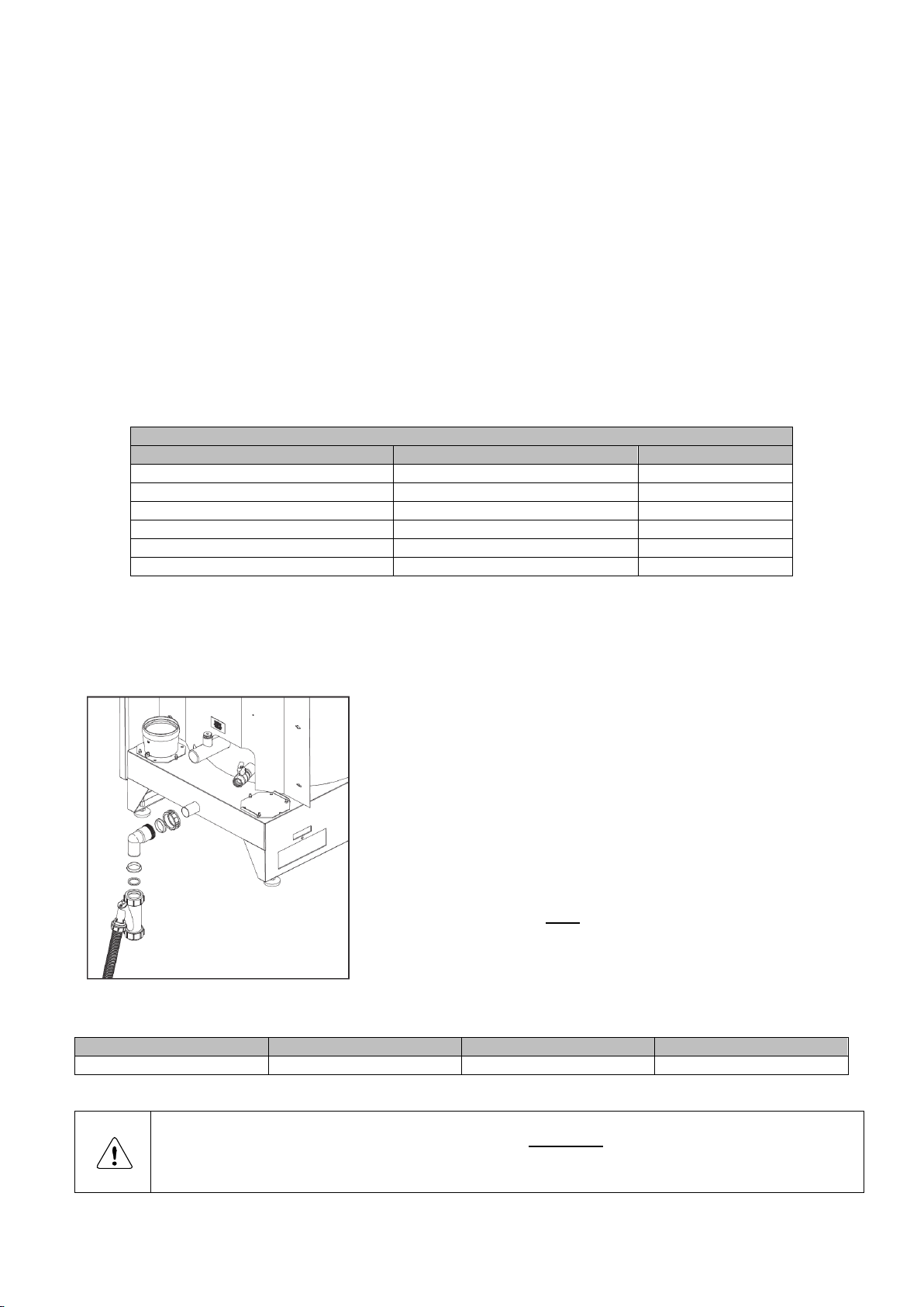
6.6 Condensate Drain
The condense drain is supplied loose within the S-FX boiler casing on delivery, please connect before operating
the boiler.
The condensate drain is placed at the centre and at the bottom of
the boiler and has a hose discharge. Connect this flexible hose to
the sewer system.
Use only plastic parts with the condensate drain. Metal lines are
not allowed.
Blockage of this drain might damage the boiler. The drain
connection is correct when the condensate can be seen flowing
away, e.g. using a funnel. Any damage that might occur, when the
drain is not installed correctly, is not covered by the warranty of the
boiler.
There should be an open connection of the condensate hose into
the sewage system. A possible vacuum in the sewage system
must never give the opportunity to suck on the boiler’s condensate
drain hose.
Maximum condensate flow per S-FX model:
S-FX 70
S-FX 125
S-FX 220
S-FX 320
8.3 litres per hour
14.9 litres per hour
26.7 litres per hour
39 litres per hour
When mounting the bottom part of the condensate trap, before commissioning the boiler and/or after
maintenance, the condensate trap must ALWAYS be completely filled with water.
This is a safety measure: the water in the condensate trap keeps the flue gases from leaking
out of the heat exchanger via the condensate drain.

18
6.7 Expansion Vessel
The capacity of the expansion vessel must be selected and based on the capacity of the central heating system
and the static pressure. Suggested is to fit the expansion vessel in the return pipe of the central heating system.
6.8 Pressure relief valve
The S-FX boiler has no internal pressure relief valve, it is required to be installed as close to the boiler on the flow
pipe of the heating system. When having cascaded boilers, each boiler requires to have its own pressure relief
valve. It is recommended to install isolation valves on the flow and return pipework, so the boiler can be isolated
from the heating system, when needed. Make sure that the pressure relief valve is mounted between the boiler
and the isolation valves.
Alternatively, there is a connection on the S-FX boilers flow pipe just before it connects to the system which is
plugged off. This is primarily used for any BMS temperature sensor require but can be used to connect a safety
valve. But due to the size of the connection, NABIC FIG 500 high lift valves will be required:
- S-FX 70 & 125 = ½” FBSP Connection.
- S-FX 220 = ¾” FBSP Connection.
- S-FX 320 = 1” FBSP Connection.
The specifications and size of the relief valve should be determined by the installer and must comply with all
applicable regulations and boiler capacity.
6.9 NON-Return Flap.
All S-FX boilers have a non-return valve installed on the air pipe just before the internal combustion fan. This gives
protection of flue gas recirculation, but it should not be classed as a prevention of flue gas recirculation as it is not
a non-return valve.
6.10 Bypass
The boiler has no internal bypass. When many thermostatic valves are being used, the system should have a bypass to allow an adequate flow when all thermostatic valves are closed.
Instead of a bypass also a low-loss header or a SMH Boiler Guard can be used for this function.
The boiler flow will also be influenced when a pipe of the heating system is frozen / blocked. Make sure all heating
pipes are free from the risk of frost. If there is the risk of freezing of the heating system, all the pipe section must
be insulated and/or protected with the help of a tracing.
6.11 Frost protection
The boiler has a built-in frost protection that is automatically activating the S-FX boiler and connected heating
pumps when the boiler supply / flow (water) temperature drops below 6 °C.
This frost protection function will not fire up the boiler if the power supply or gas supply has been turned off. If
necessary, for system protection use a suitable antifreeze liquid as listed within chapter 6.5.
NOTICE: A boiler damaged by frost is not covered under warranty.
6.12 Automatic Filling System / Pressurisation Units.
When using an automatic water refill system some precautions should be taken (fresh water is bringing fresh
oxygen into the system), like installing a water meter to measure and evaluate the total water volume that is added
to the system. This to detect and eliminate any water leakage as soon as possible. When an automatic water refill
system is used, some form of logging should take place to prevent continuously filling of the system with large
amounts of oxygenated fresh water. This can happen when a leak in the system is not detected and the total
added water amount is not being logged.
6.13 Water pressure
The installation should be designed and built to conform to all applicable regulations and standards, including the
right safety valves. IMPORTANT: Always keep the pressure in the boiler lower than the value at which its safety
relief valve opens.
Switch
A water pressure switch has been built into the boiler. With this switch, the minimum water pressure in the boiler
is 0.5 bar. The normal water pressure is supposed to be between 1.5 and 2.0 bar.
The pressure sensor will stop the boiler from firing when the water pressure drops below 0.5 bar, and start the
boiler firing again when the water pressure reaches above 1.0 bar.
19
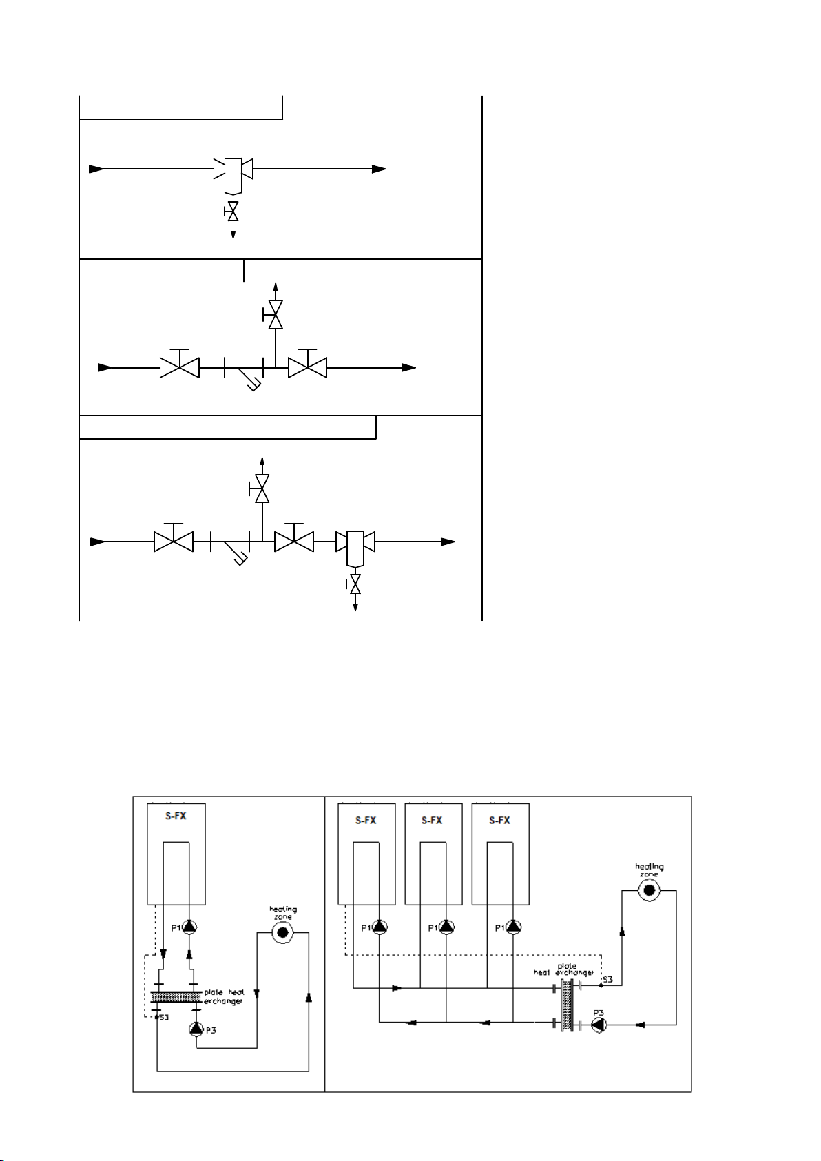
6.14 Installing a strainer and/or dirt separator
Always install a strainer (water filter)
and/or a dirt separator in the return pipe
of the boiler; in such a way that the water
going to the boiler is free of any
debris/particles.
When using a water filter always check
a week after installation to determine the
strainer cleaning interval. Advice is to
mount valves before and after the
strainer, including an air bleed valve, so
the strainer can be isolated from the
heating circuit for service operations.
Clean water is very important, blocked
and/or polluted heat exchangers,
including failures and/or damages
caused by this blockage are not covered
by the warranty.
6.15 Plastic piping in the heating system
When plastic pipes with no oxygen barrier e.g. under-floor heating system, are used in the central heating system,
these should be separated from the boiler system by using a plate heat exchanger. Diffusion (through the plastic)
can cause air to enter the heating system. This could damage the boiler, pumps and other components in the
system. Be aware that plastic piping is often used in under floor heating systems. When no measures have been
taken to prevent the entrance of air into the boiler system, the warranty of the boiler and any boiler part may be
deemed invalid.
SYSTEM WITH DIRT SEPARATOR
SYSTEM WITH STRAINER
SYSTEM WITH STRAINER AND DIRT SEPARATOR
DIRT SEPARATOR
DIRT SE-
PARATOR
WATER
RETURN FROM
SYSTEM
WATER
RETURN
FROM
SYSTEM
WATER
RETURN
FROM
SYSTEM
WATER FLOW TO
BOILER(S)
WATER FLOW TO
BOILER(S)
WATER
FLOW TO
BOILER(S)
DIRT
BLEED
VALVE
DIRT
BLEED
VALVE
AIR
BLEED
VALVE
AIR
BLEED
VALVE
VALVE
VALVE
VALVE
VALVE
STRAINER
(WATER FILTER)
STRAINER
(WATER FILTER)
20
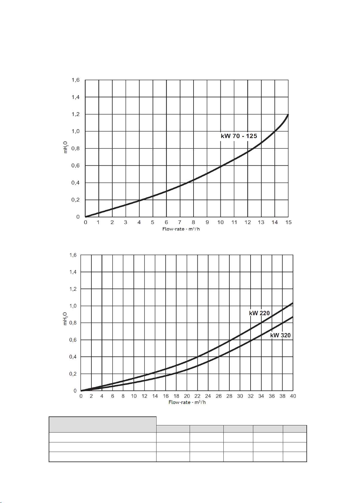
7 BOILER SHUNT PUMP
The S-FX boilers do not have an internal shunt pump therefore using the following graphs, select a pump that is
compatible with the hydraulic resistance of the boiler and the system against the required flow rate.
7.1 S-FX 70 & 125 Hydraulic graph
7.2 S-FX 220 & 320 Hydraulic graph
It is recommended to observe the water flow rates in the table and as specified below.
DESCRIPTION
S-FX 70
S-FX 125
S-FX 220
S-FX 320
Water flow rate ΔT 10
5.52
9.77
17.49
25.29 m3
/h
Water flow rate ΔT 20
2.76
4.89
8.74
12.64 m3
/h
Water flow rate ΔT 40
1.38
2.44
4.37
6.32 m3
/h
21
8 FLUE GAS AND AIR SUPPLY SYSTEM
8.1 General
The S-FX boiler range is a B23 type with combustion air drawn from the place of installation, and exhaust fumes
discharged by means of a combustion fan (operation with flue pressurised) direct to outside air via a flue system.
Description
S-FX Boiler Range
70
125
220
320
Flue Pressure the Fan can Overcome
200
200
200
200
Pa
Notice:
• Install all horizontal flue components with an angle of 3° downwards in the direction of the boiler (roughly
equal to five centimetres for every linear meter). When not installed accordingly, it may result in condensate
building-up in the flue gas tube, eventually causing component failure.
• When using a wall terminal, there is the possible risk of ice building-up on surrounding parts/structures,
because the condensate will freeze. This risk should be taken into account during the design phase of the
heating installation.
• In line flue condensate drains must be used with flue runs longer than 4 meters with the condense drainpipe
going to a sewage system.
• Because the flue gases can have a low temperature, the boiler needs to have a high efficiency approved
stainless steel or plastic flue system. These materials, including the gaskets, should be usable for positive
pressure flue gas systems and have a temperature class of T120. Meaning: the parts must be certified for
use at temperatures of minimal 120 °C (See also warnings below).
Note:
In general, gas heaters are certified with their own flue gas material. The gas heater must be provided with high
efficiency SS or PP flue gas components available. The parts have to be qualified for an overpressure class P1 or
H1 and a temperature class of T120 minimum.
Never use aluminium flue with the S-FX boilers
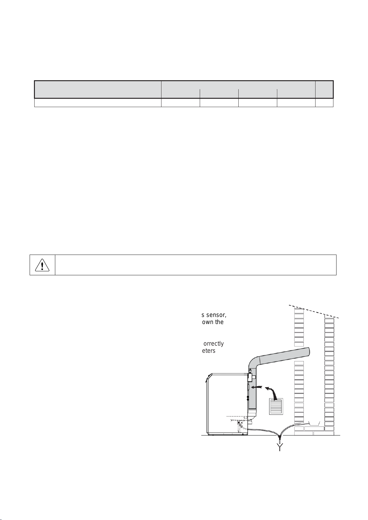
B23 Type
• S-FX appliances are equipped with an exhaust flue gas sensor,
which in the event of irregular temperatures will close down the
operation of the boiler.
• The flue duct must be correctly sized. Inadequate or incorrectly
sized flues will cause problems with combustion parameters
and excessive noise.
• For the flue duct, the use of stainless steel piping is
recommended, in compliance with standards
EN1856-1 and EN1856-2.
• Ensure any horizontal flue runs have a 3 degree fall
back.
• Inline flue condensate drainage points must be
installed connected directly traps with flue runs over
4 metres.
• Common exhaust flues must be sized to a zero pressure
with all but one boiler firing in high fire.
 Loading...