

Strebel S-CBX 85, S-CBX 105, S-CBX 125, S-CBX 155 Installation & Operating Manual
STREBEL
S-CBX Cascade Kits
Models 85 - 105 - 125 - 155
Installation & Operating Manual
2 x 85 up to 6 x 155
Please read and understand before commencing installation and leave the manual with the customer for future reference.
2019-05-01 v1


3
Contents
1. INTRODUCTION........................................................................................................................................ 4
2. INSTALLATION PROCEDURE CASCADE CONFIGURATION .............................................................. 5
3. DETERMINE POWER REQUIRED FOR THE CASCADE CONFIGURATION ........................................ 6
4. CALCULATE DIMENSIONS AND SPACE OF CASCADE CONFIGURATION ...................................... 8
5. EXPLANATION OF PARTS AND GROUPS .......................................................................................... 11
6. CONNECTING SETS .............................................................................................................................. 12
7. HYDRAULIC AND GAS HEADER GROUP ............................................................................................ 13
7.1 Headers ........................................................................................................................................... 13
7.2 Support beam and support brackets ............................................................................................... 13
7.3 Headers and connecting sets .......................................................................................................... 14
8. MOUNTING THE FRAME ....................................................................................................................... 15
8.1 Frame elements .............................................................................................................................. 15
8.2 Procedure for mounting the frame .................................................................................................. 16
9. MOUNTING THE GAS HEADER ............................................................................................................ 17
10. MOUNTING THE BOILERS ON THE FRAME ........................................................................................ 18
11. MOUNTING THE HYDRAULIC GROUP AND THE CONNECTING SETS ............................................ 19
12. MOUNTING THE LOW LOSS HEADERS .............................................................................................. 20
13. DETERMINE MANAGING AND DEPENDING BOILERS ...................................................................... 21
14. COMPLETE THE MECHANICAL INSTALLATION ................................................................................ 21
15. MOUNT THE FLUE GAS AND AIR SUPPLY SYSTEMS....................................................................... 22
15.1 Individual flue systems .................................................................................................................... 22
15.2 Common flue system ....................................................................................................................... 22
16. SET PARAMETERS ................................................................................................................................ 23
17. COMMISSIONING THE CASCADE CONFIGURATION ........................................................................ 23
18. ACCESSORIES ....................................................................................................................................... 24
19. REFERENCES......................................................................................................................................... 24
19.1 List of figures ................................................................................................................................... 24
19.2 List of tables .................................................................................................................................... 24
20. APPENDIX A – CASCADE PARTS ........................................................................................................ 25

4
1. Introduction
This cascade manual is intended for the wall-hung high efficiency central heating boilers from the S-CBX boiler
series as manufactured by Strebel Ltd
The boilers can be combined in one cascade configuration. This ensures that the required power can always be
achieved. Since several boilers are combined this allows for a deeper modulation range and for more precisely
achieving the required level.
Furthermore, the cascade configuration offers an increased reliability: should one boiler go into error, the
cascade configuration will continue to operate.
Strebel Ltd can supply standard cascade systems with mounting frame, piping and low loss headers for up to six
boilers depending on the range. Larger amounts of boilers in a cascade combination are possible but require a
dedicated system which must be designed separately.
The software allows for combining of up to 16 S-CBX boilers in a single cascade installation.
This document will offer you a general procedure for the complete installation of a cascade configuration.
For specific details regarding connections, parameters, venting, etc. see the Installation & Service Manual of the
boilers.
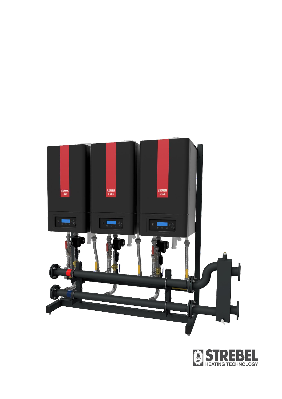
Figure 1.1 Two S-CBX boiler cascade configuration.

5
2. Installation Procedure Cascade Configuration
In order to completely install a cascade configuration of two or more boilers, the following procedure should be
observed:
1. Calculate the total required amount of power for the cascade configuration and determine the
number of boilers necessary in the cascade configuration to achieve the required power.
This is described in detail in chapter 3.
2. Determine the dimensions of the cascade set and the required space at the planned location.
This is described in detail in chapter 4.
3. Mount the frame.
This is described in detail in chapter 8.
4. Mount the gas header.
This is described in detail in chapter 9.
5. Mount the boilers on the frame.
This is described in detail in chapter 10.
6. Mount the hydraulic group and the connecting sets.
This is described in detail in chapter 11.
7. Mount the low loss header.
This is described in detail in chapter 12.
8. Determine which boiler is managing and which are depending.
This is described in detail in chapter 13.
9. Complete the mechanical installation of the cascade configuration.
This is discussed in chapter 14.
10. Mount the flue gas and air supply systems.
This is discussed in chapter 15.
11. Set the parameters in the software by means of the controller of each boiler.
This is discussed in chapter 16.
12. Commission the cascade installation.
This is discussed in chapter 17.

6
3. Determine Power Required for the Cascade Configuration
The first step in the installation procedure for the cascade configuration is to determine the total power required
for the cascade configuration. This power is calculated based on the size of the room(s) to be heated and other
relevant variables. If the required power in kW is known, consult
Table 3.1 (below) in order to determine which combination of boilers can be applied to achieve the required
power.
Total
Power *
S-CBX 85
S-CBX 105
S-CBX 125
S-CBX 155
Total Number
of Boilers
170 2 2 187 1 1 2 204 2
2
210 1 1 2 227 1 1 2 236 1 1
2
249 2 2 253 1 1 2 255 3
3
272 2 1 3 276 1 1 2 289 1 2
3
295 2 1 3 302 2 2 305 3
3
312 1 1 1 3 321 2 1 3 328 2 1
3
335 1 2 3 338 1 1 1 3 340 4
4
351 1 2 3 355 2 1 3 357 3 1
4
361 1 1 1
3
374 3 3 374 2 2
4
378 1 1 1 3 380 3 1 4 387 1 2
3
391 1 3 4 397 2 1 1 4 400 2 1
3
404 1 2 3 406 3 1 4 407 4
4
413 1 2 1 4 420 2 2 4 423 2 1 1
4
426
5
5
427 1 2 3 430 3 1
4
7
Total
Power *
S-CBX 85
S-CBX 105
S-CBX 125
S-CBX 155
Total Number
of Boilers
436 1 1 2
4
440 1 2 1 4 446 2 1 1
4
453 3 3 453 2 2 4 456 3 1 4 459 1 3
4
472 2 2 4 476 1 3
4
479 2 1 1
4
486 1 2 1
4
489 1 1 2 4 499 4
4
502 1 2 1 4 506 2 2
4
511
6
6
512 1 1 2 4 525 3 1 4 529 1 1 2
4
538 1 3 4 551 2 2
4
555 1 3 4 578 1 3 4 604 4 4 624
5
5
650 4 1 5 676 3 2
5
702 2 3 5 729 1 4 5 748
6
6
755
5
5
775 5 1 6 801 4 2
6
827 3 3 6 853 2 4 6 880 1 5 6 906
6
6
* Figures in this column represent the nominal output in kW at 50°C / 30°C
Table 3.1 Cascade power calculation table based on S-CBX boilers.
EXAMPLES
1) In case the required power is calculated at 275 kW, the table will show you that the required cascade
type and that the cascade configuration should have 2 boilers: one S-CBX 125 boiler and one S-CBX
155 boiler.
2) In case the required power is calculated at 440 kW, the table will show you that the required cascade
type and that the cascade configuration should have 4 boilers: one S-CBX 85 boiler, two S-CBX 105
boilers and one S-CBX 155 boiler.
8
4. Calculate Dimensions and Space of Cascade Configuration
In this chapter is explained how to determine the dimensions of the cascade configuration and how much space
is required in the room where the cascade configuration will be installed.
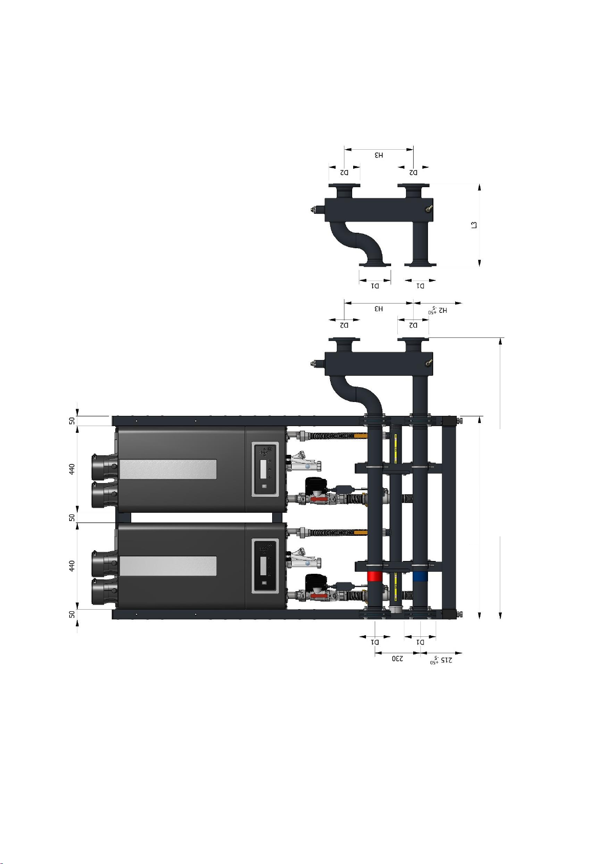
Figure 4.1 Dimensions front view
L2 (length incl. low loss header)
L1 (length)
)frame)
EHS.T0200.5050

9
Figure 4.2 Dimensions: Side views
After you have determined which cascade configuration will be applied and therefore how many boilers must be
combined in the cascade configuration, the next step is to determine the total dimensions of the cascade
configuration and the space required for the cascade configuration.
Figure 4.1 and Figure 4.2 show a schematic representation of a cascade configuration. The dimensional
references in this figure (L1-L3, H1-H3, D1-D3, A, B) correspond with the dimensional references in the tables
below.
EXAMPLES
In case a cascade configuration for 275 kW is required, which will exist of 2 boilers, refer to Table 4.1 for the
dimensions of the cascade configuration. The table shows that frame length for this configuration is 1030 mm
and the total length including the low loss header is 1428 mm.
In case a cascade configuration for 440 kW is required, which will exist of 4 boilers, refer to Table 4.2 for the
dimensions of the cascade configuration. The table shows that frame length for this configuration is 2010 mm
and the total length including the low loss header is 2408 mm.
All these dimensions have to be taken into account when determining the space required for placing the
cascade configuration.
EHS.T0200.5050
 Loading...