

Strebel S-CB 60, S-CB 100, S-CB 80, S-CB 120, S-CB PX 120 Installation & Operating Manual
...Page 1

STREBEL
S-CB+ Cascade Kits
Models +60 - +80 - +100 - +120 – PX 120 - +150 - +180
Installation & Operating Manual
2x60 up to 12x180
Please read and understand before commencing installation and leave the manual with the customer for future reference.
2017-05-01 v1
Page 2

Page 3

INDEX
INTRODUCTION ....................................................................................................................................... 5
1.
2. CASCADE SELECTION TABLE .............................................................................................................. 6
3. MAIN DIMENSIONS.................................................................................................................................. 8
4. EXPLANATION OF PARTS AND GROUPS .......................................................................................... 10
5. FRAME GROUPS ................................................................................................................................... 11
6. MOUNTING THE BOILERS ON THE FRAME ....................................................................................... 13
7. MOUNTING THE CONNECTING SETS ................................................................................................. 14
8. MOUNTING THE HYDRAULIC GROUP ................................................................................................ 16
8.1 Hydraulic group for 2 boilers S-CB+ 60–120 and/or S-CB PX 120 ................................................. 17
8.2 Hydraulic groups for 3 and 4 boilers S-CB+ 60–120 and/or S-CB PX 120 ..................................... 18
8.3 Hydraulic groups for 2 and 3 boilers S-CB+ 150–180 ..................................................................... 19
8.4 Hydraulic group for 4 boilers S-CB+ 150–180 ................................................................................. 20
8.5 Hydraulic groups for 5 and 6 boilers S-CB+ 150–180 ..................................................................... 21
9. LOW VELOCITY HEADERS .................................................................................................................. 22
10. FLUE GAS AND AIR SUPPLY ............................................................................................................... 24
10.1 Individual or common flue systems ................................................................................................ 24
10.2 Individual flue systems .................................................................................................................... 24
10.3 Common flue systems .................................................................................................................... 24
10.4 Installation examples flue gas systems. ......................................................................................... 25
11. INSTALLATION ...................................................................................................................................... 26
12. PARAMETERS ....................................................................................................................................... 28
12.1 Parameter settings for cascaded boilers ........................................................................................ 28
12.2 Control panel / display unit ............................................................................................................. 29
12.3 Setting the parameters using the control panel .............................................................................. 30
12.4 Monitor screens .............................................................................................................................. 31
13. CASCADE CONTROL ............................................................................................................................ 32
13.1 Output control ................................................................................................................................. 32
13.2 Boiler sequence .............................................................................................................................. 32
14. OPTIONS ................................................................................................................................................ 33
3
Page 4

4
Page 5
1. Introduction
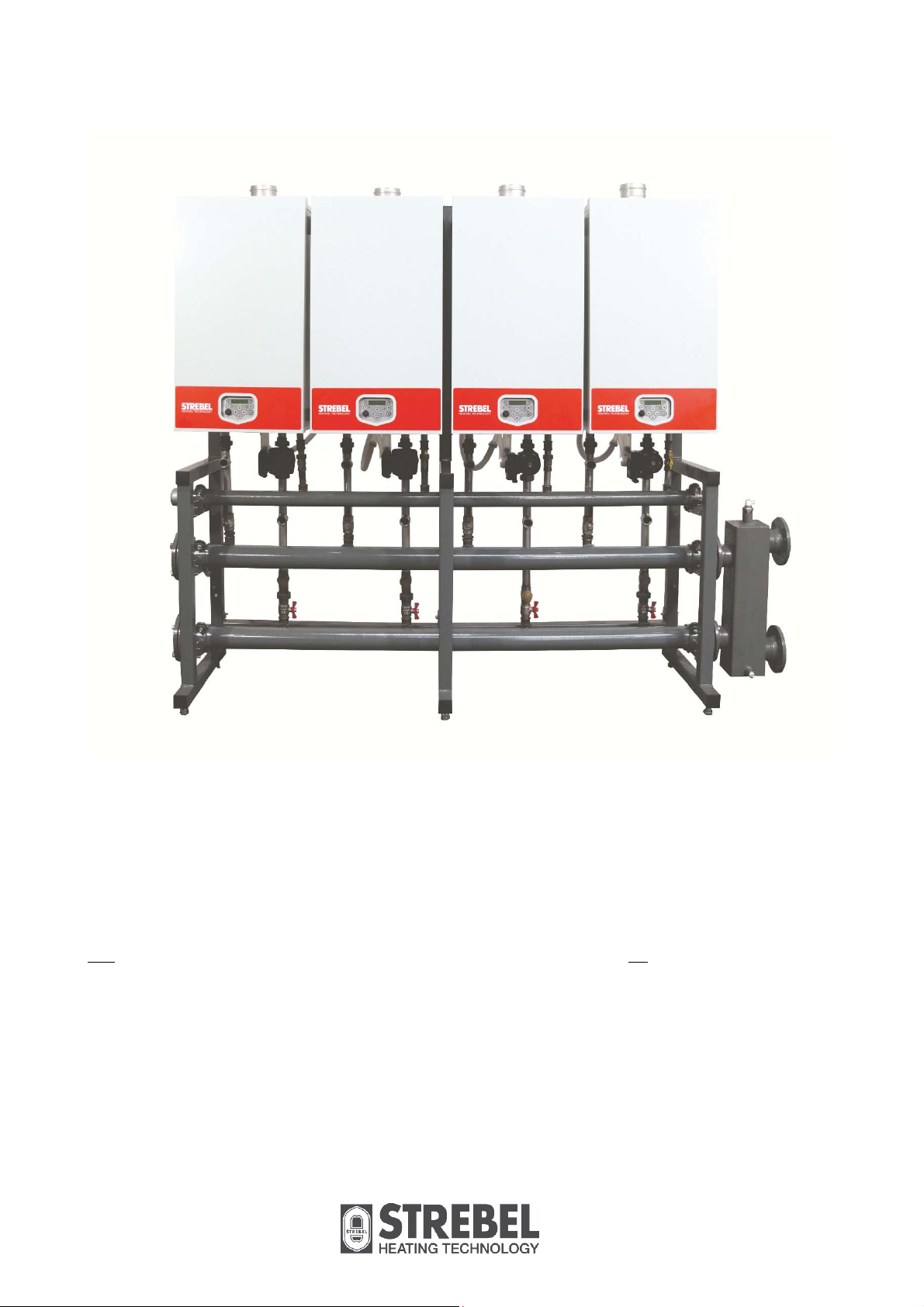
Figure 1 - Typical cascade configuration (S-cb PX 120 Above).
+
This Cascade manual is intended for the S-CB
by Strebel Ltd. These boilers are available, in order of ascending output, as S-CB
PX120,
+
150 and +180.
and the S-CB PX 120 wall-hung high efficiency CH boilers
+
60, +80, +100, +120,
The S-CB 60+ - 120+ (Not including the PX models) can be combined in one cascade set, as can the S-cb+
150-180 boilers, but the S-CB PX 120 models can only be combined with the PX 120 model.
Strebel Ltd can supply standard cascade systems with mounting frame, piping and low loss headers for up to
four boilers in the 60-120 range, four boilers in the PX 120 range and even six in the 150-180 range. For
cascades with more boilers, a dedicated system must be designed.
The Strebel S-CB+ boilers are standard equipped with an internal cascade manager for up to twelve boilers.
No extra controllers are necessary, only connect a 2-wire cable between all boilers.
The low-loss header can be fitted on the right-hand side as well as on the left-hand side without making any
alterations to the delivered parts. The gas connection can also be fitted on one of both sides, independently
from the side chosen for the low loss header.
To commission the cascade installation, it is necessary to set a number of parameters on the boilers, see
chapter 12.1.
5
Page 6
2. Cascade Selection Table
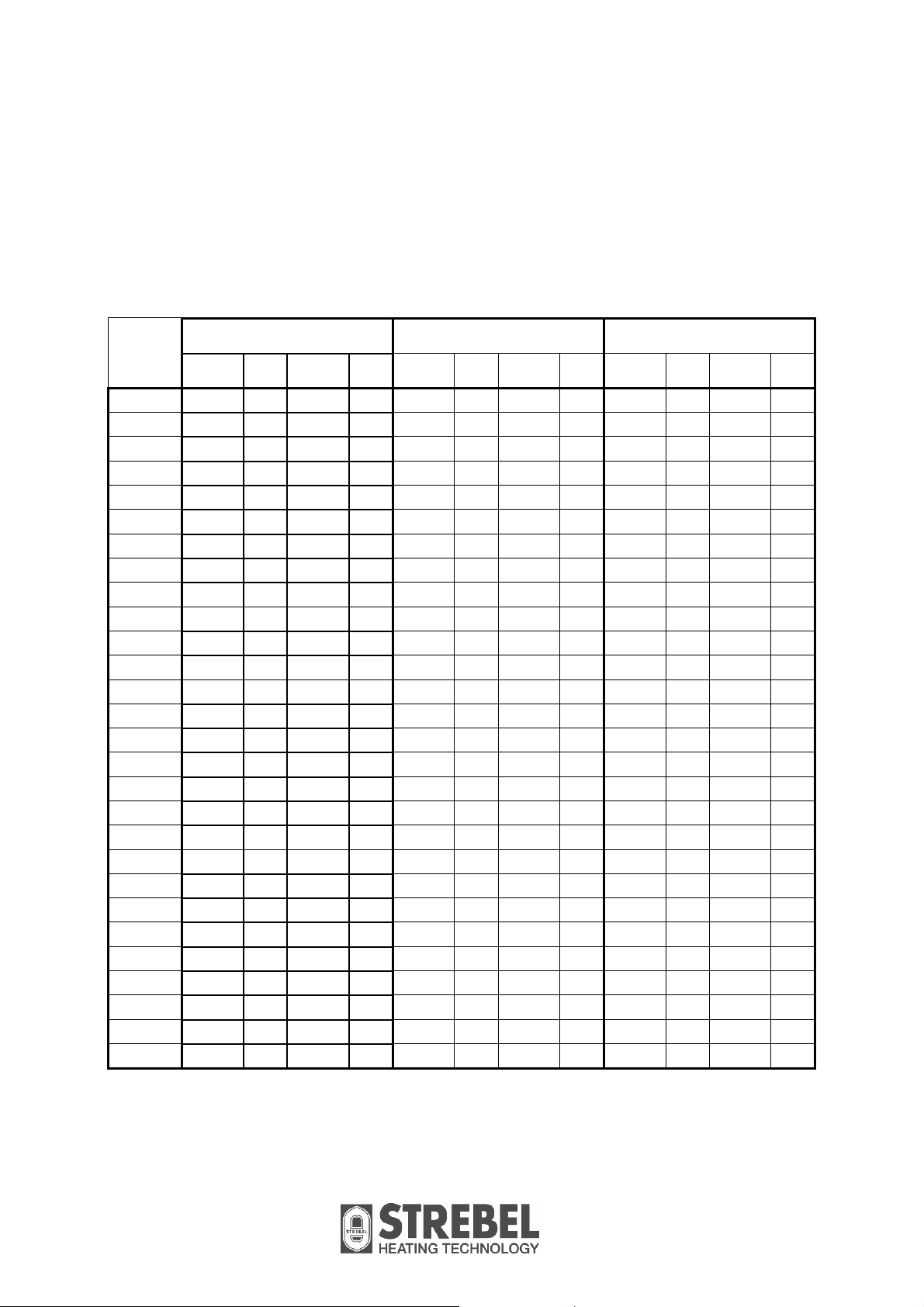
When selecting a cascade set-up, follow the next steps:
1. First determine the total required power of the set.
2. Determine the best number of boilers required (q. in the table(quantity)).
3. Choose one of the combinations in the table below (even more combinations are available).
4. Determine the required space for the set in the main dimensions’ tables and check this with the
planned location.
5. Determine the required flue gas and air supply lines.
6. Choose all the required accessories in the Options-chapter.
Total
Kw
Input
120
140
160
180
200
220
240
260
280
300
320
330
340
360
380
400
420
440
450
460
480
510
540
600
630
660
690
720
Model q. Model q. Model q. Model q. Model q. Model q.
+
+
+
+
+
+
+
+
+
+
2 Boilers 3 Boilers 4 Boilers
60 2x
80 1x
80 2x
100 1x
100 2x
120 1x +100 1x
120 2x
150 2x
180 1x +150 1x
180 2x
+
60 1x
+
80 1x
+
60 3x
+
80 1x
+
80 2x
+
80 3x
+
100 1x
+
100 2x
+
100 3x
+
120 1x +100 2x
+
120 2x +100 1x +100 1x
+
120 3x
+
150 3x
+
180 1x +150 2x +120 4x
+
180 2x +150 1x
+
180 3x
+
60 2x
+
60 1x
+
60 4x
+
80 2x
+
80 1x
+
80 1x
+
80 2x
+
80 3x
+
80 4x
+
100 2
+
100 3x
+
100 4x
+
120 1x +100 3x
+
120 2x +100 2x
+
120 3x +100 1x
+
150 4x
+
180 1x +150 3x
+
180 2x +150 2x
+
180 3x +150 1x
+
180 4x
+
60 3x
+
60 2x
+
60 1x
+
80 3x
+
80 2x
+
80 1x
* Figures in this column are the gross calorific values in kW at 100% load
Table continues next page
6
Page 7

Continuation from previous page
Total
5 Boilers 6 Boilers
Kw
Input
750
780
810
840
870
900
930
960
990
1020
1050
1080
Model q. Model q. Model q. Model q.
+
150 5x
+
180 1x +150 4x
+
180 2x +150 3x
+
180 3x +150 2x
+
180 4x +150 1x
+
180 5x
+
150 6x
+
180 1x +150 5x
+
180 2x +150 4x
+
180 3x +150 3x
+
180 4x +150 2x
+
180 5x +150 1x
+
180 6x
7
Page 8
3. Main dimensions
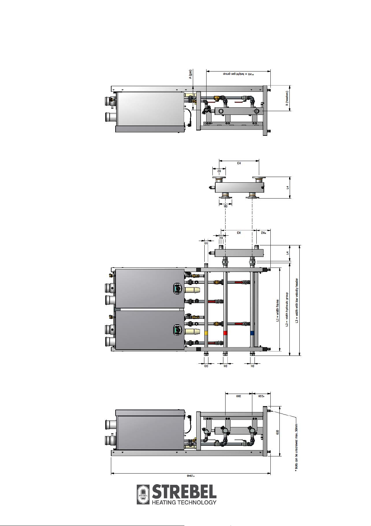
boilers – for the S-CB PX boilers the connecting sets are different.
+
8
Figure 2. Cascade dimensions. The picture shows connecting sets for S-CB
Page 9
1980
4 boilers
889
770
3045
3162
6 boilers
2489
5 boilers
290
791
768
2084
2393
440
DN 80 PN6 (3")
DN 80 PN6 (3")
R 2"
283
283
1980
4 boilers
4071
2607
2090
889
3516
355
2465
220
1000
DN 125 PN6 (5")
DN 125 PN6 (5")
770
220
1000
DN 125 PN6 (5")
DN 125 PN6 (5")
768
168
440
DN 100 PN6 (4")
DN 100 PN6 (4")
335
294
DN 80 (3")
335
294
DN 80 (3")
338
283
DN 80 (3")
1520
3 Boilers
1015
2 Boilers
120
+
60 -
+
265
789
766
1630
1914
190
1140
1358
787
487
DN 65 PN6 (2½")
DN 65 PN6 (2½")
766
436
R 1½"
RP 1½"
283
R 1½"
271
R 1¼"
283
3 boilers
283
2 boilers
180
+
150 -
+
290
766
165
1520
1630
1940
265
1015
1125
1408
766
440
DN 80 PN6 (3")
DN 80 PN6 (3")
144
487
DN 65 PN6 (2½")
DN 65 PN6 (2½")
R 2"
R 2"
338
283
338
283
S-CB Boilers
L1 (frame)
L2 (standards)
L3 (total)
L4 (open header)
H1 (gas)
H2 (open header)
H3 (open header)
D1 (Header Connections Sizes)
D2 (Header Connections Sizes)
D3 (gas)
A (gas)
B (headers)
S-CB Boilers
L1 (frame)
L2 (standards)
L3 (total)
L4 (open header)
H1 (gas)
H2 (open header)
H3 (open header)
D1 (Header Connections Sizes)
D2 (Header Connections Sizes)
D3 (gas)
A (gas)
B (headers)
9
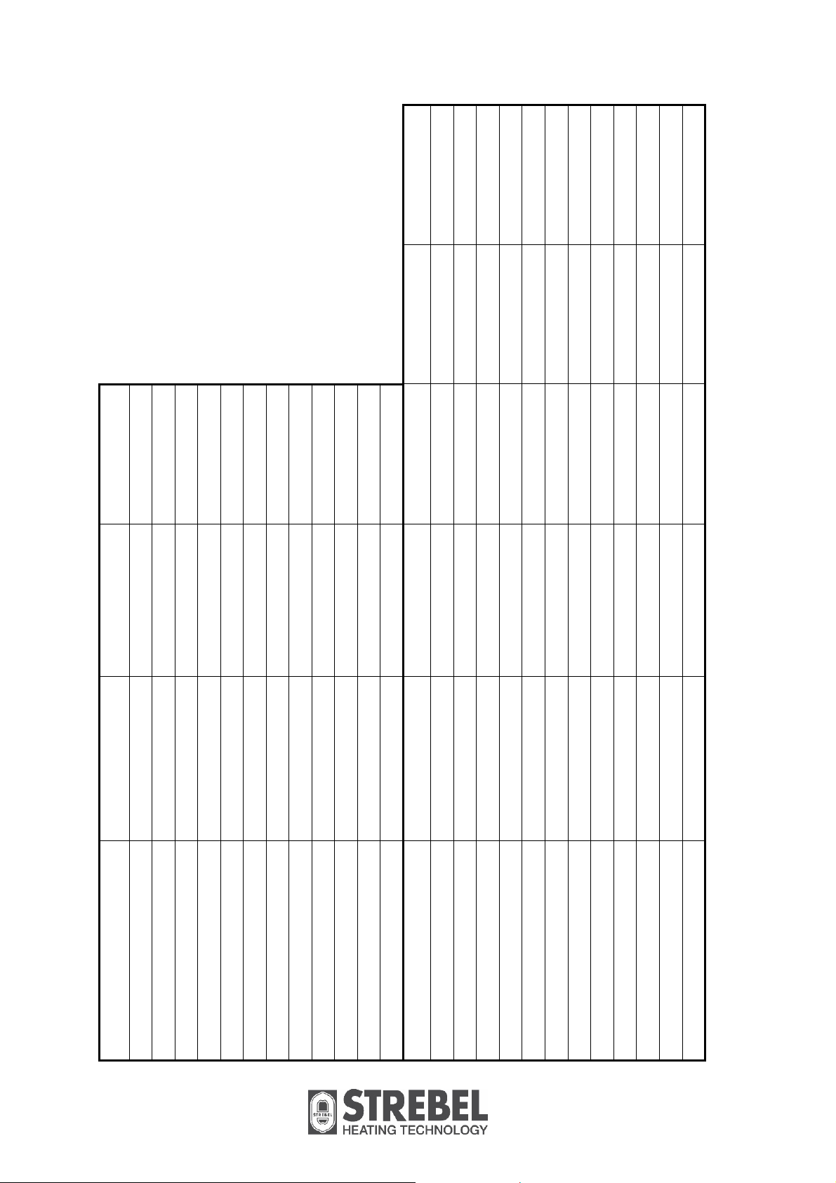
Table 1. Main dimensions (mm and " ).
Page 10
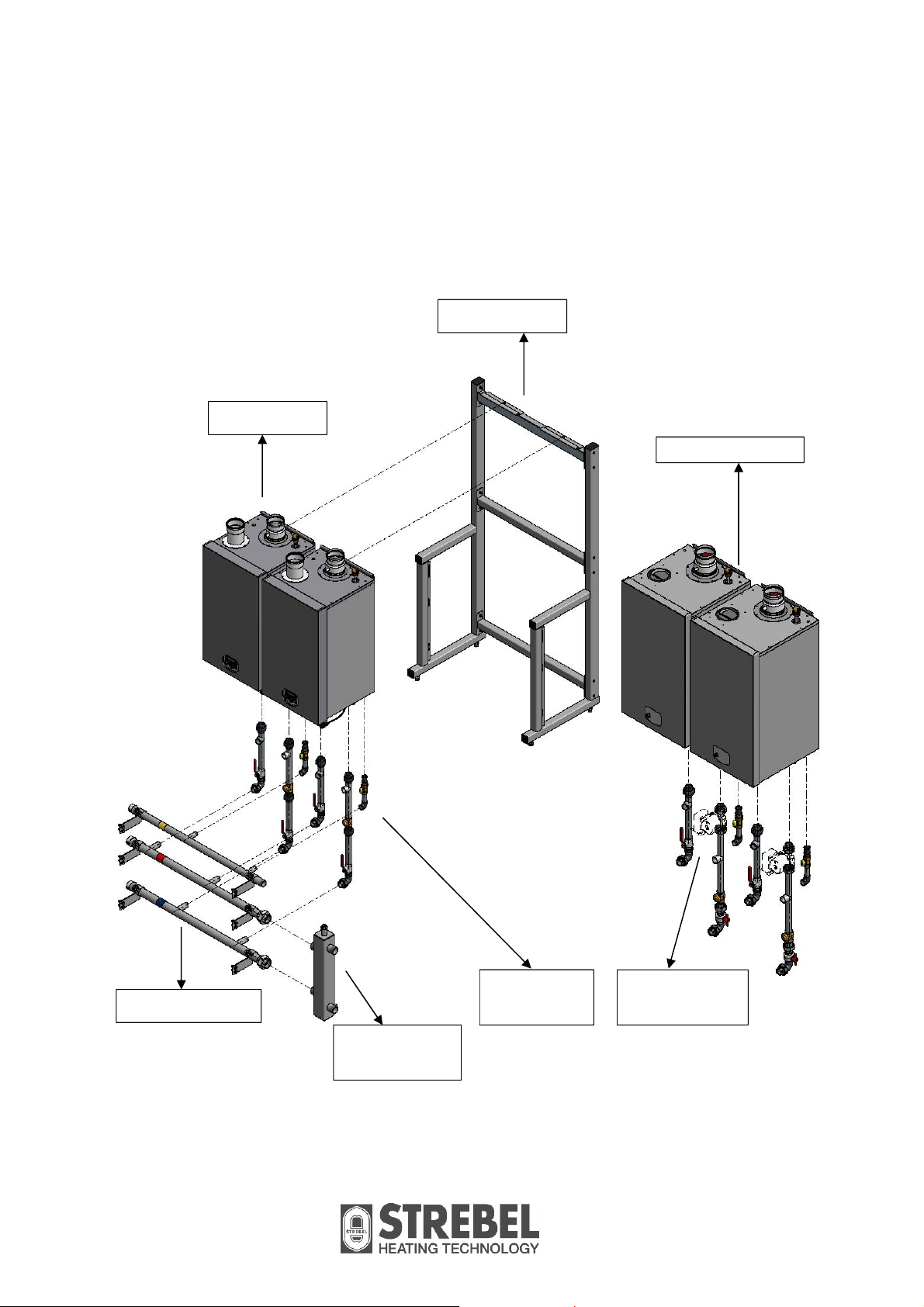
4. Explanation of parts and groups
Each cascade set exists of the following parts and groups:
1. The number of S-CB
2. The frame group (with locking plates) as determined by the number of boilers.
3. Connecting groups to connect the boilers to the hydraulic groups (one group for each boiler, each group
existing of 1 gas, 1 flow and 1 return connecting set).
4. Hydraulic group, existing of 1 gas, 1 flow and 1 return header with all fixing and connecting parts.
5. Low-loss header to connect hydraulic group to your heating installation.
+
type boilers as selected in chapter 2.
S-CB+ Model
Frame group
-
Hydraulic Group
Connecting
sets S-CB
+
Connecting
sets S-CB PX
Low Velocity
Header
Figure 3. Cascade parts and groups. For the S-CB PX boilers, the return connecting sets are different from the S-CB
10
+
.
Page 11
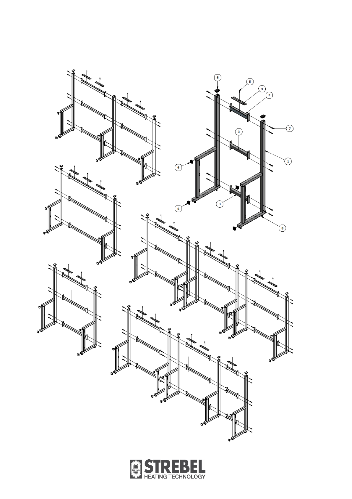
5. Frame groups
Figure 4. Cascade frame groups for 1, 2, 3, 4, 5 and 6 boilers.
11
Page 12

E00.000.158 E00.000.159 E00.000.160
Frame 1 Boiler Frame 2 Boilers Frame 3 Boilers
Pos Description part.no. q part.no. q part.no. q
1 standard E02.040.004 2 E02.040.004 2 E02.040.004 2
2 upper beam E02.040.005 1
upper beam E02.040.006 1
upper beam E02.040.007 1
3 mid/lower beam E02.040.008 2
mid/lower beam E02.040.009 2
mid/lower beam E02.040.010 2
4 locking plate E01.004.126 1 E01.004.126 2 E01.004.126 3
5 lock bolt M8 x 35 E06.000.023 1 E06.000.023 2 E06.000.023 3
6 seal plug 70mm x 50mm E05.001.285 2 E05.001.285 2 E05.001.285 2
seal plug 50mm x 50mm E05.001.101 4 E05.001.101 4 E05.001.101 4
7 bolt M8 x 70 M8 x 70 12 M8 x 70 12 M8 x 70 12
bolt M8 x 120
nut M8 M8 12 M8 12 M8 12
washer M8 M8 13 M8 14 M8 15
adjusting bolt standard
8
M16 x 80 M16 x 80 4 M16 x 80 4 M16 x 80 4
E00.000.161 E00.000.207 E00.000.206
Frame 4 Boilers Frame 5 Boilers Frame 6 Boilers
Pos Description part.no. q part.no. q part.no. q
1 standard E02.040.004 3 E02.040.004 5 E02.040.004 6
2 upper beam E02.040.005 1
upper beam E02.040.006 2 E02.040.006 2 E02.040.006 3
upper beam
3 mid/lower beam E02.040.008 2
mid/lower beam E02.040.009 4 E02.040.009 4 E02.040.009 6
mid/lower beam
4 locking plate E01.004.126 4 E01.004.126 5 E01.004.126 6
5 lock bolt M8 x 35 E06.000.023 4 E06.000.023 5 E06.000.023 6
6 seal plug 70mm x 50mm E05.001.285 3 E05.001.285 5 E05.001.285 6
seal plug 50mm x 50mm E05.001.101 6 E05.001.101 10 E05.001.101 12
7 bolt M8 x 70 M8 x 70 18 M8 x 70 18 M8 x 70 12
bolt M8 x 120 M8 x 120 6 M8 x 120 12
nut M8 M8 18 M8 24 M8 24
washer M8 M8 22 M8 29 M8 30
adjusting bolt standard
8
M16 x 80 M16 x 80 6 M16 x 80 10 M16 x 80 12
Table 2. Frame group parts.
12
Page 13

6. Mounting the boilers on the frame
All lines/piping must be mounted free of tension. The weight of all the components should be supported
separately from the boiler so there is no force on the connections. This might influence the mounting position
of the boiler.
Before mounting the boiler on the frame, ensure that the frame is level in both directions. If necessary adjust
with the adjusting bolts on the lower side of the frame (see drawing).
After mounting the boiler on the frame, ensure that the boiler is level. If necessary adjust with the adjusting
bolts on the lower rear side of the back panel. (see drawing).
When the adjusting bolts aren’t sufficient, one needs to fill behind the bolts to get the boiler level. The
levelling margin is between boiler hanging level, and hanging backwards a little.
The boiler should not lean forward in the mounted position.
Lock the suspension bracket with the locking strip to prevent the boiler from falling off the bracket
(see drawing).
Locking
Levelling boiler
Levelling frame
Figure 5. Mounting details.
13
Page 14

7.
Mounting the connecting sets
First connect the connecting sets hand-tight to the boiler connections. In a cascade set-up, do NOT use the
T-pieces delivered with the boilers.
The shortest connecting set should be connected to the gas connection on the boiler.
Make sure to connect the flow connecting set (middle length) to the boiler flow connection (left-side
connection) and the return connecting set (longest) to the boiler return connection (right-side connection).
The open connection in the flow connecting set is meant for a pressure relief valve, and the one in the return
connecting set is to be used for a boiler bleeding valve.
NOTICE: For the S-CB PX 120 boiler the return connecting set differs, because of the external pump.
Flow connecting set Return connecting set
Gas connecting set
Connection to boiler
Connection for
pressure relief valve
Ball valve
Coupling to flow
header
Connection to boiler
Connection for boiler
bleed valve
Check valve
Ball valve
Connection to boiler
Gas isolator
Coupling to gas
header
Coupling to return
header
S-CB PX boiler with
external pump:
Connection to
boiler
Pump location
Connection for
boiler bleed valve
Check valve
Ball valve and
coupling to return
header
Figure 6. Connecting sets.
14
Page 15

Connecting sets for boilers S-CB+ 60 – 120 and S-CB PX 120
+
NOTICE: Return set for the S-CB PX 120 differs from S-CB
Connecting set part.no.
1
boiler 2 boilers 3 boilers 4 boilers
120
Connecting set gas = ¾" E04.000.377 1x 2x 3x 4x
Flow connecting set = 1" E04.000.373 1x 2x 3x 4x
Return connecting set
+
S-CB
= 1"
Return connecting set
S-CB PX = 1"
E04.000.374 1x 2x 3x 4x
E04.000.417 1x 2x 3x 4x
Connection size relief valve and bleed valve: Both Rp 1"
Connecting sets for boilers S-CB+ 150 – 180
Connecting set part.no.
Connecting set gas = 1" E04.000.378 1x 2x 3x 4x 5x 6x
Flow connecting set = 1¼" E04.000.375 1x 2x 3x 4x 5x 6x
Return connecting set = 1¼" E04.000.376 1x 2x 3x 4x 5x 6x
1
boiler 2 boilers 3 boilers 4 boilers 5 boilers 6 boilers
Connection size relief valve and bleed valve: Both Rp 1¼"
Table 3. NB! Part numbers are corresponding to one connecting set, so order the correct quantity of sets.
15
Page 16
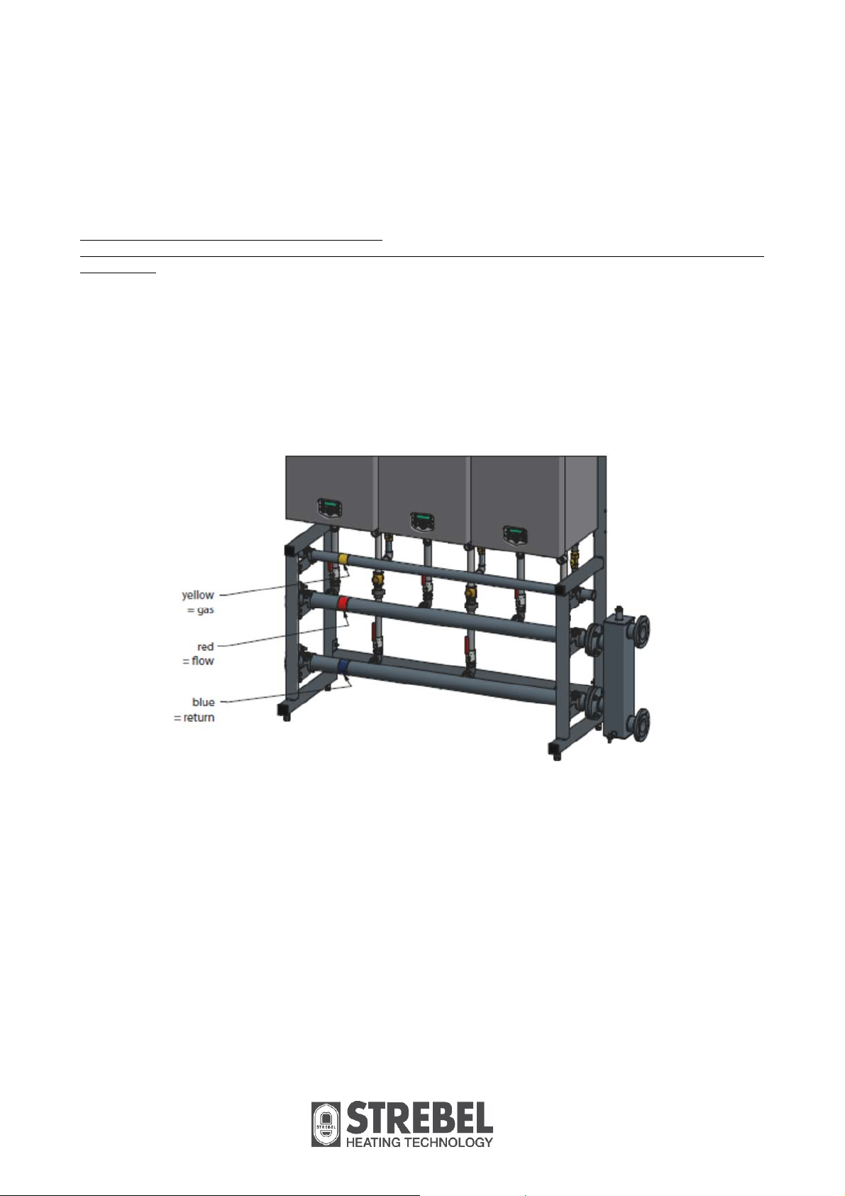
8.
Connect the gas header to the gas connecting sets.
Connect the flow header to the flow connecting sets.
Connect the return header to the return connecting sets.
Mount all headers with the clamps to the frame.
All lines/piping must be mounted free of tension.
The weight of all the components should be supported separately of the boiler so there is no force on the
connections.
This might influence the mounting position of the boiler.
When all parts are mounted in the right place, and are free of tension, fasten all couplings and fasten the
clamps.
Mounting the hydraulic group
Figure 7. Hydraulics.
16
Page 17

8.1 Hydraulic group for 2 boilers S-CB+ 60–120 and/or S-CB PX 120
4
6
7
5
7
5
10
10
10
3
Connecting sets in the picture are S-CB
Hydraulic group for:
1
2
+
versions.
4
5
89
10
5
89
2 Boilers 60–120
E00.000. 152
No. Description Part number Q
1 Gas header E02.025.014 1
2 Flow header E02.032.006 1
3 Return header E02.032.007 1
4 Clamp gas header E01.000.205 2
5 Clamp flow/return header E01.000.208 4
6 Seal cap gas header E04.005.083 1
7 Seal cap flow/return header E04.005.061 2
8 Coupling (2-parts) E04.002.078 2
9 Gasket for coupling E07.003.059 2
10 Bolt + nut + washer M10 x 35 24
17
Page 18
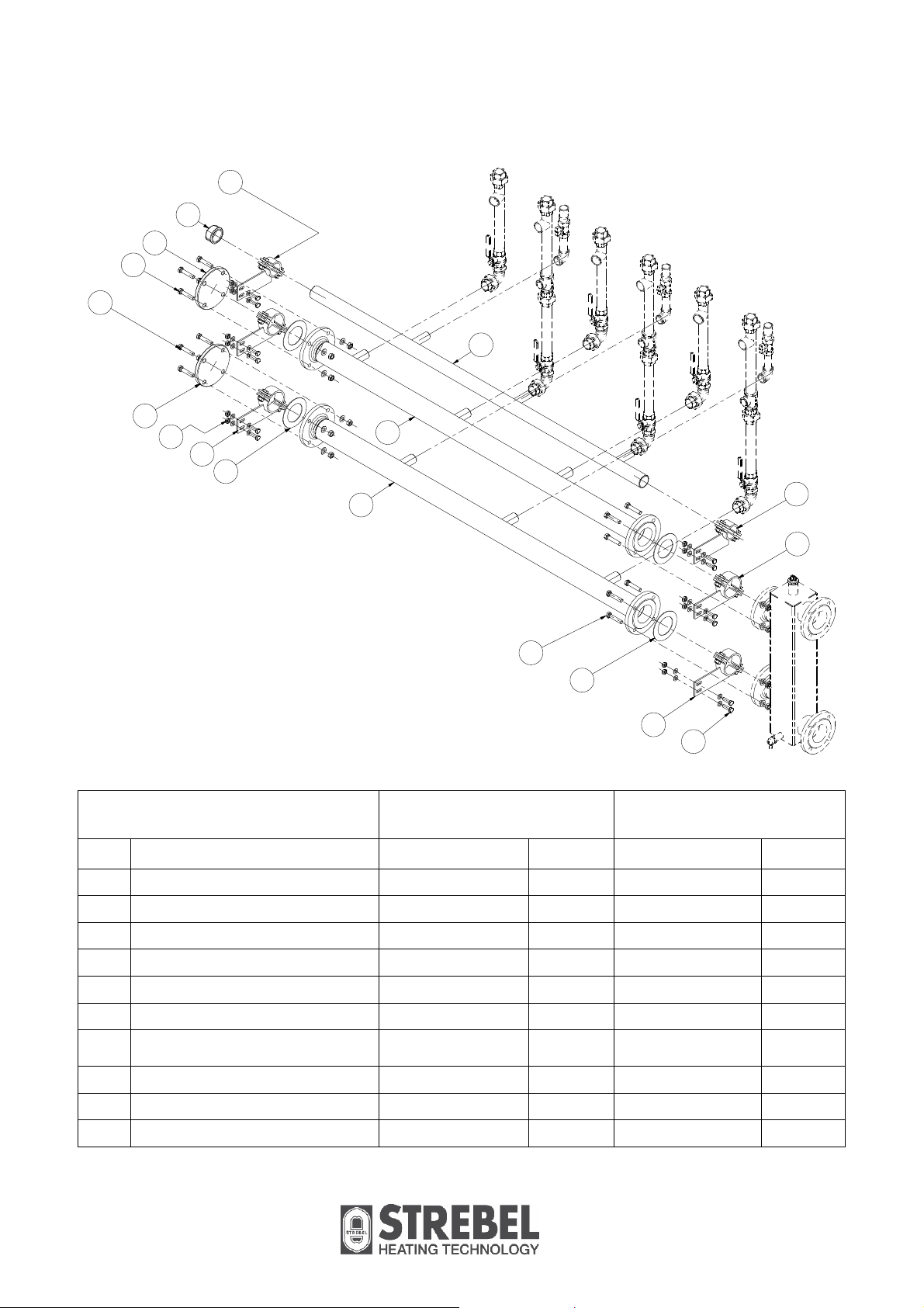
8.2 Hydraulic groups for 3 and 4 boilers S-CB+ 60–120 and/or S-CB PX 120
4
6
7
9
9
1
7
10
5
8
2
3
4
5
9
8
5
10
Connecting sets in the picture are S-CB
+
versions.
Hydraulic group for:
3 Boilers 60–120
E00.000.186
4 Boilers 60–120
E00.000.154
No. Description Part no. Q Part no. Q
1 Gas header E02.032.008 1 E02.027.018 1
2 Flow header E02.039.011 1 E02.028.061 1
3 Return header E02.039.012 1 E02.028.060 1
4 Clamp gas header E01.000.208 2 E01.000.209 3
5 Clamp flow/return header E01.000.210 4 E01.000.211 6
6 Seal cap gas header E04.005.061 1 E04.005.058 1
Blind flange for flow/return
7
header
E04.010.182 2 E04.010.180 2
8 Gasket for flange E07.003.071 4 E07.003.072 4
9 Bolt + nut + washer M12 x 60 16 M16 x 60 16
10 Bolt + nut + washer M10 x 35 24 M10 x 35 36
18
Page 19

8.3 Hydraulic groups for 2 and 3 boilers S-CB+ 150–180
4
6
7
9
5
9
1
7
5
8
3
2
4
9
9
8
10
5
Hydraulic group for:
2 Boilers 150–180
E00.000.155
3 Boilers 150–180
E00.000.156
No. Description Part no. Q Part no. Q
1 Gas header E02.027.019 1 E02.027.017 1
2 Flow header E02.039.009 1 E02.028.056 1
3 Return header E02.039.010 1 E02.028.057 1
4 Clamp gas header E01.000.206 2 E01.000.206 2
5 Clamp flow/return header E01.000.210 4 E01.000.211 2
6 Seal cap gas header E04.005.058 1 E04.005.058 1
5
Blind flange for flow/return
7
header
E04.010.182 2 E04.010.180 2
8 Gasket for flange E07.003.071 4 E07.003.072 4
9 Bolt + nut + washer M12 x 60 16 M16 x 60 16
10 Bolt + nut + washer M10 x 35 24 M10 x 35 24
19
Page 20
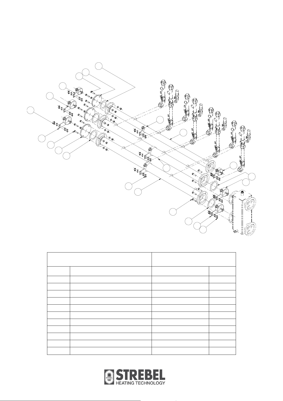
8.4 Hydraulic group for 4 boilers S-CB+ 150–180
7
6
10
4
5
10
4
5
10
8
9
1
11
3
Hydraulic group for:
No. Description Part no. Q
1 Gas header E02.028.058 1
2 Flow header E02.031.005 1
3 Return header E02.031.006 1
4 Clamp gas header E01.000.207 3
5 Clamp flow/return header E01.000.212 6
6 Blind flange for gas header E04.010.180 1
7 Gasket for flange E07.003.072 1
8 Blind flange for flow/return header E04.010.183 2
9 Gasket for flange E07.003.073 4
10 Bolt + nut + washer M16 x 60 20
11 Bolt + nut + washer M10 x 35 36
2
10
9
4 Boilers 150–180
E00.000.157
4
9
5
5
11
20
Page 21

8.5 Hydraulic groups for 5 and 6 boilers S-CB+ 150–180
4
7
10
1
12
8
5
Hydraulic group for:
No. Description
Gas header E02.028.091 1 E02.028.094 1
1
Flow header E02.028.092 1 E02.028.096 1
2
Return header E02.028.093 1 E02.028.095 1
3
Clamp gas header E01.000.207 3 E01.000.207 2
4
Clamp flow/return header E01.000.367 6 E01.000.367 4
5
Blind flange for gas header E04.010.180 1 E04.010.180 1
6
Gasket for flange gas E07.003.072 2 E07.003.072 2
7
Blind flange for flow/return header E04.010.210 2 E04.010.210 2
8
Gasket for flange flow/return E07.003.091 4 E07.003.091 4
9
Bolt + nut + washer M16x60 20 M16x60 20
10
Bolt + nut + washer M10x35 18 M10x35 12
11
Clamp gas header with spacer E01.000.381 1 E01.000.381 2
12
Clamp flow/return header with spacer E01.000.382
13
Bolt + nut + washer + spacer M10x80
14
14
2
8
3
14
13
13
14
5
11
4
7
6
4
11
5
11
9
8
10
5
11
5 Boilers 150-180
E00.000.205
Part no Q Part no Q
2
6 M10x80
spacer L=45
6 Boilers 150-180
E00.000.204
E01.000.382
spacer L=45
4
12
21
Page 22
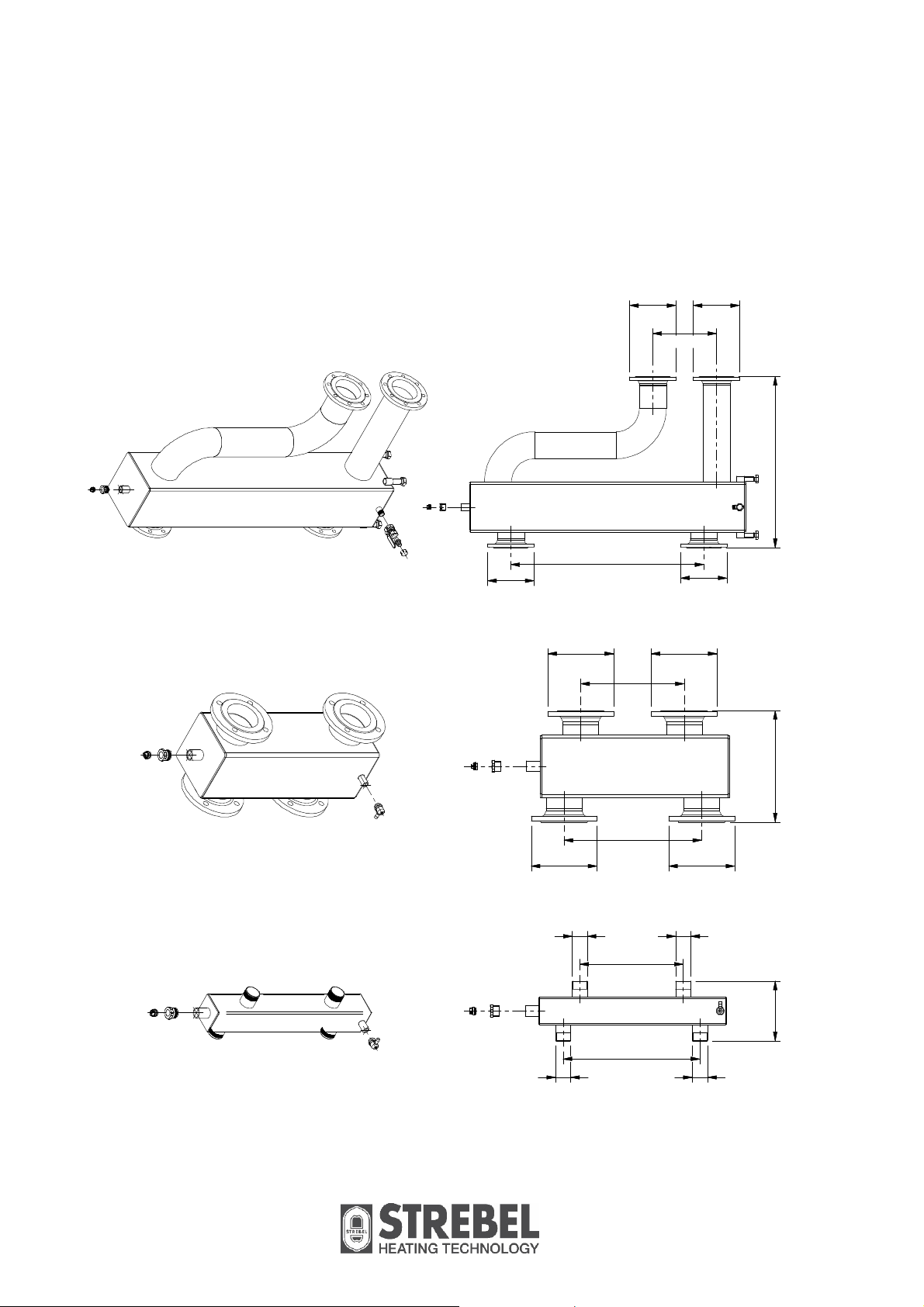
9. Low Loss Headers
The low loss header can be mounted on the right-hand or the left-hand side of the flow and return
headers, whatever is the best place to connect the headers to the heating installation.
The opposite end of the flow and return headers must be blocked by the supplied caps or flanges.
D
D
1
H
L
2
H
D
D
1
H
2
H
D
D
1
H
D
D
D
D
L L
2
H
D
D
Fig. 8.1 Fig. 8.2 Fig. 8.3
Figure 8. Low velocity headers.
22
Page 23

00
000
03
00
000
66
00
000
6
r
00
000
65
00
000
66
00
000
6
00
000
65
.1
.
Fig. 8.2
4 Boilers:
E
.1
.
Fig. 8.2
3 Boilers:
E
.
Fig. 8.3
E04.015.066
E
5 or 6 Boilers
E04.008.034
DN 125 PN 6 (5")
330
887
1000
7
.1
.2
330
439
330
440
290
E04.015.066
E04.008.025
DN 80 PN6 (3")
.
4 Boilers
Fig. 8.2
E
E04.015.066
E04.008.025
DN 100 PN6 (4")
355
.1
330
487
265
E04.015.066
E04.008.025
.
3 Boilers
Fig. 8.2
E
E04.015.066
E04.008.025
DN 65 PN6 (2½")
330
440
290
DN 80 PN6 (3")
4
.1
330
436
.
Fig. 8.1
2 Boilers:
Boilers 60 – 120
+
Low Loss Headers for S-CB
E
Header Group
Drawing
E04.015.066
1
Venting valve ½"
R 1½"
E04.008.025
Drain valve ½"
D
H1 (boiler-side)
190
Boilers 150 – 180
+
H2 (installation-side)
L
Low Loss Header for S-CB
.1
.
Header Group
Fig. 8.2
E
Drawing
2 Boilers
E04.015.066
Venting valve ½" 1 Drain valve ½"
330
487
265
E04.008.025
DN 65 PN6 (2½")
We standard supply a manual venting valve that can be mounted on top of the low loss header to manually bleed the ai
D
H1 (boiler side)
H2 (installation side)
L
Table 4. Low velocity headers.
from the low loss header. Instead of the ½” manual bleed valve, an automatic air vent can be installed, up to 1”max.
*****
23
Page 24

10. Flue gas and air supply
10.1 Individual or common flue systems
The Strebel S-CB +/ PX 120 cascade sets can be equipped with individual or common flue systems.
Using separate flue systems is always preferred above common flue systems. Only when separate flue
systems can’t be used, one should choose to use a common flue system.
When chosen for an individual flue system each boiler has its individual flue gas outlet and air supply lines to
the outside of the building. This may be executed in parallel or concentric flue gas and air supply pipes.
When chosen for a common flue system this must be executed in parallel flue gas and air supply pipes.
10.2 Individual flue systems
Individual flue systems can be chosen as mentioned in the S-CB+ instruction manual.
The flue system should comply with the chapter “Flue gas and air supply system” of the Strebel
+
S-CB
/ S-CB PX manual.
For each boiler, the combined resistance of the individual flue gas and air inlet pipe can be calculated and
checked with the maximum for the gas-side resistance.
Resistance table and example calculations are given in the same forementioned chapter of the S-CB
manual.
Please note: Using this kit does not determine the spacings between exhaust terminals and air intake
terminals.
Please refer to the relevant British Standards:
BS 6644 – Installation of gas fired hot water boilers of rated inputs between 70kW – 1.8MW.
Please refer to the Instition of Gas Engineers and Manager Documents (IGEM):
IGEM/UP/10 Edition 4 – Installation of gas fired hot water boilers of rated inputs between 70kW – 20MW.
+
10.3 Common flue systems
Common flue systems must be designed according to:
EN 13384-2 “Chimney – Thermal and fluid dynamic calculation methods – Part 2: Chimneys serving more
than one heating appliance.”
Strebel Ltd Technical can advise on what software can be used for doing these calculations. Do not attempt
to design common vent systems without the appropriate software and training.
For common flue gas systems, the parameter P5DB has to be adjusted to prevent recirculation of flue gases.
24
Page 25
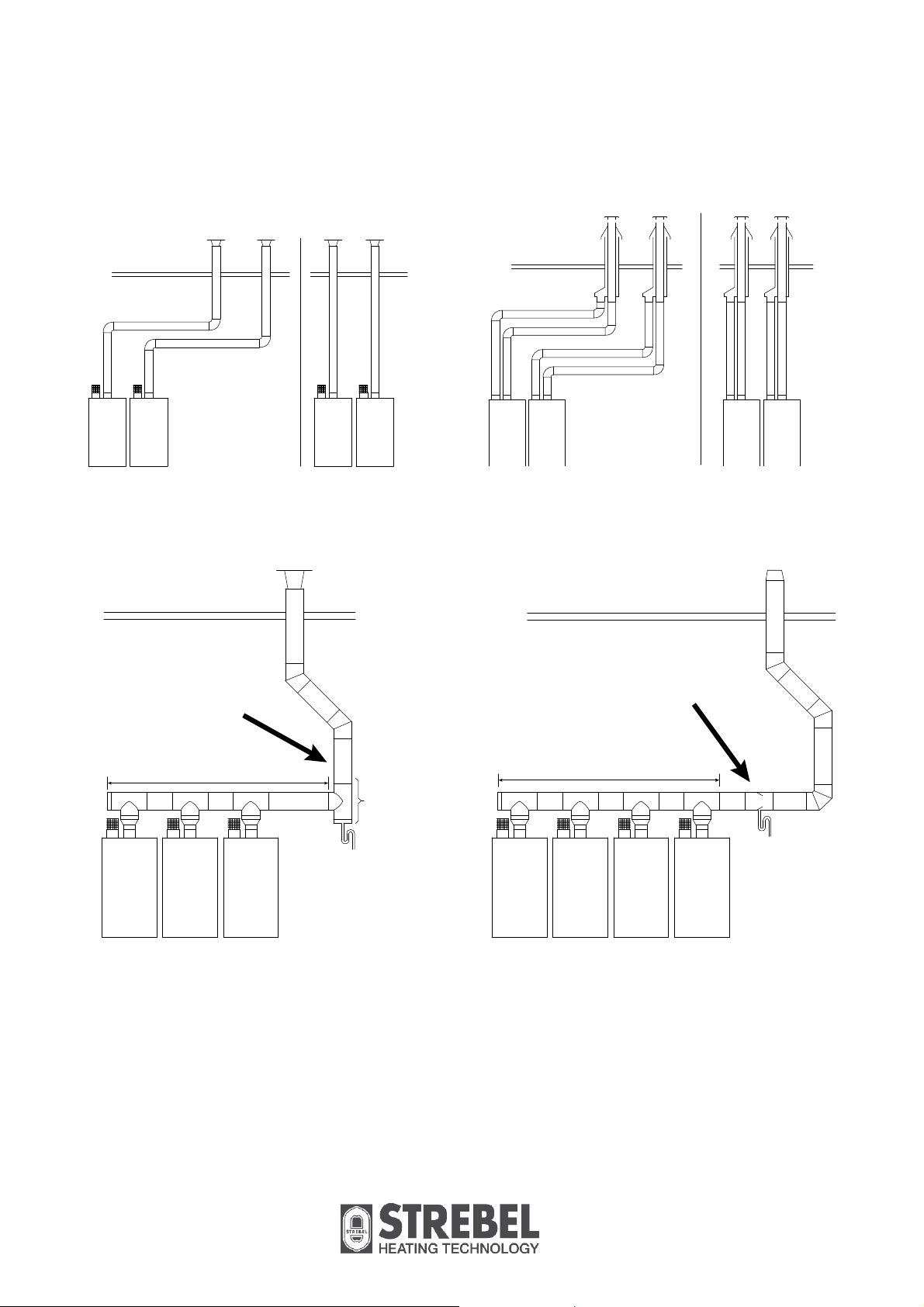
10.4 Installation examples flue gas systems.
Figure 9. Examples of separate / individual flue systems.
Condensate flowing back
from the flue gas piping
must always be drained
before reaching the
common flue header
above the boilers.
Common flue header
Condensate
Condensate flowing back
from the flue gas piping
must always be drained
before reaching the
common flue header
above the boilers.
Common flue header
Figure 10. Examples of common flue systems.
25
Page 26

11. Installation
Complete the installation with all necessary parts, valves, non-return valves, strainers, air separators and
expansion vessel, and connect the low velocity header to the heating installation (see hydraulic examples).
Mount the flue gas and air supply lines according to the recommendations of the S-CB+ / S-CB PX 120
manual and the recommendations in chapter 10. “Flue gas and air supply” of this manual.
Complete all wiring of the boilers according to the boiler manual.
First the “Master” boiler has to be determined. Connect all wiring of thermostat, outside temperature sensor,
flow temperature sensor and eventually system pump to the Master.
Also, a two-wire cable has to be connected between all boilers (cascade-connection).
Fill the installation with water and follow all recommendations of the S-CB+ manual. Insulate all water piping
as far as necessary.
In the following, two installation examples are given.
OUTDOOR SENSOR
BOILER BOILER
P1 P1
VALVE
AIR SEPARATOR
DIRT SEPARATOR
LOW LOSS
HEADER
STRAINER
(WATER FILTER)
PRESSURE RELIEF VALVE
SIPHON
S3
PUMP
AUTOMATIC AIR
VENT
EXPANSION
VESSEL
NON RETURN VALVE
(low resistance type)
NOT SPRING LOADED
HEATING
P3
Figure 11. Hydraulic example, heating only. NB! For S-CB PX 120 boilers, P1 is an external pump.
ZONE
26
Page 27

OUTDOOR SENSOR
BOILER BOILER
P1 P1
HEATING
ZONE
S3
P3
P2
INDIRECT
WATER TANK
VALVE
AIR SEPARATOR
DIRT SEPARATOR
LOW LOSS
HEADER
STRAINER
(WATER FILTER)
PRESSURE RELIEF VALVE
SIPHON
PUMP
AUTOMATIC AIR
VENT
EXPANSION
VESSEL
NON RETURN VALVE
(low resistance type)
NOT SPRING LOADED
Figure 12. Hydraulic example, heating and indirect domestic hot water. NB! For S-CB PX120 boilers, P1 is an
external pump.
Parameter change is needed. Set parameter C3 (P5DC) to “0”’ (default = “1”). See Chapter 12.3 for setting
procedure.
IMPORTANT NOTE:
The hydraulic piping of the Strebel cascade systems already contains non-return valves underneath each
boiler. When other hydraulic systems are used, non-return valves must be fitted in the return pipe of each
boiler.
27
Page 28

12. Parameters
Before commissioning the cascade installation, a number of parameters has to be changed.
These parameters can be programmed on the unit itself, without the use of a computer.
Changes in parameter may only be carried out by a skilled commissioning/service engineer, who has had
specific training for setting up the S-CB+ / S-CB PX 120 range boilers. He will be able to check whether the
installation functions correctly after the parameter change has been done.
For programming, all parameters of the boilers one needs to have an interface cable for connecting the
laptop to the boiler control and a laptop with the appropriate S-CB
+
software. This software is used for
programming but also shows all measured temperatures and cascade behaviour during operation and
service/fault history.
12.1 Parameter settings for cascaded boilers
Before programming the cascaded boilers, make sure that all boilers are connected (wire) with each other.
Use connection 17 and 18 of each boiler on S-CB+ boilers – Use connection 15 and 16 on S-CB PX 120.
Remind: Do not alternate these connections, so always connect 17 to 17 and 18 to 18 on the S-CB+ version
and 15 to 15 and 16 to 16 on the PX 120.
After connection, every boiler must be programmed as follows:
Figure 13. Parameters.
28
Page 29

12.2 Control panel / display unit
CONTROL PANEL
2 rows/ each 20 characters
DISPLAY
ON/OFF
RESET
ENTER
MENU
COMM.
PORT
ON/OFF
RESET
ENTER
SERVICE
COMM.
PORT
MENU
Press and hold for 6 seconds to switch boiler on/off.
Is also used as RESET button and ENTER button when
programming.
Connector for connecting computer cable.
Buttons can be pushed to open menu.
Buttons to toggle through measured temperatures.
Also used for navigating through the menus and for changing values.
Button to activate service function
(hold for 3 seconds).
SERVICE
Schornsteinfeger function (only for Germany).
Light: lights when controller detects good flame signal.
Lights when burner is burning.
29
Page 30

12.3 Setting the parameters using the control panel
Programming of the boiler cascade can be done using the control panel. Press the [MENU] button and select
the [PARAMETER] menu. See graphics below.
Operating screen:
H E A T I N G : S T A N D - B Y
> > > : 1 2 3 . 4 ° C ( 1 2 3 . 4 ° C )
Press [MENU]
Main menu screen:
M a i n M e n u
S e t p o i n t s
Select "Parameter" using [◄] & [►] and press [ENTER]
After this use the following password “4153”.
Parameter menu:
I n s t a l l e r c o d e
0 0 0 0
Enter the 4-digit code with the [◄] & [►] and the
[▲] & [▼] buttons and select [ENTER]
The code will blink a few seconds and when entered
correctly, the following parameters will be displayed.
Now for every single boiler of the cascade the following two parameters must be selected and programmed
according to the above drawing.
Master:
C5 P5 DF 1
C2 P5 DA 0
Slave 1:
C5 P5 DF 0
C2 P5 DA 1
Slave 2:
C5 P5 DF 0
C2 P5 DA 2
And so on.
When the correct parameter is set, this must be confirmed at the confirmation screen. After activation, the
value will blink for a few seconds while the parameter is programmed into the boiler.
Menu C: Cascade
C 5 C a s S i / M a
0
Function for the cascading of the boiler(s).
This parameter sets the function of the boiler at a
cascade alignment
0 = Single / Slave unit
1 = Master unit
Menu C: Cascade
C 2 B u s a d d r e s s
0
Function for the cascading of the boiler(s).
This parameter determines the address of the boiler
for the total cascading control.
Master = 0, Slave1 = 1, etc.
30
Page 31

When cascade connection is programmed correctly the boiler display will show the following.
Explanation "Cascade communication indicator"
NO CASCADE COMMUNICATION
> > >
no.1
Always showing the fixed ">>>"
CORRECT CASCADE COMMUNICATION
> >
>
no.1
no.2
Showing alternating no.1 & no.2 with 1 second interval.
12.4 Monitor screens
During normal operation and stand-by, the “◄” and “►” buttons can be used to show some boiler
information, including measured temperatures, settings and data. In the following graphs is explained which
cascade information (screen 11 +12) can be shown in the display.
When no button is activated for 2 minutes the display will return to its status display.
Pressing [◄] or [►] while being at the "operating screen" toggles through the screens below.
When pressing [ON/OFF, RESET, ENTER] or [MENU] at any time the display returns to the base menu.
SCREEN 11
C a s c D e s i g n 0
C a s I n f 0 1 2 3 4 5 6 7 8 9 A B
SCREEN 12
C a s c P o w e r 9 9 9 % 9 9 9 %
D u a l
DESCRIPTION "CASCINFO" Screen 11
B u r n e r :
N o
Shows the number of boilers connected with the Cascade. The Master/Lead boiler is designated as 0.
Slave/Lag boilers will be designated 1, 2, 3, 4, 5, 6, 7, 8, 9, A, B. When a “-“is used instead of a number, than
that boiler is either not connected, or in a lockout mode and not available for the Cascade. When an “x“ is
used instead of a number, than that boiler is connected, but in lockout mode.
When a “d” is used instead of a number, than that boiler is handling a DHW demand.
When the number is flashing, then that boiler is providing heat to the cascade. When the leading boiler is
changed according to the set priority change time, than that boiler’s address will be shown first in the row of
numbers.
Example 1: "3 4 5 - - - - - - 0 1 2"
There are six boilers present and nr. 3 has priority.
Example 2: "3 4 x - - - - - - d 1 2"
There are six boilers present and nr. 3 has priority. Boiler 0 is heating up an indirect DHW tank. Boiler 5 is
present, but in a lock-out.
0 = MASTER, 1 ..... 11 = SLAVES
Displays number, priority and state of cascade boilers.
% heat demand of total (cascade) power availabe (%).
One heat exchanger equipped with two burners: "Yes" or
"No".
31
Page 32

13. Cascade control
13.1 Output control
The total cascade set-up will act as one single big boiler, switching on- and off boilers, depending on the total
load necessary to adjust and keep the flow temperature at the calculated value.
When the heat demand rises, more boilers are switched on, and when heat demand falls, one or more
boilers will be switched off. The boiler that was switched on last, will be switched off first (see table below).
13.2 Boiler sequence
To distribute operating hours equally over all boilers, the working sequence of the boilers will change every
two hours.
Hour Switching ON sequence Switching OFF sequence
X
X+1
X+2
X+3
Master – Slave 1 – Slave 2 – Slave 3 –
Slave 4 – Slave 5 – Slave 6 – Slave 7
Slave 7 – Master – Slave 1 – Slave 2 –
Slave 3 – Slave 4 – Slave 5 – Slave 6
Slave 6 – Slave 7 – Master – Slave 1 –
Slave 2 – Slave 3 – Slave 4 – Slave 5
Slave 5 – Slave 6 – Slave 7 – Master –
Slave 1 – Slave 2 – Slave 3 – Slave 4
Slave 7 – Slave 6 – Slave 5 – Slave 4 –
Slave 3 – Slave 2 – Slave 1 – Master
Slave 6 – Slave 5 – Slave 4 – Slave 3 –
Slave 2 – Slave 1 – Master – Slave 7
Slave 5 – Slave 4 – Slave 3 – Slave 2 –
Slave 1 – Master – Slave 7 – Slave 6
Slave 4 – Slave 3 – Slave 2 – Slave 1 –
Master – Slave 7 – Slave 6 – Slave 5
……….. ………………………………………………… …………………………………………………
Table 5. Boiler sequence example of an eight-boiler cascade.
In this table, a total of eight boilers (one master, seven slaves) is mentioned as an example, in practice the
maximum number in a cascade, without extra (external) control, is twelve boilers.
32
Page 33
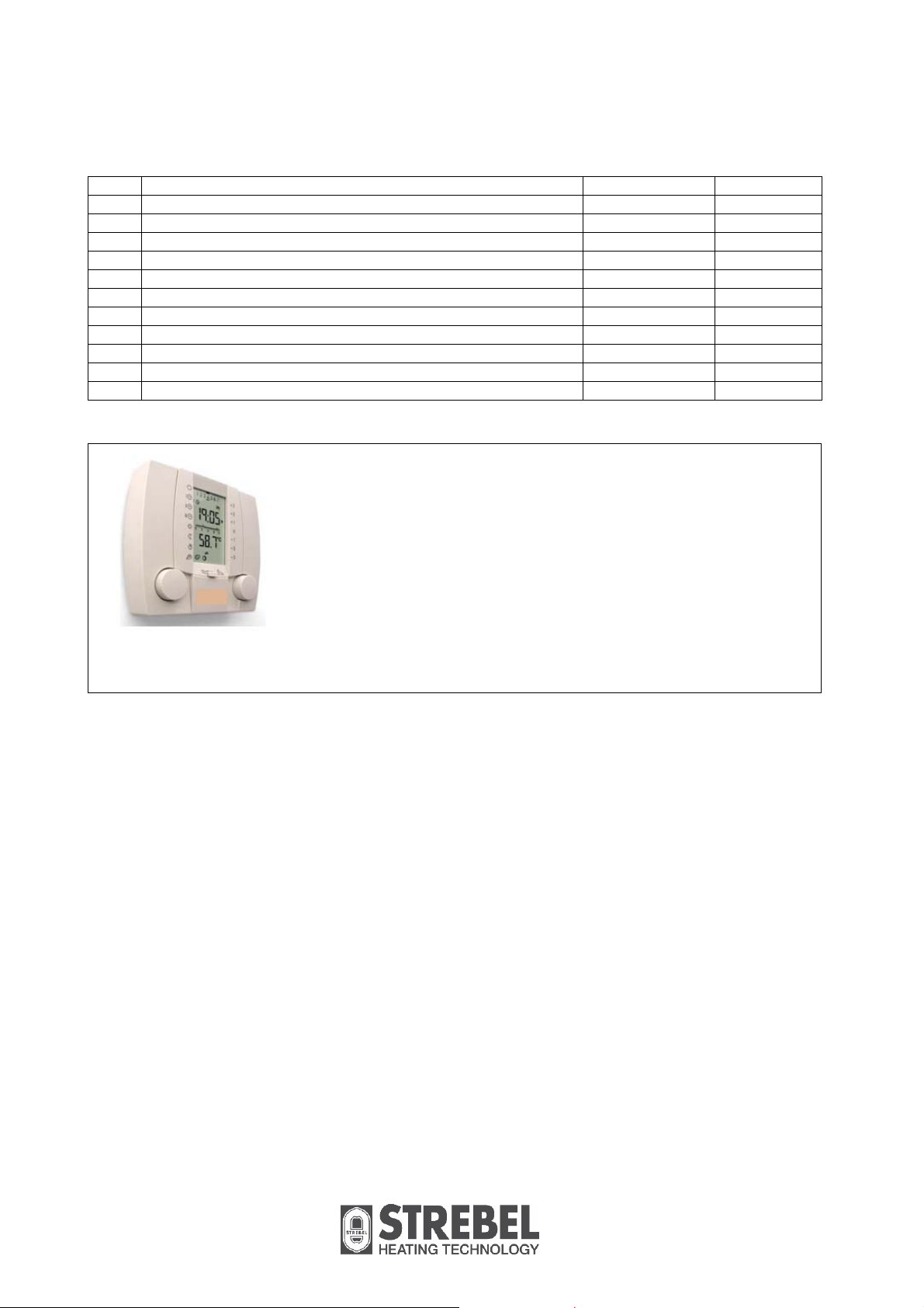
14. Options
To complete your cascade set-up / heating installation you can choose for next options:
Room Temperature Controllers
RC Open-Therm with ambient sensor Modulating S04.016.355
1
RC Open-Therm, allows for a remote ambient sensor to fit. Modulating S04.016.358
2
RCH E-bus with ambient sensor (for EBC) Modulating S04.016.357
3
Sensors
Outside air temperature sensor 12kOhm@25°C E04.016.585
4
External flow temperature sensor low velocity header 10kOhm@25°C E04.016.304
5
External ambient sensor for RC and RCH 5kOhm@25°C E04.016.359
6
External flow temperature sensor heating circuit (zone) 5kOhm@25°C E04.016.363
7
Calorifier Temperature Sensor 10kOhm@25°C E400277
8
Parameter programming
Interface cable and software to programme the boiler E400278
8
Table 6. Accessories and parts.
RC OpenTherm room temperature controller (1 and 2)
RCH E-bus room temperature controller for EBC (3)
Figure 14..
33
Page 34

- notes -
34
Page 35

- notes -
Page 36

Strebel Ltd
Unit 10, Invincible Industrial Estate,
Invincible Road, Farnborough,
Hampshire, GU14 7QU.
T 01276 685422
F 01276 685405
I www.strebel.co.uk
Further information on our complete product range is available from our website.
CAST IRON – CONDENSING – STEEL SHELL – WATER HEATERS – RENEWABLES
FLUES – ACCESSORIES.
 Loading...