

Strebel RU 1S Series, BRU 1 Series, RU 3S Series, RU 2S Series, BRU 2 Series Installation Instructions Manual
11/07/00
BOILER INSTALLATION INSTRUCTIONS FOR RU 1S / BRU 1
RU 2S / BRU 2
RU 3S
ASSEMBLY INSTRUCTIONS
General Instructions:
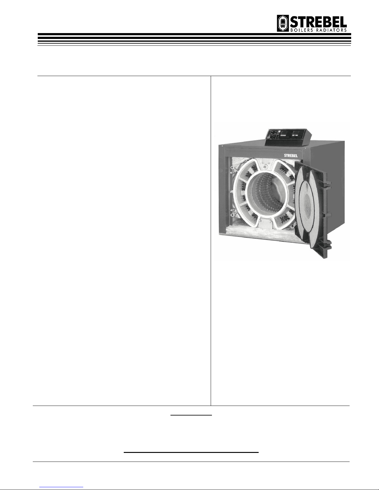
The STREBEL RU boilers are special boilers for oil or gas-fired
(forced) burners. They can be fitted in hot-water heating
installations.
Operating Conditions:
Hot-water Heating installations boiler
Maximum Heat limit Temperature 110ºC / 130ºC
Operating excess pressure normal working 4 bar
Operating excess pressure multi-storey working 6 bar
Please note all relevant instructions when assembling the boilers
The Installation: The connecting and initial setting in operation
should be carried out by a qualified heating specialist.
The boiler base is to be constructed in accordance with our
diagrams.
IMPORTANT
THERE IS A STOP NUT BETWEEN THE BOILER DOOR AND THE DOOR SEAL
(TO PROTECT THE DOOR SEAL DURING TRANSIT)
THIS NUT MUST BE REMOVED ON SITE.

ASSEMBLY INSTRUCTIONS FOR:
Page 2
11/07/00
CONTENTS:
Assembly instructions & tools
Boiler base details & Important assembly advice
Wall clearance dimensions
Pulling up sections
Pulling up sections
Positioning & Influence of baffles
Diagram of RU1 injector tube
Fitting the flue-gas collector hood
Fitting the rear wall protective refractory
Converting the burner door hinge
Assembly of boiler connections
Assembling the jackets and insulation
BRU 1s Bicalor assembly completion
BRU 1s Bicalor jacket & insulation assembly
Assembling the burner
Gas connections
Opening & closing burner door
Wiring details for control panel
RU 2s Assembly section
Fig. 1.2 through to Fig. 8.2 with corresponding notes
RU 2s Jacket assembly
RU 3s Assembly section
Fig. 1.3 through to Fig. 8.3 with corresponding notes
RU 3s Jacket assembly
Page :
3
4
5
6
7
8
9
10
10
10
11
12
13
14
15
16
17
18
22 & 23
27 & 28
ASSEMBLY INSTRUCTIONS FOR:
Page 3
11/07/00
ASSEMBLY INSTRUCTIONS
Please follow the installation instructions very carefully.
The installation of all RU and BRU boilers are very similar
through the RU 1, RU 2, RU 3, & BRU 1, & BRU 2.
For all installations please follow the instructions for the
RU1 model and, if installing the RU 2 or RU 3 models, refer
to the relevant information in the appendix at the rear of this
manual when prompted.
Information given in the appendix will allow for the
differences between models and guide installers through the
entire RU and BRU range of boilers.
ASSEMBLY TOOL
A bar pulling-up tool, which is returnable after assembly has
been successfully completed, is made available for assembling
the boiler block.
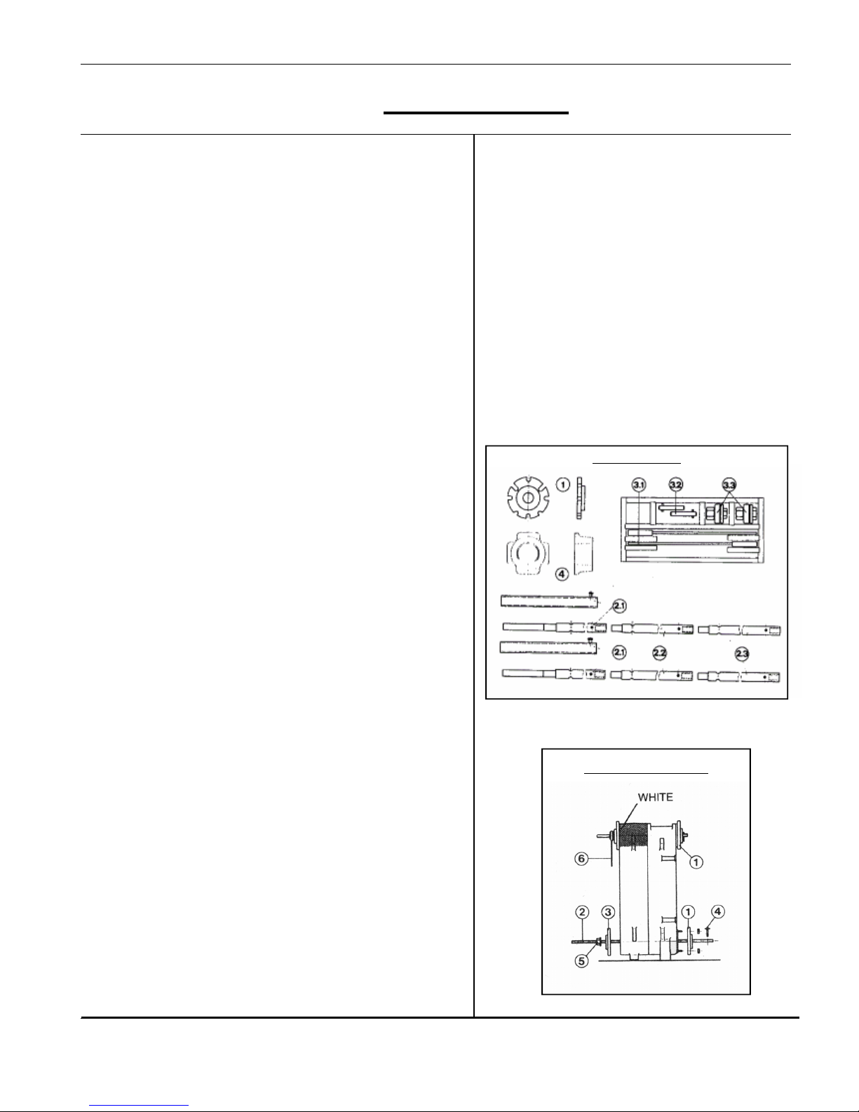
The complete pulling-up tool RU 1S consists of the following
1) Pulling-up flange for the rear, intermediate & top front section
4) Pulling-up flange at the top front section
2.1) Basic bar
2.2) Extension
2.3) End piece
3.1) Free running ratchet spanners.
3.2) Stop pins
3.3) Pulling-up nut with thrust bearing
Items needed for construction: flat chisel, mallet, brush, small
round smoothing file, emery cloth, cleanser (e.g. petroleum),
inspection lamp, spanner.
Note: RU 2s Pulling-up tools shown in Fig. 4.2 and RU 3s
tools in Fig. 8.3.
Advice on the use of the Pulling-up tool.
1) The pulling-up flanges (1) at the rear section are screwed
onto the boiler flow and return connections.
2) The basic bars (2) are inserted through the openings of the
pulling-up flanges and ports so that the screw ends are
situated out of the ports at the front. (The basic bars can be
extended, as necessary.)
3) The pulling-up flanges (1) at the intermediate section or front
section are pushed over the basic bar screw end from the
front.
4) The Stop pins (3.2) are inserted at the back through one of
the transverse borings of the pulling-up bar.
5) The pulling-up nuts (3.3) are screwed onto the basic bar
screw end, from the front until they take up the slack on the
pulling up tool flanges.
6) The free-running ratchets (3.3) are on the pulling-up nuts.
Pulling-up Tools
Using Pulling-up Tools
ASSEMBLY INSTRUCTIONS FOR:
RU 1s Assembly
ASSEMBLY INSTRUCTIONS FOR:
Page 4
11/07/00
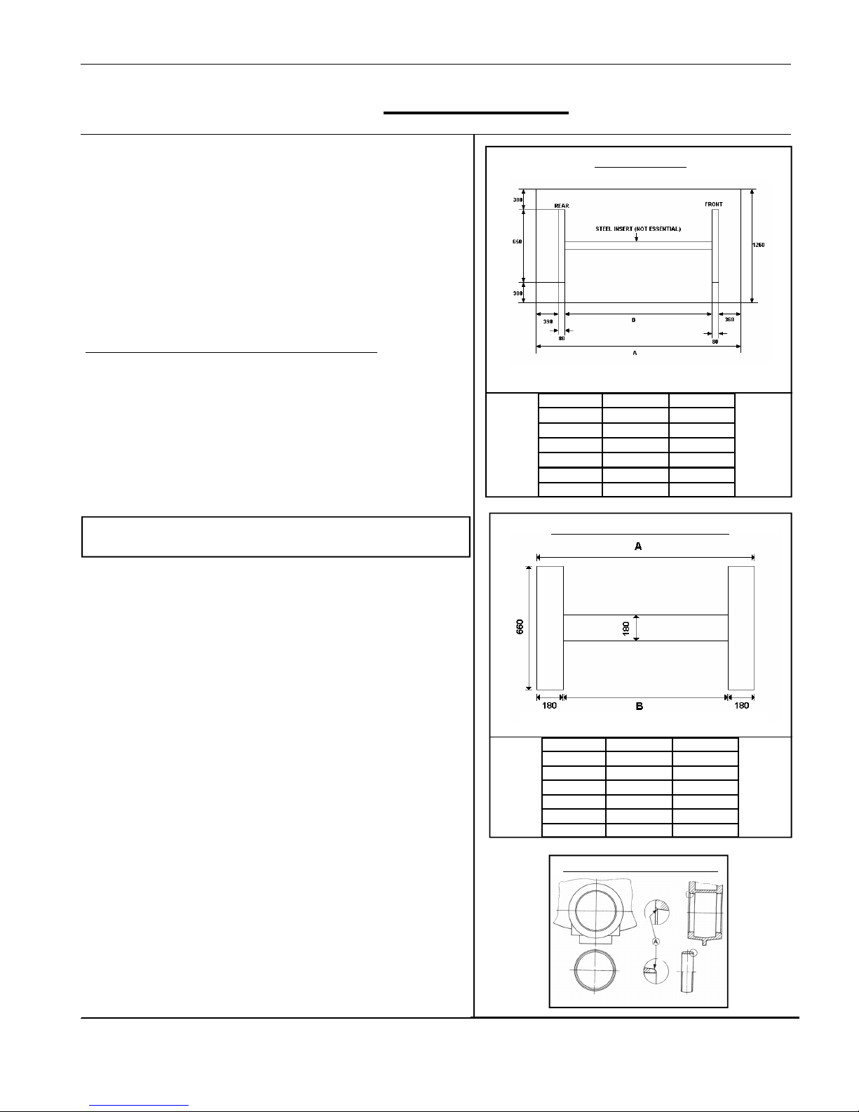
Boiler base
The boiler base is to be constructed in accordance with the base
plans. The boiler block may stand on an iron frame set in
concrete but is not essential. The boiler must stand on a level
non-combustible base which is capable of adequately supporting
the weight of the boiler, water content and any ancillary
equipment. (Dimensions for optional TICO Sound reducing
framework shown opposite). (Fig 2.2 & Fig 3.2 are for RU 2s
and Fig 2.3 & Fig 3.3 are for RU 3s).
Important Assembly Advice:
Please read through before starting the assembly!
The boiler is normally delivered in individual sections, which are
assembled on site as a boiler block using tapered nipples.
The individual weights of the boiler components are as follows:
Rear section approx. 195kg
Intermediate section approx. 185kg
Front section with burner door approx. 285kg
Front section without burner door approx. 192kg
Burner door approx. 93kg
Flue gas collection housing approx. 39kg
NOTE: Weights for RU 2s (Fig 1.2) & RU 3s (Fig 1.3) are
shown in appendix at rear.
The watertight joint between two boiler sections is a highprecision press fit between the boiler nipple and nipple port. The
block assembly must be carried out accordingly with precision.
The following points should be observed during assembly:
No damage to the nipple and borings should be apparent.
Before a nipple is inserted and a section fitted, the nipple and the
boring should be inspected. Any damage, e.g. to the face of the
boring, destroys the nipple seal and leads to leakage.
Attention! Slight damage (transport damage) to the faces of the
boiler nipple or to the nipple ports (A) can be corrected with a
small smoothing file and emery cloth without affecting the water
tightness of the joint.
− The accompanying nipple jointing oil sealing compound
serves as a lubricant as well as a waterproof seal and
must be used.
− During the assembly no dirt should be allowed to remain
on the nipples or in the boring. These should be inspected
during each assembly phase, but particularly before fixing
on the pulling-up flanges. Particles of dirt, which are not
removed, can lead to leakage.
− During the boiler block assembly take care that the various
boiler sections are fitted to the various positions,
depending on the model.
− Boiler nipples and nipple ports must align exactly at all
stages of the assembly. An inclined inserted nipple leads
to leakage.
In addition, certain specific points should be observed at each
stage.
Diagram showing nipple and boring.
Thickness of base = 60mm min.
Base Dimensions
A B
RU 1s-4 1350 440
RU 1s-5 1550 640
RU 1s-6 1750 840
RU 1s-7 1950 1040
RU 1s-8 2150 1240
RU 1s-9 2350 1440
Thickness = 20mm
TICO Sound reducing framework
A B
RU 1s-4 780 420
RU 1s-5 980 620
RU 1s-6 1180 820
RU 1s-7 1380 1020
RU 1s-8 1580 1220
RU 1s-9 1780 1420
ASSEMBLY INSTRUCTIONS FOR:
RU 1s Assembly

ASSEMBLY INSTRUCTIONS FOR:
Page 5
11/07/00
WALL CLEARANCE DIMENSIONS
KEY:
A = Boiler length + min. 200mm
B = Projection of burner + min. 100mm
ASSEMBLY INSTRUCTIONS FOR:
RU 1s Assembly

ASSEMBLY INSTRUCTIONS FOR:
Page 6
11/07/00
Stage 1: Drive nipple into nipple port with care
Inspect nipple and nipple port for damage.
Smear nipple jointing oil sealing compound over nipple and
boring. Gently drive nipple into flow and return nipple ports using
a mallet or synthetic hammer. The nipples must remain firm and
exactly vertical in the nipple ports and must be able to take the
next boiler section without twisting from nipple ports. Take care,
twisted nipples lead to leakage.
Stage 2: Before offering up the boiler section to both inserted
nipples.
Inspect nipple and nipple port for damage.
Smear nipple jointing oil sealing compound over nipple and
nipple port. Place boiler mastic sealing strand into sealing
grooves as shown in diagram opposite (see Fig. 6.2 For RU 2s
and Fig. 7.3 For RU 3s). Place boiler section in front of both
inserted nipples. Raise the boiler section onto the inserted
nipples using a flat chisel under the section feet. The inserted
nipples must stand approx. 1 to 2 mm higher than the boring of
the section, which is to be joined. Using a crowbar, raise the
boiler section onto the inserted nipples until nipple and nipple
ports mate and hold.
Inspect boring once again for any dirt deposits before fixing the
pulling-up flanges. Remove dirt deposits if necessary.
Stage 3: To assemble boiler sections using pulling-up tool.
Take care during the pulling-up process that the clearance
between both boiler and section is even. If the clearance is
uneven insert a flat chisel into the narrow point and continue
pulling-up until the clearance is even again.
Driving Nipple into Boring
Diagram showing mastic placement
Raising sections to ensure nipples and borings mate
ASSEMBLY INSTRUCTIONS FOR:
RU 1s Assembly
ASSEMBLY INSTRUCTIONS FOR:
Page 7
11/07/00
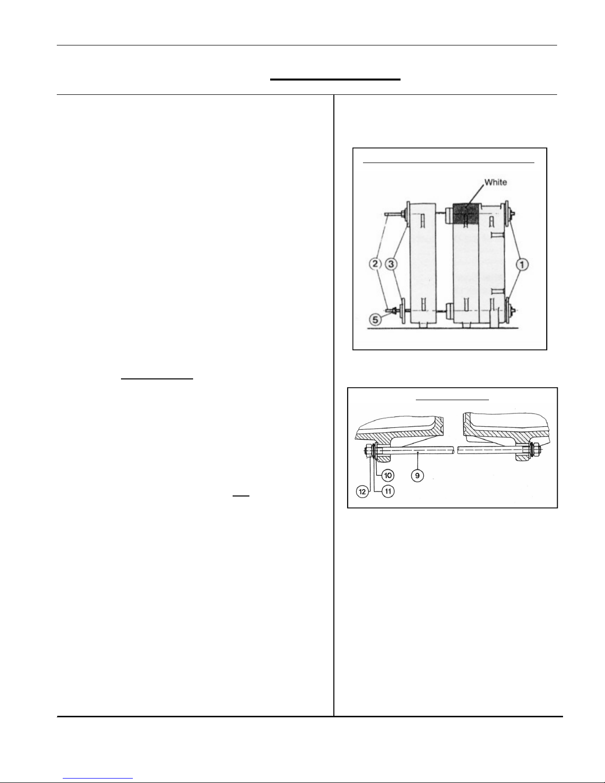
Assembly of the boiler block from individual sections
Starting with the rear section to the front, the boiler block is
assembled on the boiler base, or on the boiler base sound
reducing framework.
1: Erect and support the rear section.
2: Place boiler mastic sealing strand into the sealant grooves.
3: Clean nipple and port. Inspect and smear with nipple jointing
oil sealing compound (note assembly advice on page 4)
4: Drive nipple into flow and return ports (note assembly advice
on page 5)
5: Fix first intermediate section, marked with a white patch of
paint at the top (on RU1s only), to both rear section nipples.
(Note assembly advice on page 3)
6: Pull up intermediate section with pulling-up tool. Fix on pulling up flanges, starting nuts and free running ratchets; tighten the
starting nuts evenly. The clearance between the two sections
must be equal when pulling up. If clearance is unequal insert
a flat chisel in the narrower point and continue pulling-up
until clearance is equal again.
Avoid using excessive force.
Add on only one section at a time in each case.
Further sections (not marked with white patch) are added
accordingly.
7: Push tie bars (9) through the lugs on the ready a s s e m b l e d
boiler block. Slide a flat washer (10) and 2 disc springs (11)
with concave sides facing each other onto the tie bars at the
front and rear respectively and screw on hexagonal nut (12).
Hold fast one nut and draw on the other nut until disc springs
lie flat against each other.
After that turn back one hexagonal nut one
revolution.
RU 1S-4: 4 tie bars M 12 x 680
RU 1S-5: 4 tie bars M 12 x 880
RU 1S-6: 4 tie bars M 12 x 1080
RU 1S-7: 8 tie bars M 12 x 680
RU 1S-8: 4 tie bars M 12 x 680
And 4 tie bars M 12 x 880
RU 1S-9: 8 tie bars M 12 x 880
Boiler Block Alignment
Any unevenness between boiler base and section feet can be
levelled out by inserting metal shims underneath.
Diagram of Tie Bar
Assembling boiler block (NB: White section)
ASSEMBLY INSTRUCTIONS FOR:
RU 1s Assembly
ASSEMBLY INSTRUCTIONS FOR:
Page 8
11/07/00
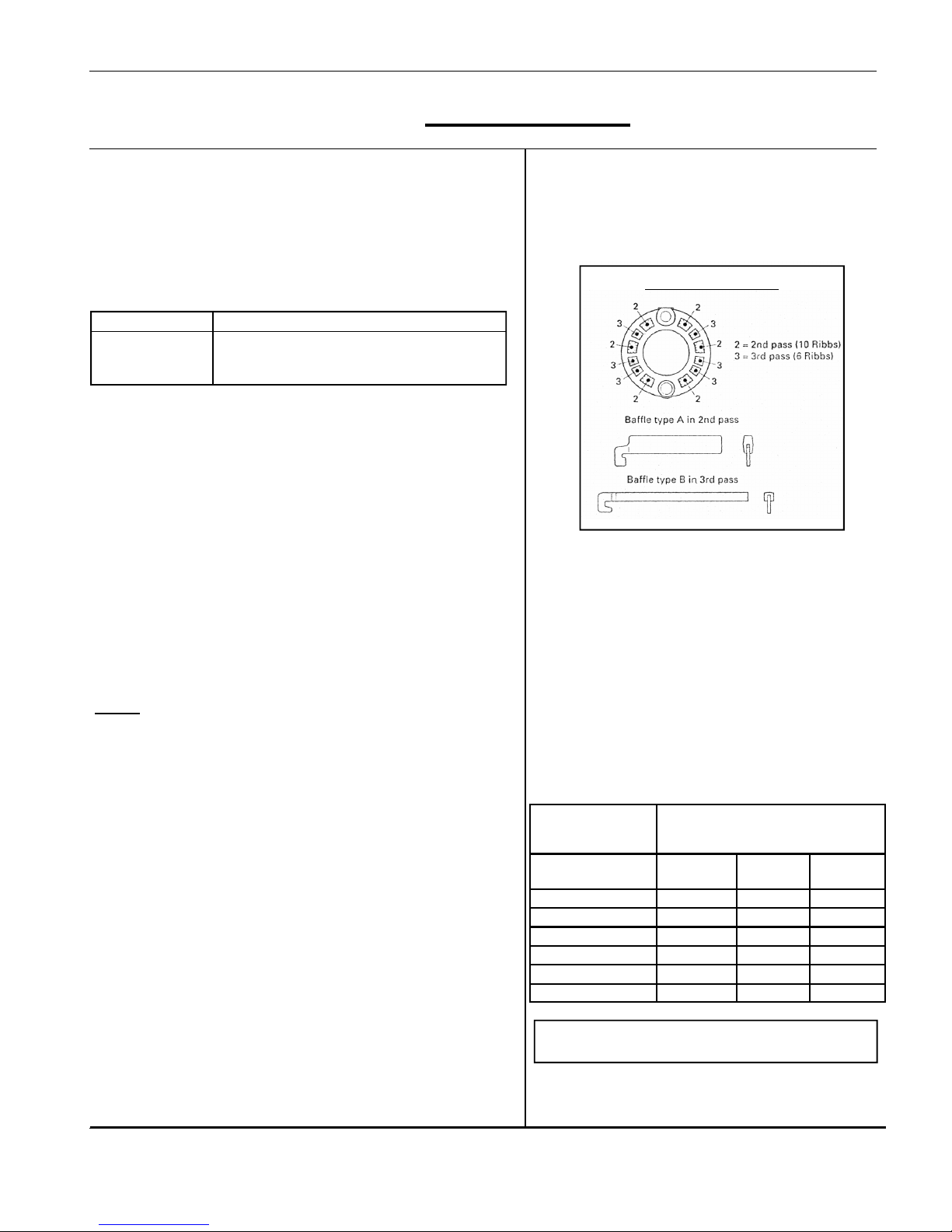
Positioning the baffles
Push the Baffles into the flue–ways as far as the stop Fit
standard equipment in accordance with table below.
Flue gas temperature can be raised by removing the baffles.
Standard boilers are equipped with the following baffles.
Boiler sections 4 5 6 7 8 9
2nd Pass 6xA 6xA 6xA 6xA 6xA 6xB
3rd Pass 6xB 6xB 4xB 4xB
With less than 6 baffles the lower passes remain free.
The flue gas temperature of a boiler depends on boiler water
temperature and boiler capacity. If boiler water temperature is
reduced the flue gas temperature is also reduced. If boiler
capacity is reduced by means of a different burner setting or by
the first stage of a two-stage burner, the flue gas temperature is
also reduced. The flue gas temperature rises by some 20ºC –
40ºC in the case of dirty flue-way surfaces, depending on the
degree of fouling.
Influence of baffles
If the baffles in the 3rd flue pass are removed, the flue gas
temperature rises by approx. 20ºC; if the baffles in the 2nd flue
pass are also removed, the flue gas temperature rises by a total
of approx. 40ºC.
NOTE:
RU 2s baffle details in Fig 8.2.
The RU 3s range of boilers do NOT use flue gas baffles.
Alternatively they have ribbed intermediate sections
denoted by the section legs painted in green.
Influence of water temperature
A change of 10ºC in the water temperature produces a change in
flue gas temperature of approx. 5ºC– 8ºC.
Boiler water and return temperatures
The boiler is operated with low flue-gas temperatures in order to
achieve maximum efficiency. If the boiler water or return
temperatures are too low, there is a danger that heating surfaces
will become fouled and encrusted this results in higher flue gas
temperatures, making boiler cleaning difficult, and in extreme
cases cause damage.
The following conditions must be maintained:
Oil fired: boiler water temperature min: 60ºC
Return water temperature min: 50ºC
Gas fired boiler water temperature min: 70ºC
Return water temperature min: 60ºC
RU 1s max. kW oil kg/h Nat. gas
m /h
4 190 17.5 22
5 250 23 29
6 320 29.5 37
7 390 36 46
8 460 42 54
9 525 47.8 61
Type and
no. of sections
Output and fuel consumption
Refer to Fig. 7.2 for technical data on the RU 2s and
Fig. 6.3 for the RU 3s
Positioning the Baffles
ASSEMBLY INSTRUCTIONS FOR:
RU 1s Assembly
ASSEMBLY INSTRUCTIONS FOR:
Page 9
11/07/00
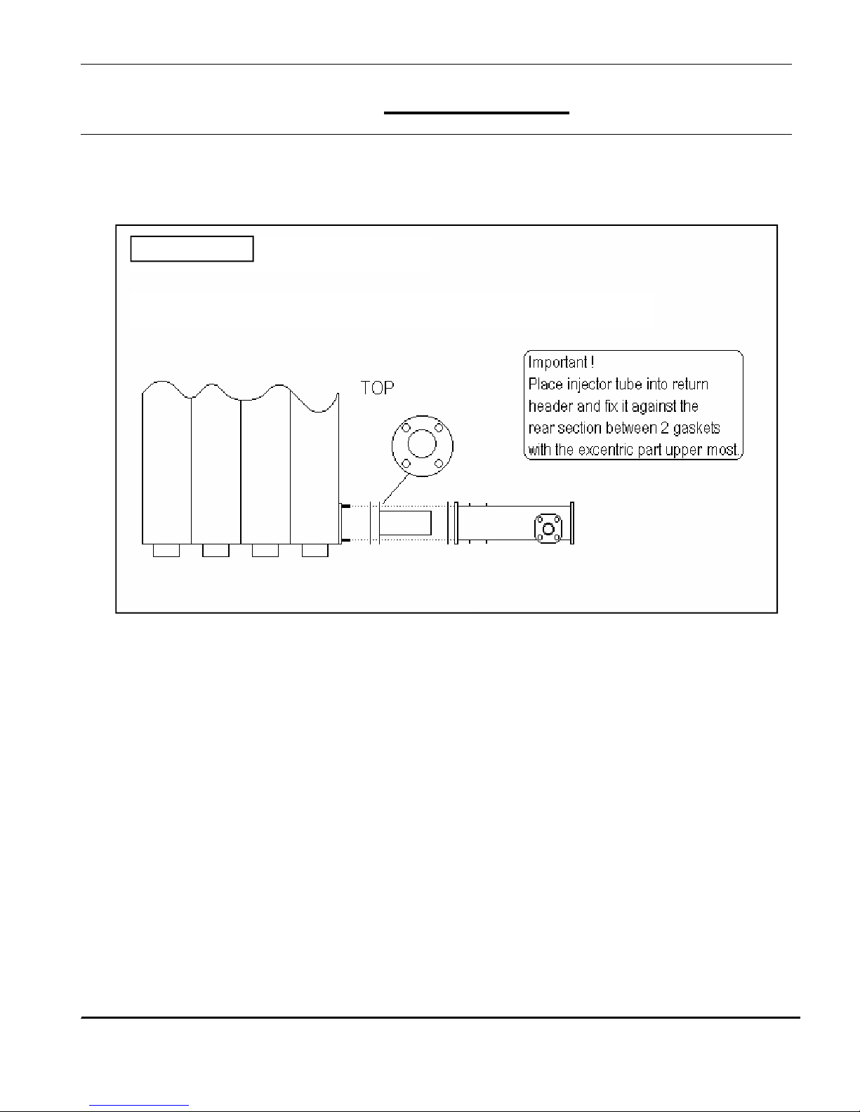
NOTE: Injector tube is not a requirement for the RU 2s and RU 3s boilers.
STREBEL RU 1s
Injector tube in the STREBEL RU 1s return
ASSEMBLY INSTRUCTIONS FOR:
RU 1s Assembly
 Loading...