

Page 1

19
STREBEL
TECHNICAL MANUAL
ML GT
ML JB
LOW NOx
CONDENSING BOILERS
Page 2

TABLE OF CONTENTS
1 GENERAL........................................................................................................................................................ 2
2 GENERAL WARNINGS..................................................................................................................................... 3
3 TECHNICAL SPECIFICATIONS .......................................................................................................................... 4
3.1 ML 45 GT – 350 GT............................................................................................................................................... 4
3.2 ML 30 JB - 670 JB ................................................................................................................................................ 6
4 INSTALLATION ............................................................................................................................................... 9
4.1 HEATING SYSTEM............................................................................................................................................... 9
4.1.1 BOILER ROOM............................................................................................................................................................. 9
4.2 FLUE..................................................................................................................................................................... 9
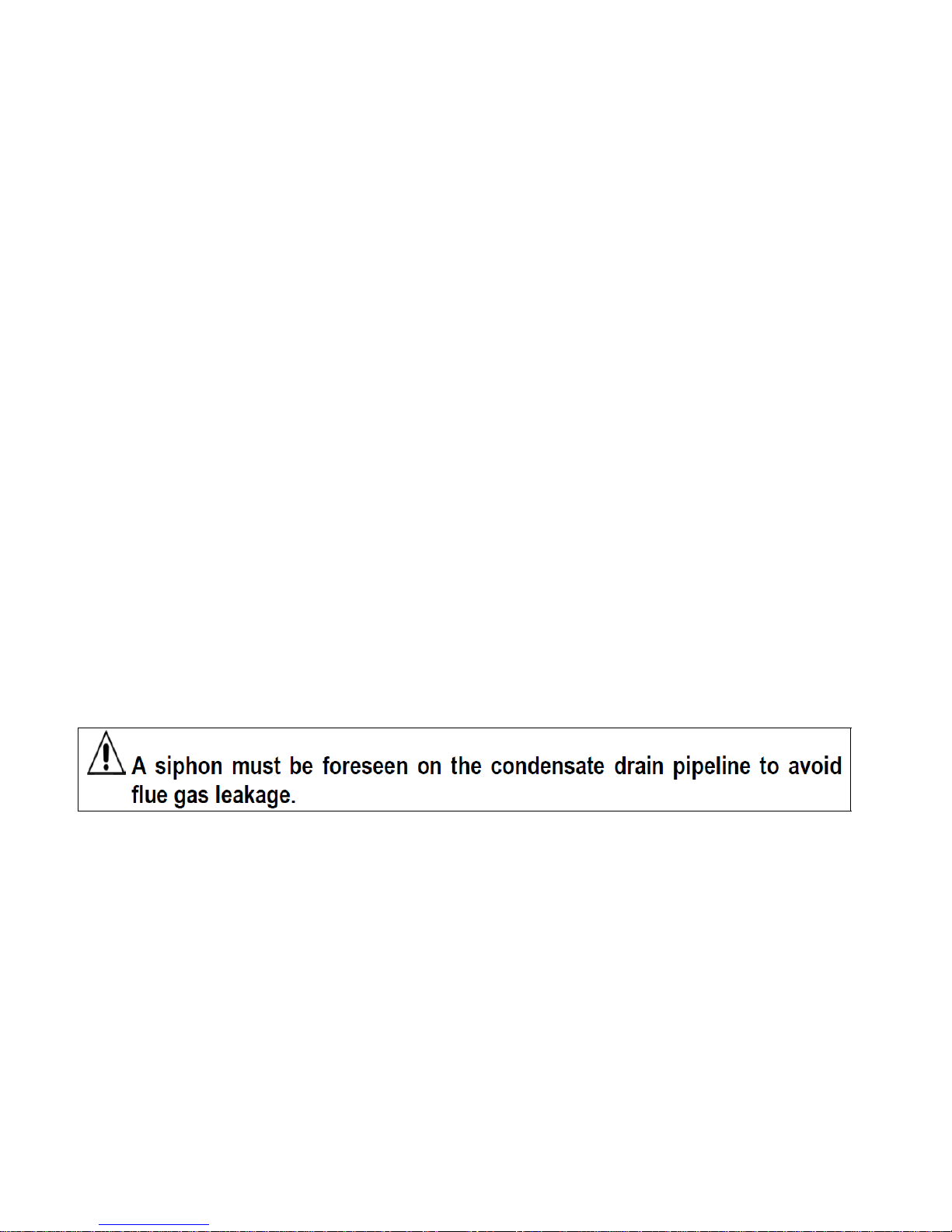
4.2.1 CONDENSATE DRAIN................................................................................................................................................. 9
4.3 WATER CONNECTIONS...................................................................................................................................... 9
4.4 ELECTRICAL CONNECTION ............................................................................................................................ 10
4.5 CONTROL PANEL......................................................................................................................................... .... 10
4.6 STARTING.......................................................................................................................................................... 10
4.7 RE HANDING THE DOOR (MOD. 45 GT/125 GT)............................................................................................. 11
4.8 RE HANDING THE DOOR (MOD. 160 GT/JB - 350 GT/670 JB) ...................................................................... 11
4.9 BOILER FUEL and AIR SUPPLY....................................................................................................................... 12
4.10 WIRING DIAGRAM........................................................................................................................................... 12
5 FITTING THE BOILER CASING........................................................................................................................ 13
5.1 BOILER BODY INSULATION ............................................................................................................................. 13
5.2 BOILER CASING MOD. 45 GT/125 GT – 30 JB/125 JB..................................................................................... 13
5.3 BOILER CASING MOD. 160 GT/JB-270 GT/JB.................................................................................................. 14
5.4 BOILER COVERING MOD. 350 GT/JB-670 JB) ................................................................................................ 15
6 STARTING.................................................................................................................................................... 16
6.1 PRELIMINARY CHECKS.................................................................................................................................... 16
6.2 WATER TREATMENT ........................................................................................................................................ 16
6.3 FILLING THE SYSTEM....................................................................................................................................... 16
7 OPERATION ................................................................................................................................................. 17
7.1 OPERATION CHECKS ...................................................................................................................................... 17
7.2 TEMPORARY BOILER STOP............................................................................................................................. 17
7.3 PROLONGED BOILER STOP ............................................................................................................................ 17
7.4 PERIODICAL USER CHECKS............................................................................................................................ 17
7.5 MAINTENANCE AND CLEANING ...................................................................................................................... 17
Page 3
2
Page 4

3
Page 5
4
ML
ML
ML
FUEL BOTH LPG AND NATURAL GAS
ACCORDING TO THE SPECIFIED BURNER
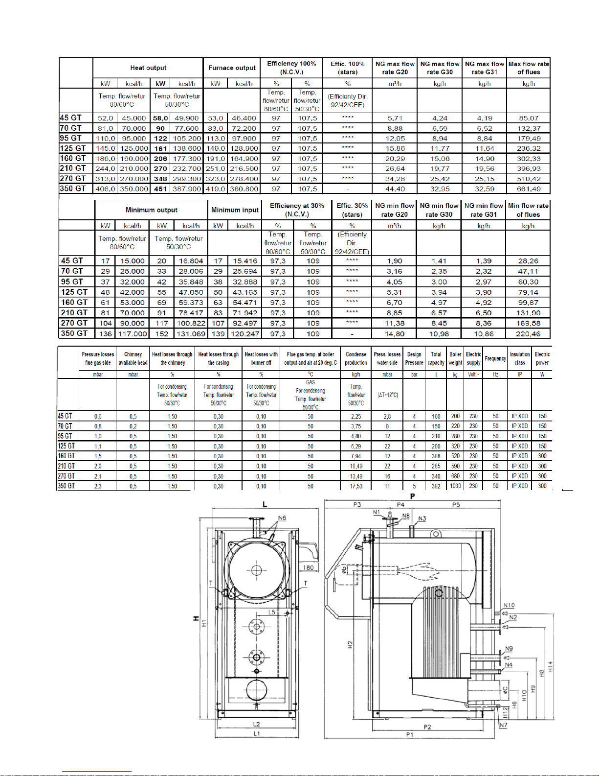
3 TECHNICAL SPECIFICATIONS
3.1 ml 45 GT—350 GT
MODEL 45 GT— 125 GT
Page 6
5
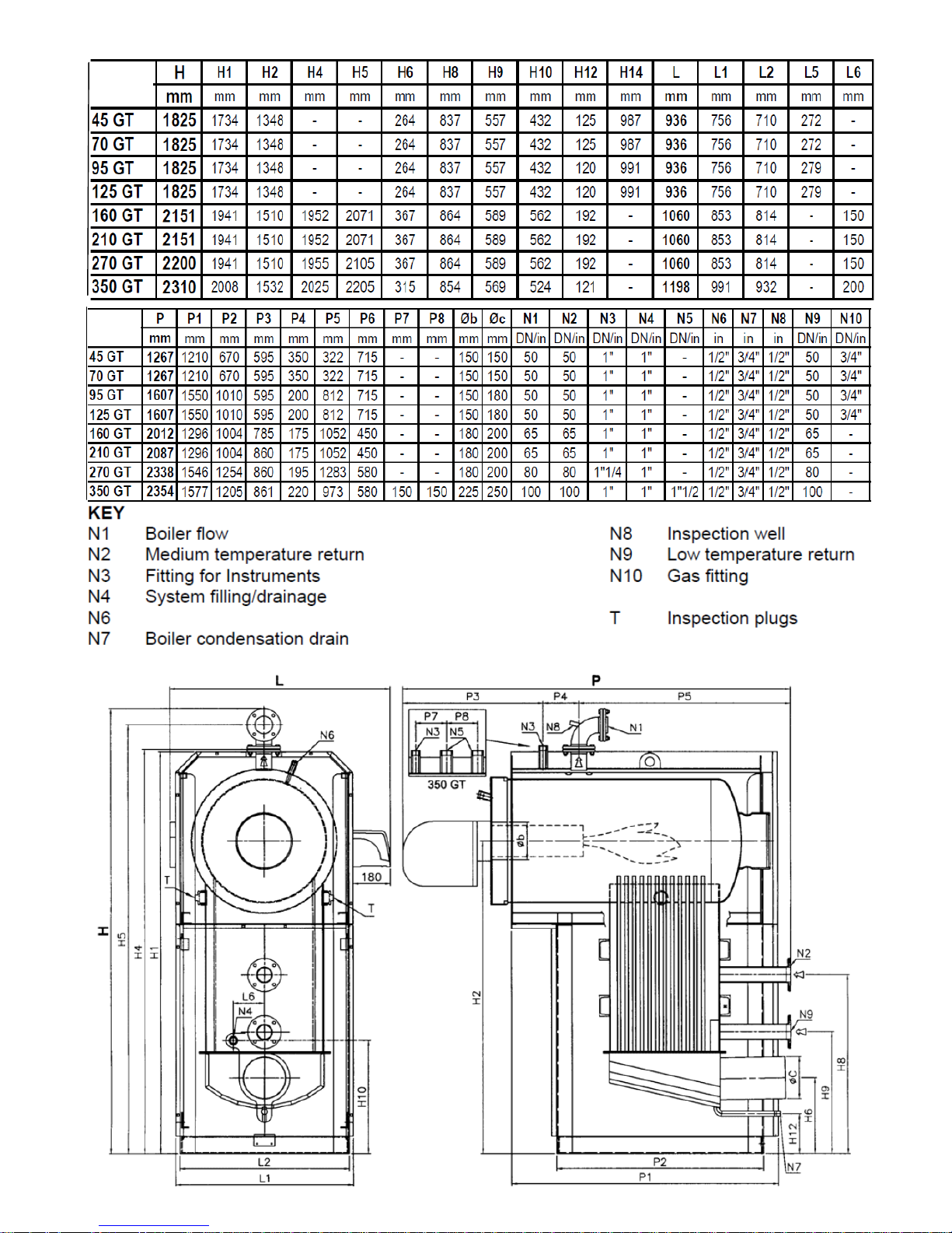
MODEL 160 GT— 350 GT (SHOWN BELOW WITH DIMENSIONS ON THE NEXT PAGE)
ML
ML
Capillary bulb pockets
Page 7
6
ML
ML
ML
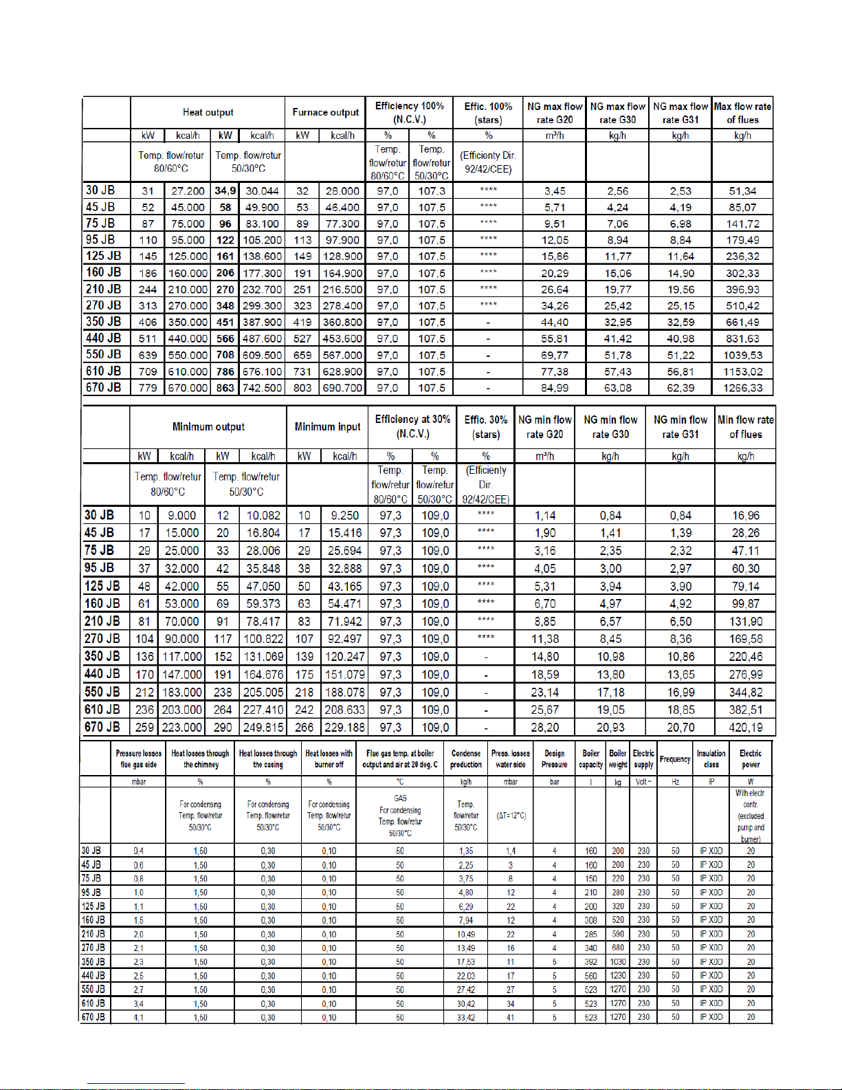
BOTH NATURAL GAS AND LPG ACCORDING TO THE BURNER SPECIFIED
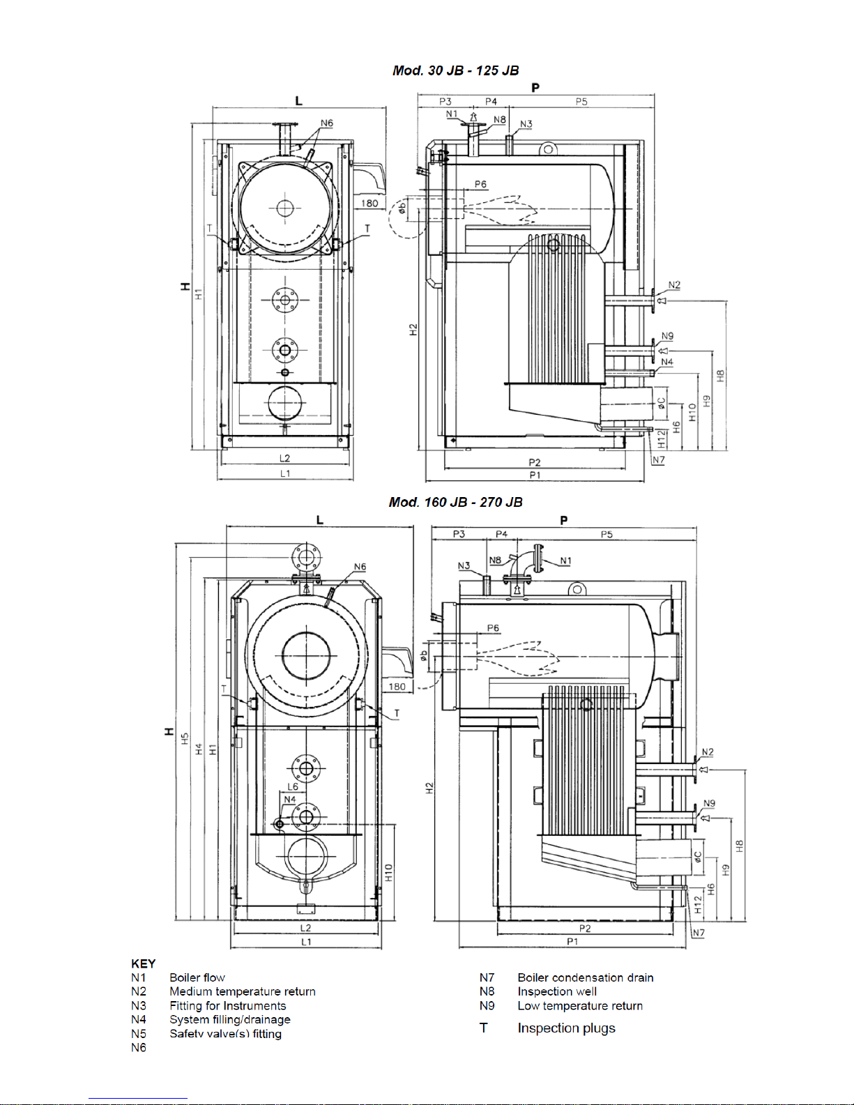
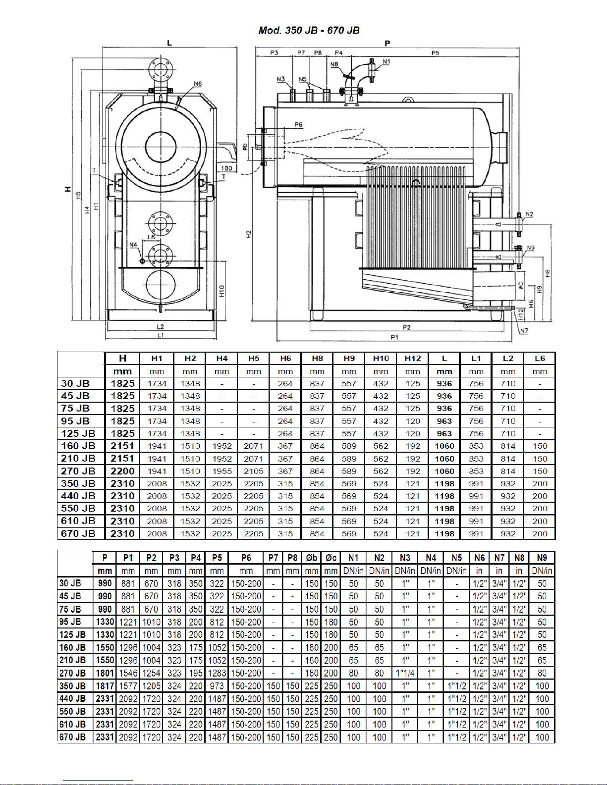
3.2 ML 30 JB—670 JB
Page 8
7
Capillary bulb pockets
Page 9
8
ML
ML
Page 10
9
4 INSTALLATION
Before connecting the boiler, carry out the following operations:
•Flush and clean carefully all the system pipework to remove any residues that could damage impede correct boiler
operation;
• Check that the flue has sufficient draught, has no restrictions, is free of all soot and residues, and is perfectly
gas tight in particular to the condensate and water vapour contained in the flue gas. Check further that no other devices are connected to the flue. Take account of applicable regulations.
4.1 HEATING SYSTEM
4.1.1 Boiler room
The system must correspond to current applicable regulations. In all cases, the boiler must be installed in
adequately ventilated rooms that also have sufficient space for routine maintenance and repair work.
4.2 FLUE
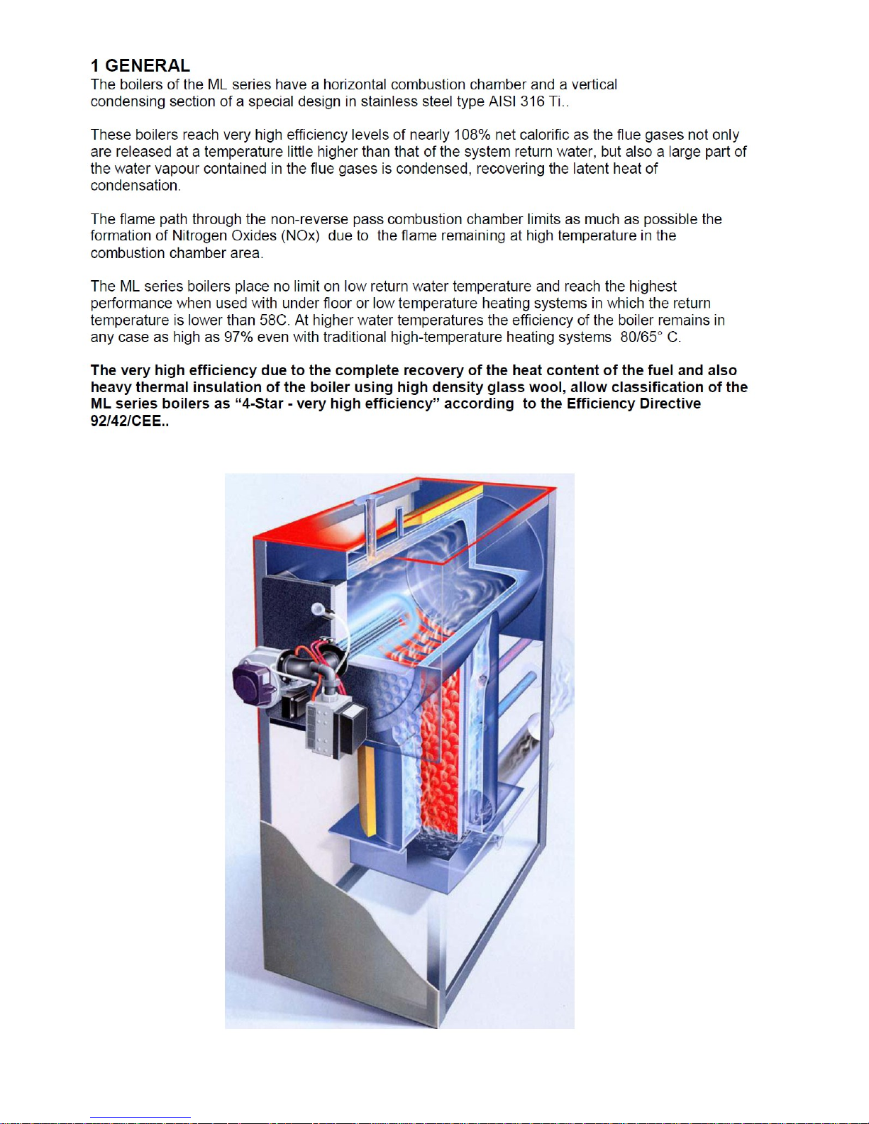
The ML boiler that is now a part of your heating system (boiler dimensions shown in this manual do not include the
burner) has a burner with a fan that supplies, to the combustion chamber, the quantity of air needed for the
fuel, at the correct pressure to move products to the chimney / flue.
The boiler flue gas connection to the chimney base must be inclined, rising in the direction of flow, with a
suggested slope not less than 10%. The path of this connection shall be as short and straight as possible,
any bends being designed taking account of the rules used in designing flues.
Chimneys must in any case be dimensioned according to Standard UNI 9615.
WARNING
The ue gas temperatures produced by ML boilers are considerably lower than non-condensing boilers, and have therefore
very high relave humidity. For these reasons the chimney must be completely waterght, stand corrosion aack by acid
condensate and must be adequately insulated to guarantee sucient draught.
4.2.1 Condensate drain
4.3 WATER CONNECTIONS
Make sure that the water pressure downstream of the water supply pressure reducer is lower than the working
pressure shown on the boiler data plate.
During operation, the water in the heating system increases in pressure; make sure therefore, that the
maximum pressure reached does not exceed the maximum admissible pressure for the boiler as shown on the boiler plate.
Make sure that the safety valve discharge fittings of the boiler and of any sanitary water heater are connected
to the drains via an open funnel, so that if the safety valves open, the boiler room will not be flooded.
Make sure that the water and heating system pipework are not used as a ground for the electrical system other than
equipotential bonding .
if so, serious damage can be caused in a short time to the boiler, pipework, water heater and radiators. Once the
heating system has been filled with water, close the water supply valve, and keep it closed. Any water leaks from
the system will then appear as pressure drops, as shown by the system pressure gauge.
Page 11
10
4.4 ELECTRICAL CONNECTION
The electrical system in a heating plant is the subject of numerous regulaons, some of which are general in character others being specic to the type of applicaon or type of fuel. Observe all regulaons
4.5 CONTROL PANEL
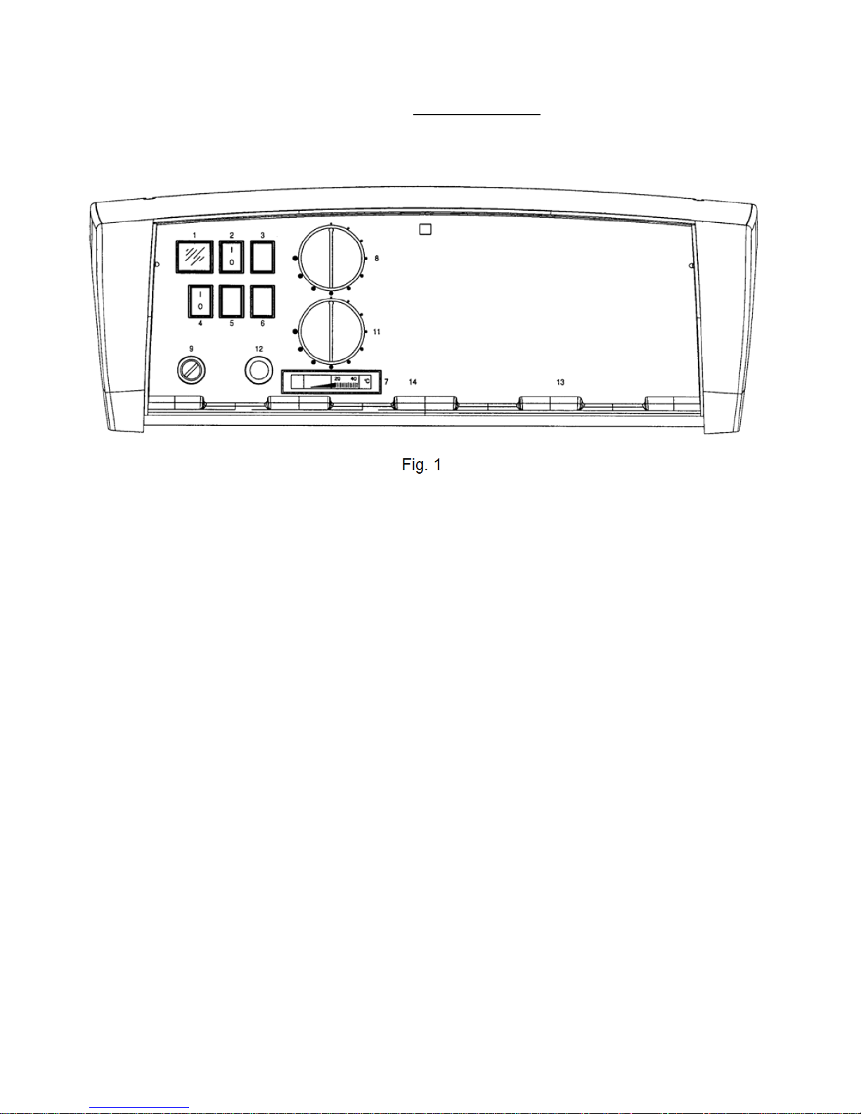
The control panel supplied with the boilers is made of self-extinguishing plastic and houses the regulation and safety
instruments:
LEGEND
1 PANEL LIVE
2 BURNER SWITCH N. 1
4 HEATING PUMP SWITCH
7 BOILER THERMOMETER
8 BOILER LIMIT THERMOSTAT
9 SAFETY LIMIT THERMOSTAT
11 2nd FLAME THERMOSTAT
The upper part of the control panel can be rotated to gain access to the terminal board and uncoil the thermostat
and thermometer capillaries. A copy of the wiring diagram is contained inside the control panel cover.
The control thermostats (TR1-TR2) have an operating range from 0° to 90° and can be set by the user by means of the
front dial.
Safety limit thermostats (TS) has a fixed setting of 100 (+0/-6)°C and can be manually reset.
For correct installation, refer to the boiler casing assembly instructions.
4.6 STARTING
Open the gas valve (check if there is any gas leakage). Switch on the burner, heating pump and the control panel.
At this point if the water temperature inside the boiler is less that the value set up on the control thermostat
and all controls are calling the burner and the pump will run.
NB. It is common to find air inside the gas pipe-work, especially during the initial start up the gas supply pipework
should be vented according to very strict regulations..
Check the all pumps are running.
CONNECTION LIVE/NEUTRAL
If the connecons of the live and the neutral are not correct the burner could stop at the end of the
safety me (even if the burner is running).
Page 12
11
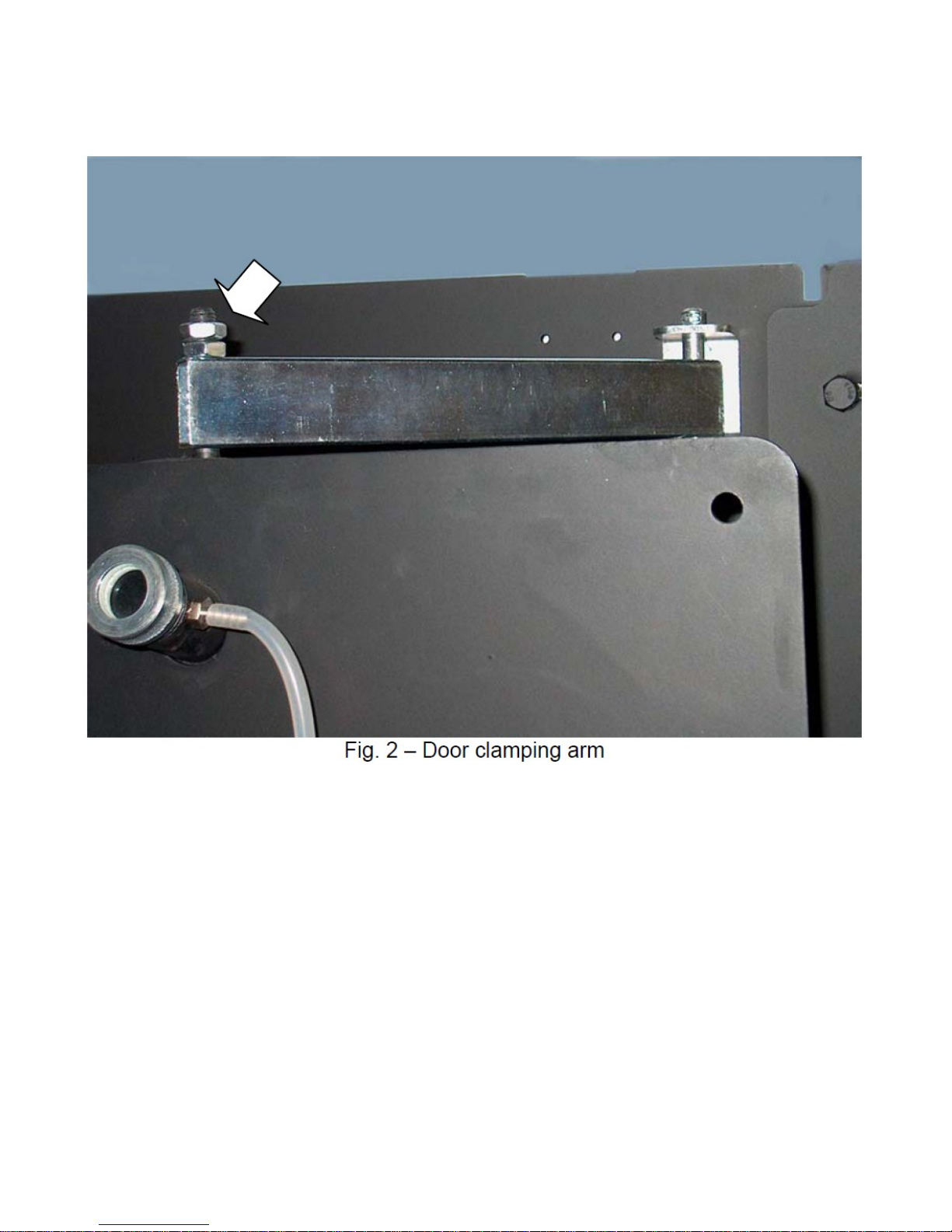
4.7 CHANGING THE DOOR OPENING RIGHT TO LEFT (MOD. 45 GT/125 GT)
The door can be opened in either direction (RH or LH). For the door height adjustment see Fig. 2.
4.8 CHANGING THE DOOR OPENING RIGHT TO LEFT (mod. 160 GT/JB - 350 GT/670 JB)
If the door is to be opened to the opposite side, proceed as folllows:
1. Switch the outside nut (or bush) of one hinge with the opposite closure bush; then at the
hinge side, fasten the cone to the door with the inside nut.
2. Repeat the operation for the other hinge.
3. For any adjustment needed, adjust the specific hinge nuts.
Page 13
12
4.9 BOILER FUEL and AIR SUPPLY
Before installation, clean the inside of all the fuel supply pipes, to remove any residues that might compromise
correct boiler operation. Check the combustion chamber pressure, as shown in the technical table.
a) check the fuel supply system for any leaks;
b) adjust the fuel supply rate to the required boiler Kw rating;
c) check that the boiler is suitable for the type of fuel supplied
d) check that the fuel supply pressure is within the values shown on the burner data plate/manual;
e) check that the fuel supply system is sized adequately for the fuel supply rate required and that the fuel supply system is complete with all the safety and control devices to meet current applicable regulations.
f) check that the gas line and hydraulics conform to current applicable standards and regulations;
g) check that all gas connections are perfectly gas-tight;
h) check that the boiler room ventilation openings comply fully to applicable regulations.
i) check that the gas pipes are not used as a ground (earth) for electrical devices.
If the boiler will not be used for some time, close the fuel supply.
BURNER MOUNTING
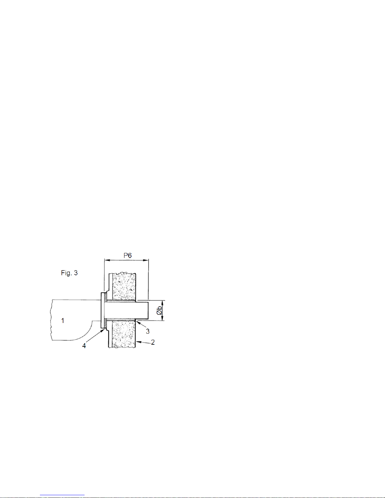
IMPORTANT: Check that the spaces between the burner sleeve and the boiler door are lled with thermal insulaon (Fig. 3). A piece of ceramic fibre insulation rope is provided with the boiler. If this is not suited to the specific
burner fitted, use a rope of a different diameter and of the same material.
KEY:
1. Burner
2. Thermal insulang material
3. Burner draught tube aperture
4. Flange
All details on the draught tube length (P6), the diameter of the burner aperture (Øb) and the combustion chamber pressure are included in the Technical Specifications.
4.10 WIRING DIAGRAM
See wiring diagram inside the boiler control panel supplied:
• Control panel with thermostats (standard)
• Control panel with RVA 43 digital controller for high/low burners (optional)
• Control panel with RVA 63 digital controller for modulating burners (optional)
REMARK: specic instrucon are provided along the digital controllers control panels.
Page 14
13
5 FITTING THE BOILER CASING
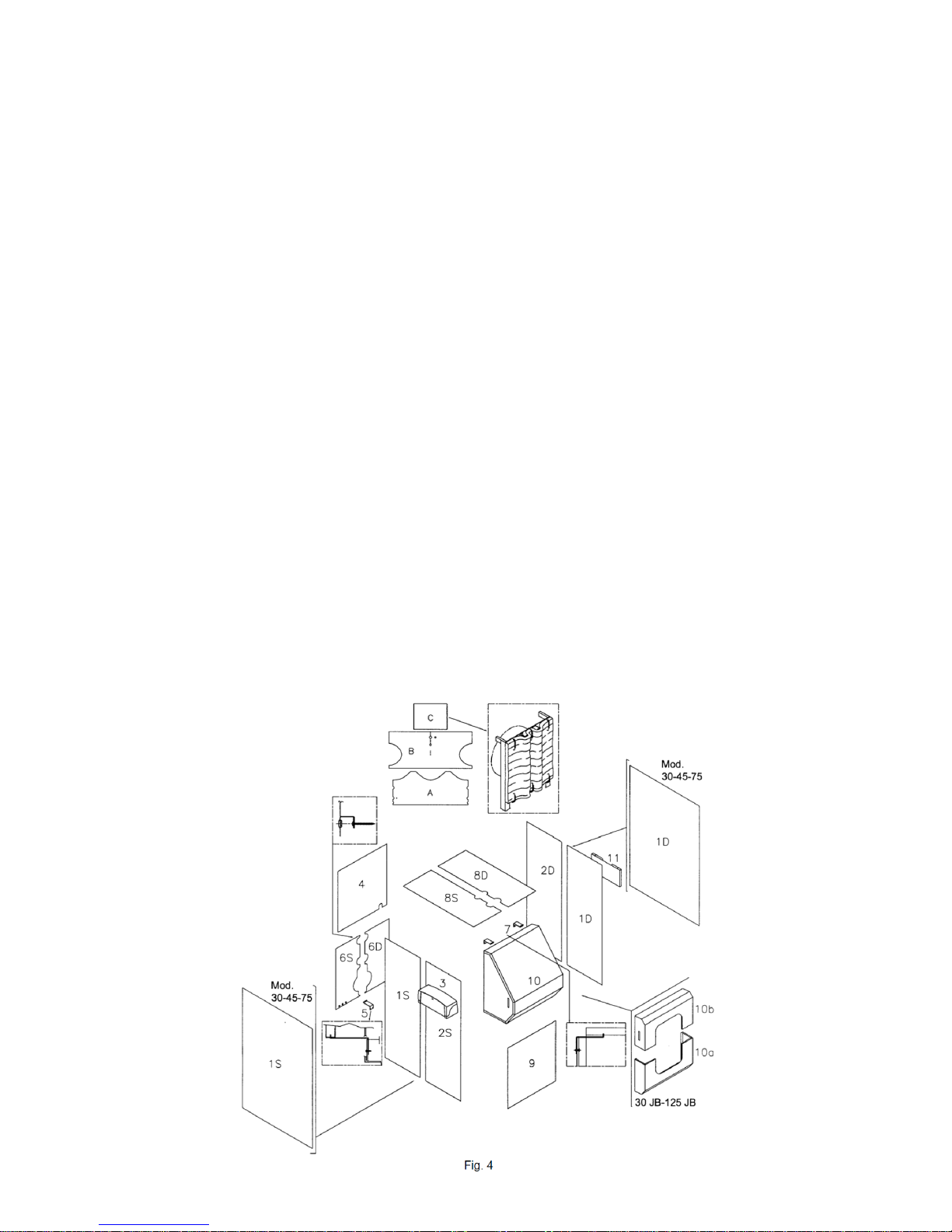
5.1 BOILER BODY INSULATION (Fig. 4-5-6)
• Wrap glass wool (A) around the column and attach with the clips.
• Wrap glass wool (B) around the upper cylindrical boiler body without covering the shaft/bulb holder located near the
flanged outlet pipe and fix in position with the clips supplied.
• Then insulate the rear boiler plate, attaching the wool (C) to the springs on the edge of the plate (see figure 4).
5.2 BOILER CASING MOD. 45 GT/125 GT – 30 JB/125 JB (Fig. 4)
• Fit the panel (1D) by hooking the upper profile to the square profile and the lower to the boiler fixing. Repeat
the same procedure for panel (1S).
• Fit the panel (2D) by hooking the upper profile to the square section and the lower to the boiler fixing
making sure that the side panels are joined by the specific coupling pins. Repeat the procedure for panel (2S) with
the burner-control panel connection cables passing through the aperture (for the wiring harness please refer to
the control panel diagram and to the standard plugs connection kit).
• Unwind the thermostat capillaries, fit the control panel (3) to the side (RH or LH), fastening with the screw,
then insert the bulbs in the boiler pockets. Hook the upper rear panel (4) to the sides.
• Fasten the support bracket (5) to the frame base L profile; insert the cable grommets in the panel holes (6S),
hook the panel to the side panel and feed through the supply cable, then connecting the cable to the junction
box. Hook on the panel (6D) and then fasten both using the screws at the top, and close the holes with the
specific plugs provided (see figure).
• Fix the front/upper panel supports (7) to the boiler plate (excluded JB) and put on the upper panels (8S) and
(8D). Hook on the front/lower panel (9) and the front/upper panel (10). For JB models, hook the front/central
panel (10a) and the front/upper panel (10b). Finally, screw the document holder (11) on to the opposite side of
the control panel (excluded mod. 30/45/75).
Page 15
14
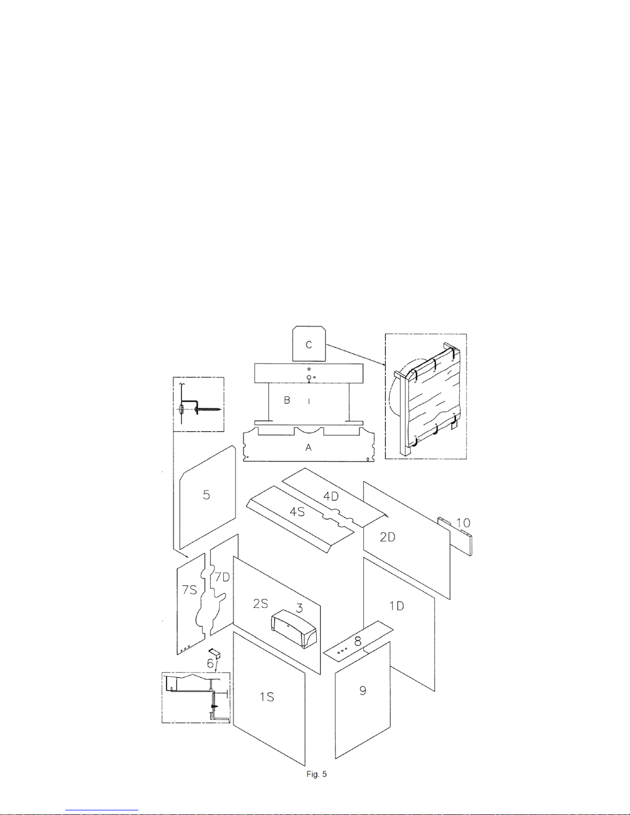
5.3 BOILER CASING mod. 160 GT/JB-270 GT/JB (Fig. 5)
• Fit the panel (1D) by hooking the upper profile to the square profile and the lower to the boiler fixing.
Repeat the same procedure for panel (1S).
• Fit the panel (2D) by hooking the upper profile to the square section and inserting it in the slots in the lower
panel. Repeat the procedure for panel (2S) with the burner-control panel connection cables passing through the aperture (for the wiring harness please refer to the control panel diagram and to the standard plug connection kit).
• Unwind the thermostat capillaries, fit the control panel to the side, fastening with the screw, then insert
the bulbs in the boiler pockets. Fit the upper panels (4S and 4D).
• Mount the panel (5); attach the support bracket (6) to the corner of the frame base, position the panel
(7D) and then the panel (7S) with plate attached to its side panels. Screw on tightly and plug the holes
with the appropriate caps. Attach the front/central panel with the plate (8) and the front/lower
panel (9). Finally, screw the document holder (10) on to the opposite side to the control panel.
Page 16
15
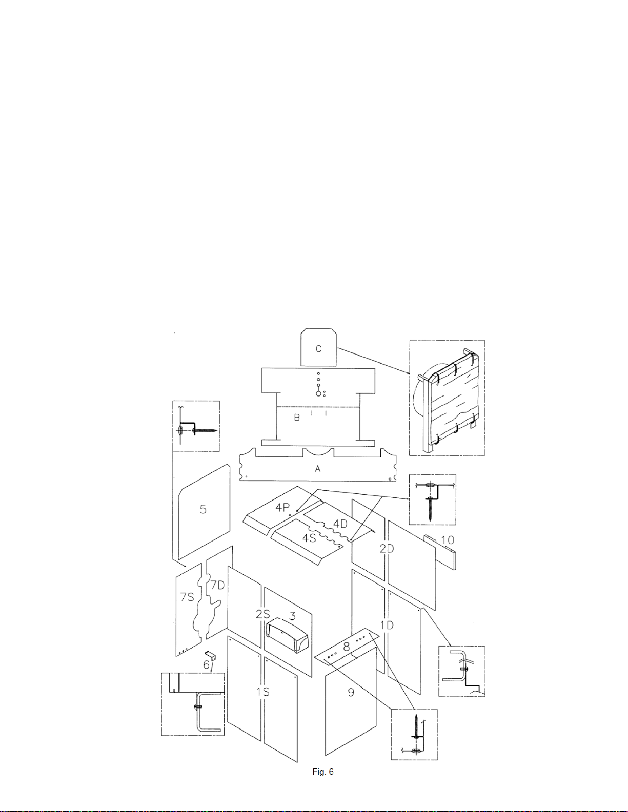
5.4 BOILER CASING mod. 350 GT/JB-670 JB (Fig. 6)
• Mount the panels (1D) fixing the lower folds on to the metal strut on the boiler and attaching the upper
ones to the centre with the appropriate screws. Repeat the same procedure for the panels (1S).
• Mount the panels (2D) fixing the upper folds to the rectangular section and inserting them into the appropriate
slits in the lower panels. Repeat the same procedure for the panels (2S) leaving the burner-control
panel connection cables sticking out from the existing opening (for the wiring harness please refer to the
control panel diagram and to the standard plugs connection kit).
• Unwind the thermostat capillaries, attach the control panel (3) to the side with a screw, then insert the
bulbs into the boiler pockets
• Mount the upper panels (4P), (4D) and (4S) with screws and plug the holes with the caps.
• Mount the panel (5); attach the support bracket (6) to the frame base, position the panel (7D) and then
the panel (7S) with plate attached to its side panels. Screw on tightly and plug the holes with the appropriate caps.
• Attach and screw on the front/central (8) and front/lower (9) panels.
• Finally, screw the document holder (10) on to the opposite side to the control panel.
Page 17

16
Calcium Carbonate Diagram
6.3 FILLING THE SYSTEM
The water must enter the system as slowly as possible, and in proportion to the rate of air purge from the
components involved. In the case of a system with a closed expansion tank, water is injected until the pressure
gauge reaches the static pressure for the tank. Then proceed to heat the water to the maximum allowed
plant temperature, but not higher than 90°C. During this operation, the air in the system purges from the
automatic or manual air separators fitted to the system. On completion of the air purge, bring the pressure to
the set value and close the manual and/or automatic water supply valve.
6 STARTING
IMPORTANT: before starng insert the ue gas baes completely in the ue-ways, pushing them in by at least 100 mm.
6.1 PRELIMINARY CHECKS
Before starting the boiler, make sure that:
- The plate data corresponds to the electrical, water and fueldata;
- The burner rating is compatible with that of the boiler;
- The burner and boiler instructions are in the boiler room;
- The chimney functions correctly;
- The ventilation openings are to current regulations
- The door, the combustion chamber and the burner plate are closed so that the boiler is air/gas tight at all positions;
- The system has been filled with water and that air locks have been eliminated;
- There is frost protection;
- The water circulation pumps operate correctly;
- The expansion tank/sealed system equipment and the safety valve(s) are correctly positioned and operate.
- Check the electrical system and that the thermostats are set and operate.
6.2 WATER TREATMENT
If the boiler is to be installed in an exisng system where there could be these should be reced or if the hardness of the
water is greater than 10 F, it will be necessary to use a strainer and a water soener for system water and control the pH if
above 8-9.
The most common problems in heating systems are Furring (calcareous deposits of Calcium Carbonate)
Furring impedes heat exchange between the hot flue gases and the water, thereby increasing the temperature of
parts exposed to the flame and reducing considerably the boiler life. Furring concentrates where the boiler wall temperature is high, and the best defence against this phenomenon is the ML boiler design that eliminates high temperature spots. Furring represents an insulation layer that decreases heat exchange, penalising boiler efficiency. This
means that a large part of the combustion heat is not transferred to the water, but leaves the boiler via the flue.
Water-side corrosion
Corrosion of metallic boiler surfaces, waterside ,
is due to Iron dissolving to form ions (Fe+).
In this process, the presence of any dissolved
gas plays a major role, in particular oxygen and carbon
dioxide. Often there are corrosion phenomena with
softened and demineralised water, which are by their
nature aggressive. In these cases though clearly
there will be no furring but corrosion remains a risk
and it will be required to condition the feed water with
corrosion inhibitors.
Page 18
17
7 OPERATION
7.1 OPERATION CHECKS
The heating system must be used suitably, ensuring on the one hand, optimum combustion with reduced
emission to the atmosphere of carbon monoxide, hydrocarbons and soot, and on the other avoiding all damage
to persons and property.
The pressurisation must remain within the limit values shown in the technical data table.
The burner switch should always remain on; this ensures that the boiler water temperature remains near the
value set by the thermostat.
In the case of ue gas leaks from the front of the boiler (door and burner plate), the closure e rods
of the single parts must be adjusted; if this is not sucient, replace the gaskets.
7.2 TEMPORARY BOILER STOP
To stop the boiler temporarily, set the main switch on the control panel to “OFF”.
7.3 PROLONGED BOILER STOP
Close the gas valve that is fitted upstream of the boiler.
WARNING: During long stoppages in winter and in order to avoid frost damage, drain both the sanitary water*
and the heating system water; drainage of the latter can be avoided by adding antifreeze.
• Boiler with hot water calorier.
7.4 PERIODICAL USER CHECKS
Check periodically that there is no air in the heating system check all AAV devises Periodically check the boiler
pressure.
7.5 MAINTENANCE AND CLEANING
maintenance and cleaning can be carried out after closing the fuel supply and switching off the electrical supply.
As economic operation depends on the cleanliness of the heat exchanger surfaces and on burner adjustment have
the burner settings checked by professionally qualified personnel.
Analyse the system water and allow for adequate water treatment to avoid the formaon of calcareous
incrustaons that inially reduce boiler eciency, and then lead to damage;
- Check that the Boiler and the flue gas sealing gaskets are in good order and if not replace;
- Periodically check the efficiency of the regulation and safety instruments on the system.
WARNING
Do not open the door and do not remove the fume chamber while the burner is in operaon. In all cases wait a few
minutes aer stopping the burner for the insulaon to cool.
WARNING: during long stoppages in winter and in order to avoid frost damage, drain both the sanitary water
and the heating system water; drainage of the latter can be avoided by adding antifreeze.
IMPORTANT
It is recommended to check periodically for possible scale deposits through the side inspecon plugs (see par. Technical
Data): if necessary, carry out chemical washing.
Page 19
18
 Loading...