

Strebel Mital, Montreux User Manual

0099
STREBEL MITAL
&
STREBEL MONTREUX
Fan Assisted Wall Mounted Gas
Combination
&
System Boilers
USER, INSTALLATION,
COMMISSIONING & MAINTENANCE
INSTRUCTIONS.
APR-01
- 1 -

Contents
1.0 Introduction ----------------------------------------------------------------------------------- 3
2.0 General Precautions ------------------------------------------------------------------------ 3
3.0 Installation ------------------------------------------------------------------------------------ 3
3.1 Reference Regulations ---------------------------------------------------------- 3
3.2 Packaging -------------------------------------------------------------------------- 3
3.3 Boiler Location -------------------------------------------------------------------- 3
4.0 Technical Data ------------------------------------------------------------------------------- 4
5.0 Ventilation ------------------------------------------------------------------------------------- 6
6.0 Flueing ----------------------------------------------------------------------------------------- 6
7.0 Boiler Siting ----------------------------------------------------------------------------------- 8
8.0 Flue Assembly ------------------------------------------------------------------------------- 8
9.0 Flue & Boiler Accessories------------------------------------------------------------------ 9
10.0 Gas Supply ----------------------------------------------------------------------------------- 10
10.1 L.P.G. Conversion ------------------------------------------------------------- 10
11.0 Cold Water Supply (Mital, Mital plus & Mital max only) --------------------------- 10
12.0 Sealed Primary System ------------------------------------------------------------------- 11
13.0 Electrical System ---------------------------------------------------------------------------- 12
13.1 Internal wiring ---------------------------------------------------------------------- 12
13.2 External Controls ----------------------------------------------------------------- 12
14.0 Commissioning ------------------------------------------------------------------------------ 17
14.1 Handing Over ---------------------------------------------------------------------- 18
15.0 Maintenance ---------------------------------------------------------------------------------- 19
15.1 Fault Finding ----------------------------------------------------------------------- 19
15.2 Fault Finding Guide -------------------------------------------------------------- 20
16.0 Users Instructions --------------------------------------------------------------------------- 21
Page No.
Illustrations:
Figure 1. Boiler Dimensions & Clearances Figure 14. Montreux Internal Wiring Diagram
Figure 2. Air Vent Positions Figure 15. Mital plus Internal Wiring Diagram
Figure 3. Flue Terminal Position Figure 16. Montreux plus & max Internal Wiring
Figure 4. Boiler & Manifold Fixing Points Diagrams
Figure 5. Manifold Assembly Figure 17. Mital max Internal Wiring Diagrams
Figure 6. Flue Adapters Figure 18. Honeywell V4600 Gas Valve
Figure 7. Coaxial Flue System Figure 19. SIT 826 Nova Gas Valve
Figure 8. Twin Pipe Flue System Figure 20. SIT 826 Nova Gas Valve, High and
Figure 9. Boiler Flue Gate Low Gas Pressure Adjustment.
Figure 10. CWS Flow Valve Figure 21. Burner Fixing Screws.
Figure 11. HWS Flow / Temp Graph Figure 22. Mital & Montreux Control Panel
Figure 12a - d. Resistance & Pump Diagram Figure 23. Mital plus, Mital max, Montreux plus &
Figure 13. Mital Internal Wiring Diagram Montreux max Control Panel
- 2 -

1.0 Introduction
Thank you for choosing our products. We
recommend that these instructions be used to ensure
the safe operation of the boiler and to maximise their
performance.
The data plate for the boilers is located behind the
control panel cover.
Boiler names:
Mital - wall hung gas-fired combination boiler with fan
assisted flue; output 23.2 kW.
Mital plus - room sealed wall hung gas-fired
combination boiler with fan assisted flue and
electronic ignition; output 23.2 kW.
Mital max - room sealed wall hung gas fired
combination boiler with fan assisted flue and
electronic ignition; output 31.3kW.
Montreux - wall hung gas-fired system boiler with fan
assisted flue; output 23.2 kW.
Montreux plus - room sealed wall hung gas-fired
system boiler with fan assisted flue and electronic
ignition; output 23.2 kW.
Montreux max - room sealed wall hung gas-fired
system boiler with fan assisted flue and electronic
ignition; output 31.3 kW.
2.0 General Precautions
• This instruction manual is an integral and
essential part of the appliance, and must be left
with the end user and stored near to the boiler for
further consultation during maintenance etc.
• These instructions must be read thoroughly before
proceeding, failure to follow the instructions may
affect the safety, performance and warranty of the
appliance.
• Installation must be carried out by professional,
qualified CORGI REGISTERED ENGINEERS in
compliance with all current regulations and
manufacturers instructions.
• The installation of the boiler must also be in
accordance with the current I.E.E. Regulations,
the By-laws of the Loc al Wat er Undert akin g, Loc al
Authority requirements and all relevant British
Standards.
• The appliance must be installed in a suitable
environment that is NOT explosive, flammable,
corrosive or damp.
• Neither the supplier or the manufacturer will be
responsible for any damage to property, persons,
animals or the boiler, as a result of tampering,
improper use, installation or maintena nce.
• Packaging parts (i.e. plastic bags, polystyrene,
wood, clips, nails, etc.) can be harmful to
children and must be disposed of immediately
and correctly.
• To avoid damage caused by low temperatures it is
recommended that the boiler should be drained
down if left u nused for a long period. Neit her the
supplier or manufacturer is responsible for faults,
break downs, water leakage or any c onsequential
damage caused b y low temperature.
• To comply with the Warranty these instructions
must be adhered t o and only original spare parts
and kits used.
• In the event of breakdown the appliance should be
isolated and a qualified CORGI REGISTERED
SERVICE ENGINEER contacted.
• This appliance MUST have an annual service and
inspection by a suitably qualified CORGI
REGISTERED ENGINEER.
3.0 Installation
3.1 Reference Regulations
Detailed recommendations are contained in the
following :
BS 5440 :1 & 2, BS 4543, BS 5540 :2, BS 6798, BS
5449, BS 5546, BS 6891, Gas Safety Regulations
1984. All other relevant regulations must be
adhered to whether they are listed above or not.
3.2 Packaging
The packing mat erial and the cardboard cover mu st
be removed without turning the boiler upside down.
The boiler should be kept in a vertical position
and on the polystyrene lower base. Never place
the boiler directly onto the floor.
To remove the cardboard cover open the base of the
box and lift the box off the boiler.
Each boiler is supplied in three separate containers:
1. boiler
2. connection manifold, valves and angled
connecting pipes.
3. flue kit
any extras or a dditions will be packed separately.
3.3 Boiler Location
Mital & Montreux - Both these appliances are NOT
ROOM SEALED and therefore must NOT
installed in a bedroom, bedsitting room or any room
containing a bath or a shower.
These boilers must be sited 0.5 metres from
combustible materials i.e. curtains etc.
Mital plus, Mital max, Montreux plus & Montreux
max are room sealed and can be installed in any
room, although particular attention is drawn to the
requirements of the IEE Regulations and, in
Scotland, the electrical provisions with respect to the
installation in a room containing a bath or shower.
If the boiler is to be installed in a room that
contains a bath or shower the boiler MUST be
be
- 3 -
situated so that it cannot be touched while the
person is using the bath or shower.
General
The wall must be flat and vertical, and of suitable
load bearing capacity.
Adequate space must be allowed around the boiler to
facilitate installation, servicing and maintenance, the
required clearances are shown in figure 1.
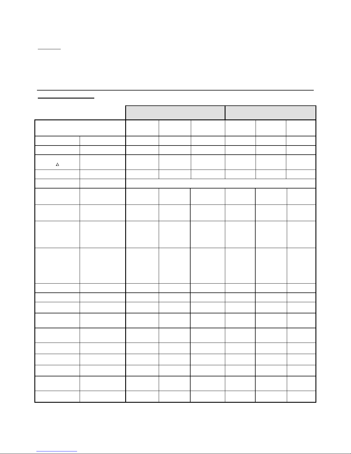
4.0 Technical Data
Combination Boilers System Boilers
The boiler MUST be positioned so the top of the
boiler is a minimum of 2.2 metres from floor level or
suitable provision made to restrict accidental access
to the top of the boiler.
The position must permit a satisfactory flue terminal
position.
Model
Input kW 13.2 - 26.4 13.2 - 26.4 17.4 - 34.8 13.2 - 26.4 13.2 - 26.4 17.4 - 34.8
Output kW 11.6 - 23.2 11.6 - 23.2 15.6 - 31.3 11.6 - 23.2 11.6 - 23.2 15.6 - 31.3
DHW Flow Rate
at 25°C
Flue Size mm 60 100 100 60 100 100
Electrical Supply
Heating Circuit
Pressure Bar
DHW Circuit
Pressure Bar
Dimensions (mm) Height
Clearances (mm) Top
Weight (empty) kg 43 49 69 39 45 55
Features: Fan Assisted
t
Electronic Ignition
Slow Start Burner
Safety Valve 3 Bar
Lt/min 13.3 13.3 17.9
max
min
max
min
Width
Depth
Bottom
Front
Sides
Room Sealed
Instantaneous
DHW capability
Built-in Pump
(Circulating)
Permanent Pilot
Overheat
Thermostat
Mital Mital
plus
3
0.5
6
0.4
850
450
350
400
400
350
25
3
0.5
6
0.4
850
450
350
400
400
350
25
X X X X X X
__
X X
X X X
X X X X X X
__
X
X X
__ __
X X X X X X
X X X X X X
X X X X X X
Mital
Montreux Montreux
max
-- -- --
230 volts - 50 Hz - Single Phase
3
0.5
6
0.4
850
600
350
400
400
350
25
3
0.5
-- -- --
850
450
350
400
400
350
25
__
__ __ __
__
X
Montreux
plus
3
0.5
850
450
350
400
400
350
25
max
3
0.5
850
600
350
400
400
350
25
X X
X X
__ __
- 4 -
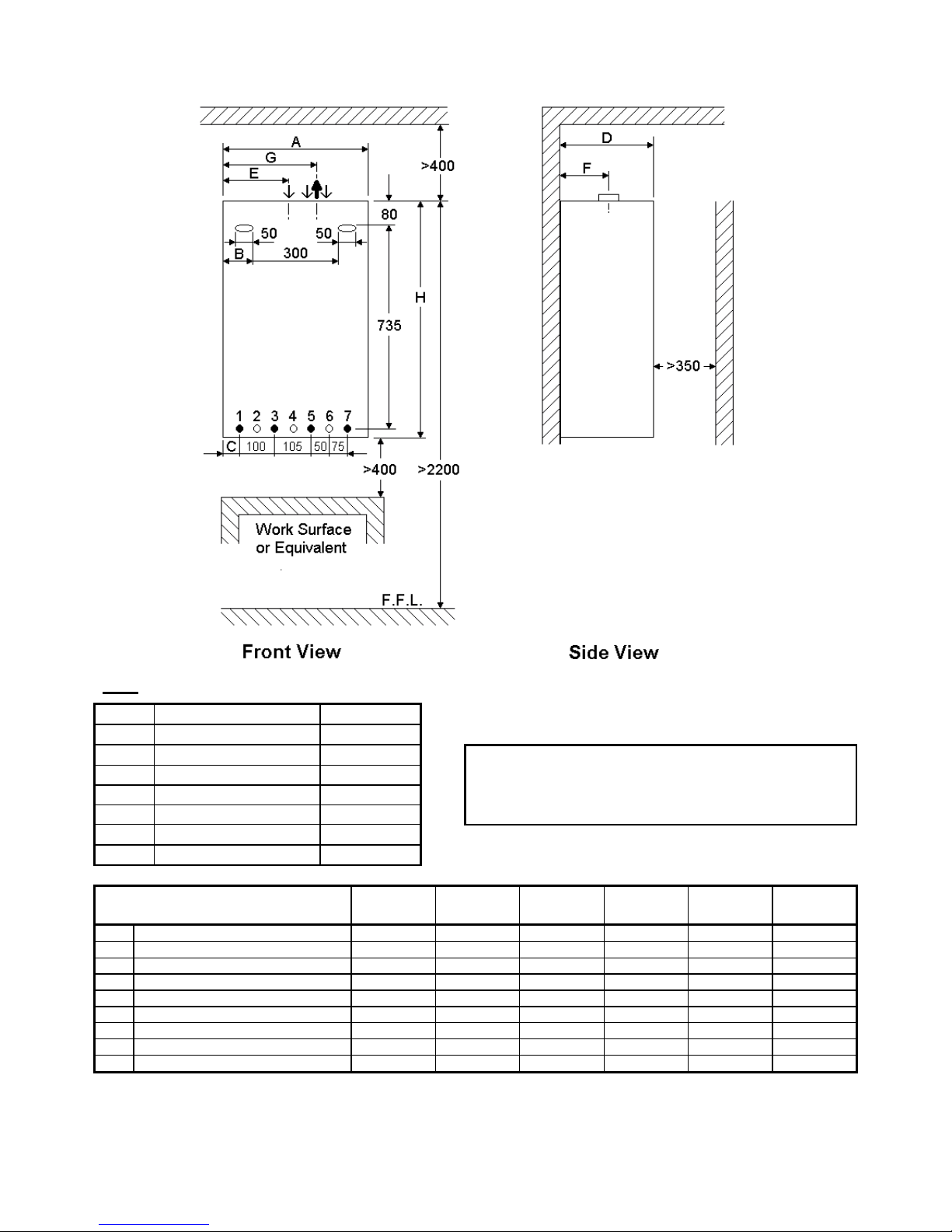
Figure.1 - Boiler Dimensions & Clearances.
KEY
Connections (mm)
1 DHW outlet 15
2 Safety valve discharge 15
3 Gas supply 15
4 Electrical cables -5 Mains water inlet 15
6 Heating flow 22
7 Heating return 22
Clearances (mm)
Top 400
Bottom 400
Front 350
Sides 25
MODEL Mital Mital Mital Montreux Montreux Montreux
DIMENSION plus max plus max
A Width of Unit 450 450 600 450 450 600
B Inside of fixing point 75 75 75 75 75 75
C Centre of DHW connection 55 55 55 55 55 55
D Depth of Unit 350 350 350 350 350 350
E Centre of combustion air inlet * -- 155 200 -- 155 200
F Centre Exhaust outlet 195 195 185 195 195 185
G Centre Exhaust outlet 265 265 310 265 265 310
H Height of Unit 850 850 850 850 850 850
Flue connection 60 100 60 100 100 100
* Connection for Mital plus, Mital max, Montreux plus & Montreux max when used with a twin flue system.
- 5 -
5.0 Ventilation
Mital & Montreux
Combustion ventilation - a permanent air vent is required directly to outside, or to an adjacent room ventilat ed to
outside, wit h a m i ni m um o f 1 00 c m ² of free air space. If air ventilation i s to be via anot her r oo m, the room cann ot be
a bathroom, bedroom, garage or a room that contains either a shower or a bath.
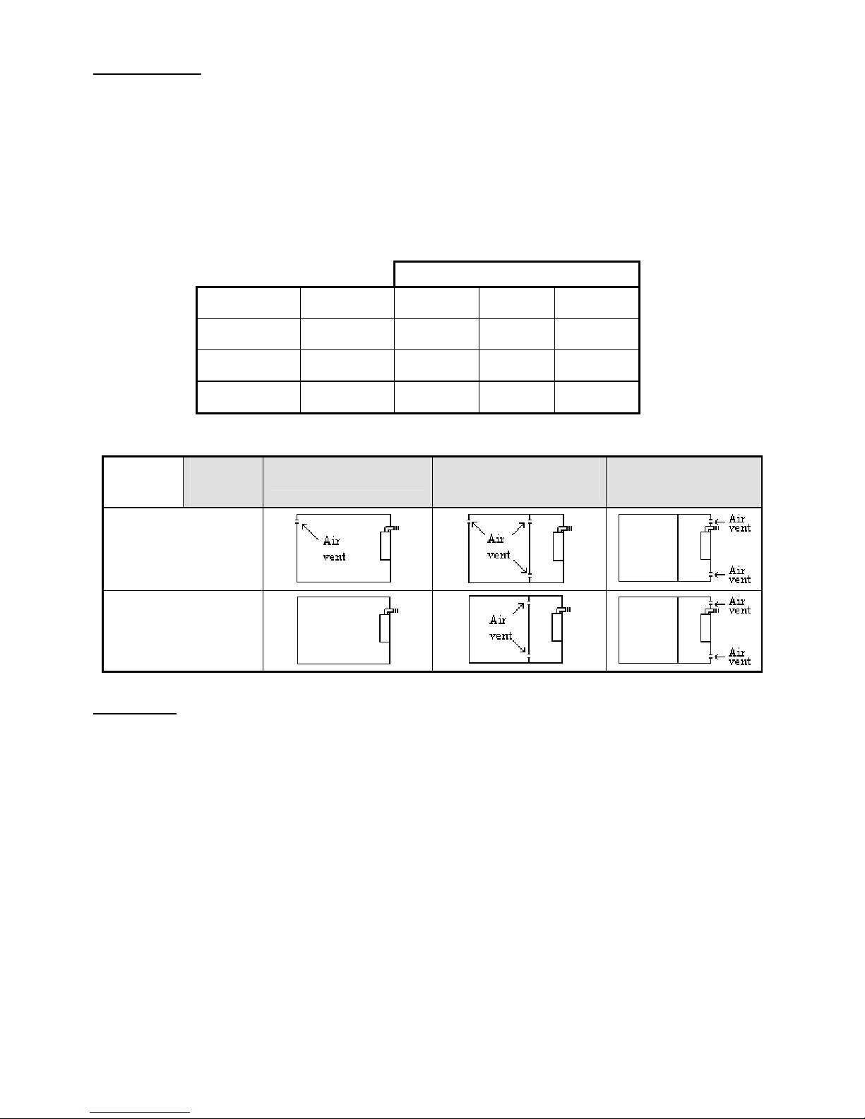
Compartment V entilation - if the boiler i s to be instal led in either a c upboard or compar tment, perman ent air vents
are required at high and low levels see table below for sizes. Where the compartment air vents communicate with a
room, the room must itself be vent i l at e d wit h a mi ni m u m of 10 0 cm ² .
The air vents must both communicate with the same wall/room, and if communicated into a room, the room must
not be a bathroom, bedroom, garage or a room that contains either a shower or a bath.
Compartment Ventilation
Boiler Type
Mital &
Montreux
Mital plus &
Montreux plus
Mital max &
Montreux max
Combustion
Ventilation
100 cm²
None
Required
None
Required
Position of
vents
High
Low
High
Low
High
Low
Air from
Room
201 cm²
402 cm²
201 cm²
201 cm²
285 cm²
285 cm²
Air from
Outside
100 cm²
201 cm²
100 cm²
100 cm²
142 cm²
142 cm²
Figure. 2 - Air Vent Positions.
Boiler
type
Boiler
location
In a Room
In a compartment
Vented to a Room
In a compartment
Vented to Outside
Mital
Montreux
Mital plus
Mital max
Montreux plus
Montreux max
6.0 Flueing
General Position
• Siting should not cause an obstruction or the discharge a nuisance. It should be remembered that in certain
weather conditions a terminal may steam.
• If the terminal i s below 2 metre s from floor lev el or where people have ac cess a termi nal guard must be fitted.
The guard must be symmetrically positioned ensuring a minimum of 50mm gap between the end of the terminal
and the guard.
• If the terminal is within 600mm below plastic guttering, then an aluminium shield of 1.25 metres long should be
fitted to the under side of the guttering.
• The terminal or flue must not be closer than 25mm to any combustible material.
- 6 -
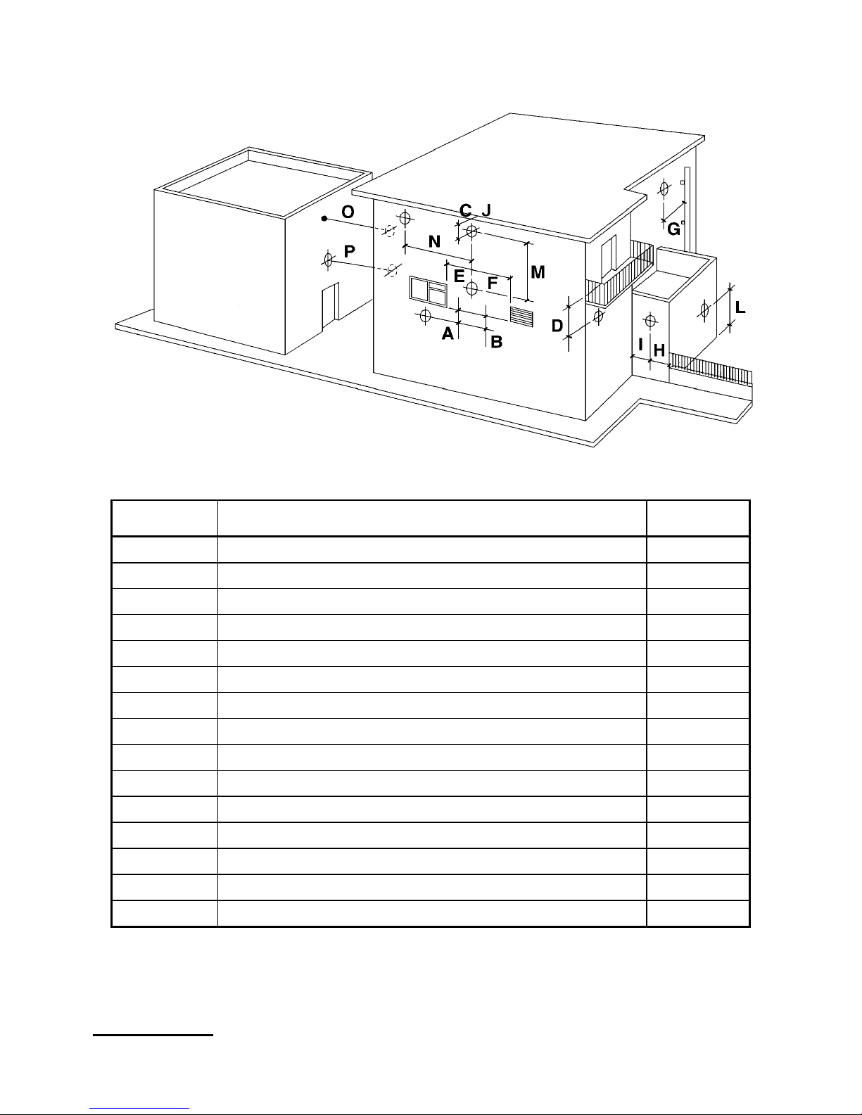
Figure. 3 - Flue Terminal Position
Dimension Minimum Distances from the Flue Terminal (mm)
A
B
C
D
E
F
G
H
I
J
L
M
N
O
Directly below an opening window 300
Directly below an air vent 300
Below gutters, soil pipes or drain pipes 75
Below a Balcony 200
Horizontal from a window or door on the same wall 300
Horizontal from an air vent on the same wall 300
From vertical drain pipes and soil pipes 75
From external corners 300
From internal corners 300
Below eaves 200
Above ground, roof or balcony level 300
Vertical from a terminal on the same wall 1500
Horizontal from a terminal on the same wall 300
From a surface facing a terminal 600
P
From a terminal facing a terminal 1200
7.0 Boiler Siting
- 7 -
 Loading...