

Strebel K4G1H24PX, K4G1H24ZX, K4G2H24ZX, K4G3H24ZX, K4G3H24PX Product Manual
...
Product Manual
Gas Condensing Boiler K4


K4
Changes in models reserved.
Dimensions not binding!
Safety Information
Safety Information
- Every person who is intending to operate this boiler is obligated to
read this manual carefully, especially the safety instructions. This includes indivi-
duals which are cleaning or maintaining the boiler.
Otherwise, the legal warranty expires.
- Please keep and preserve this manual.
Warranty and Liability for Defects
STREBEL provides a warranty on the boiler K4 for the period of 24 months from the product commissioning date. Within this warranty the manufacturer agrees to remove the defects of the product in
the form of a repair free of charge.
In order to recognize the warranty the manufacturer requires:
- commissioning of the K4 condensing gas boiler by an authorized servicing organisation
contracted by the manufacturer. This firm is obliged to send a notification on commissioning
of said boiler in writing to the manufacturer not later than 20 days upon commissioning to
the following address:
Strebel Ltd. Unit 10, Invincible Road,
Farnborough, Hampshire, GU14 7QU UNITED KINGDOM
Fax: +44 (0) 1276 685 405, Mail: info@strebel.co.uk
- in accordance with act no. 458/2000 Coll. “on the Conditions for Doing Business and
Exercising State Administration in the Energy Sectors and amending certain acts
(the Energy Act) and ČSN 38 6405 change 1 5/99, EN 1775 to inspect the gas boiler on
a regular basis once a year. The inspections can be performed only by a contacted servicing
organisation authorized by the manufacturer, i.e., by STREBEL Ltd. This firm is obliged to
record and document on the implemented warranty and after-warranty repairs and on the
execution of the regular annual inspections of the boiler in the annexure to the warranty
sheet in this manual.
Each defect must be reported immediately after its detection, always by phone as well as in a
written form. A failure to meet the specified instructions must result in cancellation of the warranty
by the manufacturer.
The warranty does not apply to:
- defects caused by improper assembly and improper attendance of the product and defects
caused by improper maintenance, see chap. 7;
- defects caused by failure to observe the instructions specified in this manual including by
failure to observe water quality in the heating system;
- product damage in the course of transport or another mechanical damage or unsuitable
storage (for example water);
- consumables, i.e. electrodes, water/gas seal and fuses.
- defects caused by natural disasters or force majeure.
The manufacturer reserves the right for changes performed within the product innovation process
which are not necessarily contained in this manual.
3

K4
Changes in models reserved.
Dimensions not binding!
Safety Information
Usage Of This Boiler
- It is forbidden to intervene with any secured parts.
- In case water is leaking from the boiler, stop its operation immediately and have competent
service personnel at the damage.
- The boiler is fully automatic therefore we do not recommend disconnecting it from power
supply (230 V/50 Hz) unless necessary.
- If any building reconstructions are performed in the close vicinity of the boiler, turn off the
boiler with a sufficient lead time and protect it from polluting.
- The user may only modify the operation parameters in the range that is prescribed by this
manual. The use of other settings than those listed in this manual can cause malfunctions in
the system.
- To replace defective parts of the boiler, only use original STREBEL spare parts.
Possible Risks
- No flammable objects must be placed, built or suspended near the boiler and flue gas
ducting (a safe distance of the appliance from flammable materials is 50 mm from
the boiler front and 10 mm in other directions).
- Avoid cleaning of the boiler by flammable or explosive agents.
- Children and people with physical or mental impairments who are not able to safely operate
the boiler should be supervised in order to ensure that they do not interact with the
appliance.
- In winter (if leaving for a holiday, for instance) it is necessary to ensure the inspection of
functionality of the boiler and the entire heating system in order to avoid possible water
freezing, as this may result in equipment damage due to some external reasons (such as
electricity or heating gas supply outage, and so on).
- The manufacturer recommends the use of antifreeze Alphi 11 manufactured by Fernox or
X500 manufactured by Sentinel approved for the Sermeta heat exchangers.
- In case of boilers with flue gas connection into the surrounding environment through the
peripheral external wall of the building, it is necessary to check whether the condensed
water from the flue gas in the flue basket does not freeze in a frosty weather.
- While checking the tightness of the gas distribution and the valve connection, it is
necessary to be careful not to wet the coil of the gas valve!
- In case of fire on any of the boiler parts, extinguish them like you would so with electric
equipment.
- It is necessary to avoid air pollution with halogen hydrocarbons (contained, for example, in
sprays, solvents, paints, glues) and dust coming into the boiler from the fresh air intake.
4

K4
Changes in models reserved.
Dimensions not binding!
Contents
5
1 Boiler Application and Benefits ...........................................................................................................................................6
1.1 Boiler Benefits: .................................................................................................................................................................6
2 Boiler Versions ....................................................................................................................................................................... 6
3 Technical Data .........................................................................................................................................................................7
3.1 Boiler Connection K4, 24 kW, 3.2 Boiler connection K4, 24 kW ......................................................................................7
3.3 Thermal Parameters K4, 24 kW ....................................................................................................................................... 8
3.4 Boiler connection K4, 33 kW, 3.5 Boiler connection K4, 33 kW ..................................................................................... 9
3.6 Thermal Parameters K4, 33 kW ..................................................................................................................................... 10
4 Boiler Design......................................................................................................................................................................... 19
4.1 Flue Options, 4.2 Dimensions, 4.3 Control Feature ....................................................................................................... 19
4.4 Removing The Front Cover, 4.5 Main Boiler Parts ......................................................................................................... 20
4.6 Heat Exchanger Scheme ................................................................................................................................................ 22
5 Installation ............................................................................................................................................................................. 23
5.1 Delivery an Accessory, 5.2 Instructions Before Putting Into Operation ........................................................................ 23
6 Operation................................................................................................................................................................................ 24
6.1 Control Panel ................................................................................................................................................................. 24
6.2 Modes Of Operation ...................................................................................................................................................... 25
6.3 Lockout Condition Codes ............................................................................................................................................... 27
6.4 Blocking Codes .............................................................................................................................................................. 29
6.5 Additional Functions, 6.6 Open Therm Communication ................................................................................................ 31
6.7 Installer Mode ............................................................................................................................................................... 32
7 Maintenance ......................................................................................................................................................................... 34
8 Installation ............................................................................................................................................................................. 35
8.1 Possible Placement, 8.2 Boiler Installation ................................................................................................................... 36
8.3 Connection To The Heating System And Water Filling, 8.4 Gas Connection................................................................ 38
8.5 Electric Power Supply Connection, 8.6 Condensate Discharge .................................................................................... 38
8.7 Flue Gas Ducting, 8.8 Boiler Electrical Wiring .............................................................................................................. 39
9 Flue Gas Ducting................................................................................................................................................................... 45
9.1 Flue Gas Ducting Examples, 9.2 STARR D80 And FLEX 80 System Connection ........................................................... 47
9.4 IK 60/100, 80/125 System Connection .......................................................................................................................... 50
9.5 Pressure Losses Of Chimney Flue Elements .................................................................................................................. 52
10 Commissioning.................................................................................................................................................................... 53
10.1 Instructions Before Putting Into Operation .................................................................................................................. 54
10.2 Boiler Setting ............................................................................................................................................................... 55
10.3 Fuel Conversion, 10.4 Electronics Setting ................................................................................................................... 56
11 Servicing .............................................................................................................................................................................. 59
12 Instructions For Disposal After Service Life ................................................................................................................. 61
Annex ......................................................................................................................................................................................... 62

K4
Changes in models reserved.
Dimensions not binding!
General Information
Boiler Versions
1 Boiler Application and Benets
The K4 condensing boiler has been designed for combustion of low pressure natural gas.
The boiler size is suitable for heating of family homes and apartments as well as recreational facilities
as. The condensation heat output is 5 – 24 kW, 10 – 33 kW depending on model.
The boiler body efficiency at the 50/30 °C temperature gradient varies in a range of 101 – 105 % depending on the required output.
1.1 Boiler Benets:
- High combustion efficiency
- Low gas consumption
- Smooth output modulation
- Easy attendance and maintenance
- Select from combination or heating only boilers
- Reliability of the regulation and safety components
- Low weight
- Equithermal boiler regulation
- Automatic anti-freezing protection (when connected to power supply).
2 Boiler Versions
In your order specify the order specification code:
K4 ... Name of boiler series
Added specifics:
X
1
... Heat exchanger: G: stainless Steel
X
2
... Water heating: 1: without installed three-way valve with a pump
2: three-way valve, pump, HSW exchanger
3: with a three-way valve with a pump
X
3
... Electrical equipment: H: Honeywell
X
4
... Output: 24: 24 kW, 33: 33 kW
X
5
... Fuel: Z: natural gas, P: propane
X
6
... Cover color: W: white, R: red, B: black
Conversion of the K4 boiler from natural gas to propane and vice-versa can be performed by a contracted service provider only.
Chimney flue made by ALMEVA has been certified for this boiler. If you use chimney flue made by a
different producer, it is necessary to use a system with identical parameters as for the certified type
of the chimney flue.
6
K4
Changes in models reserved.
Dimensions not binding!
Technical Data
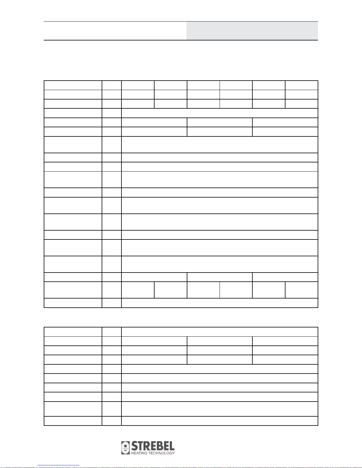
K4G1H24ZX K4G1H24PX K4G2H24ZX K4G2H24PX K4G3H24ZX K4G3H24PX
Fuel type [-] Natural gas Propane Natural gas Propane Natural gas Propane
Category of appliance [-] I
2H
I
2E
I
3P
I2H I
2E
I
3P
I2H I
2E
I
3P
Version C13,C33, C43, C53, C
83
Weight [kg] 26 27.5 26.5
Water volume [l] 2 3 2
Boiler dimensions
– width
[mm]
460
– depth [mm] 350
– height [mm] 720
Ø of combustion air
connection
[mm] 80/100 (see fig. no 10)
Ø flue gas socket [mm] 80, 60
Working water overpressure
[bar] 3
Testing water overpressure
[bar] 5
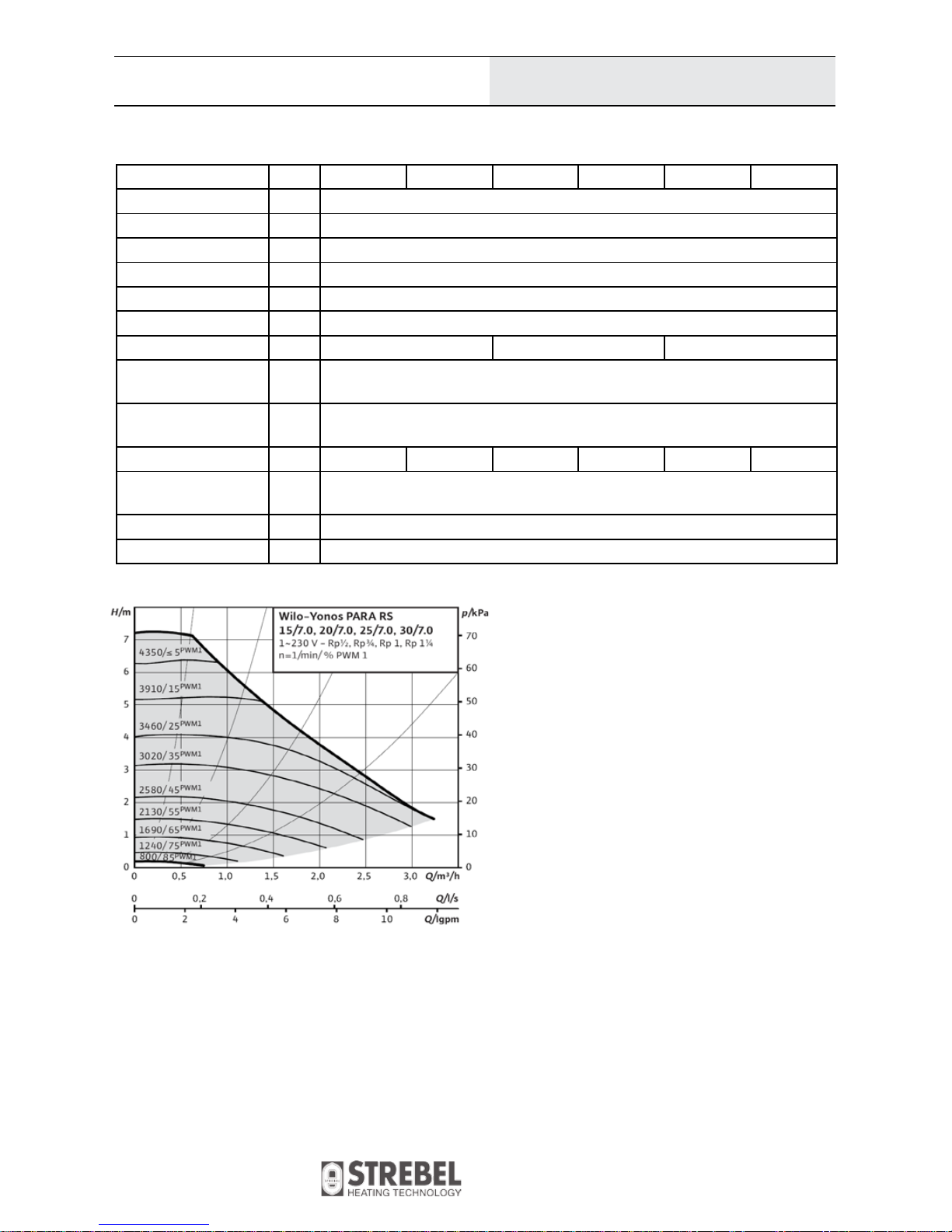
Pressure loss [-] See diagram 1
Maximum permitted
working temperature
[°C] 85
Heating water setting
range
[°C] 25–85
Hot water setting range [°C] - 35–60 35–60
Fuel connection pressure
[mbar] 20 37 20 37 20 37
Noise level [dB] < 50
3.2 Boiler connection K4, 24 kW
- Heating flow/return Inch 3/4“
- Hot water flow Inch - 1/2“ 1/2“
- Hot water return Inch - 1/2“ 3/4“
- Filling valve Inch 1/2“ - -
- condensate outlet [mm] Ø 25
- safety valve output [mm] Ø 21.2
- gas inlet Inch 3/4“
Connecting voltage 1/N/PE 230VAC 50 Hz, TN-S
El. power consumption
including pump
[W] 110
El. covering IP 40
3 Technical Data
3.1 Boiler Connection K4, 24 kW
7
K4
Changes in models reserved.
Dimensions not binding!
Technical Data
K4G1H24ZX K4G1H24PX K4G2H24ZX K4G2H24PX K4G3H24ZX K4G3H24PX
Boiler output range [kW] 5–24
Nom. output 80/60°C [kW] P=22.2
Nom. output 50/30°C [kW] P=24
Min. output 50/30°C [kW] P=5
Max. nom. heat input [kW] Q=22.8
Min. nom. heat input [kW] Q=4.6
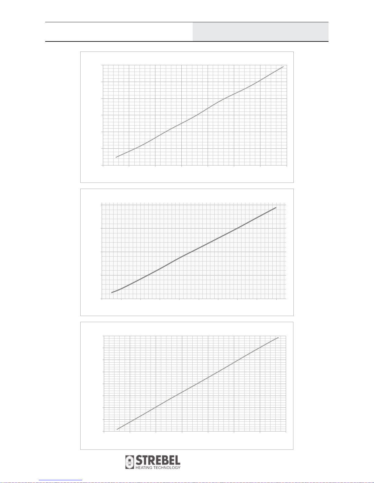
DHW flow with ΔT [l/min] - See diagram 2 -
Boiler efficiency at
nominal output 80/60°C
[%] Up to 98
Boiler efficiency at
nominal output 50/30°C
[%] Up to 105
Volume flow rate of fuel [m
3
/h] 0.5 – 2.4 0.2–0.9 0.5–2.4 0.2 – 0.9 0.5–2.4 0.2 –0.9
Mass flow rate of flue
gas
[kg/h] 8–45
NO
x
class [-] 5
Flue gas temp. (max.) [°C] 85
3.3 Thermal Parameters K4, 24 kW (comparison conditions 15 °C and 101.325 kPa, dry gas)
Diagram 1
8
K4
Changes in models reserved.
Dimensions not binding!
Technische Daten
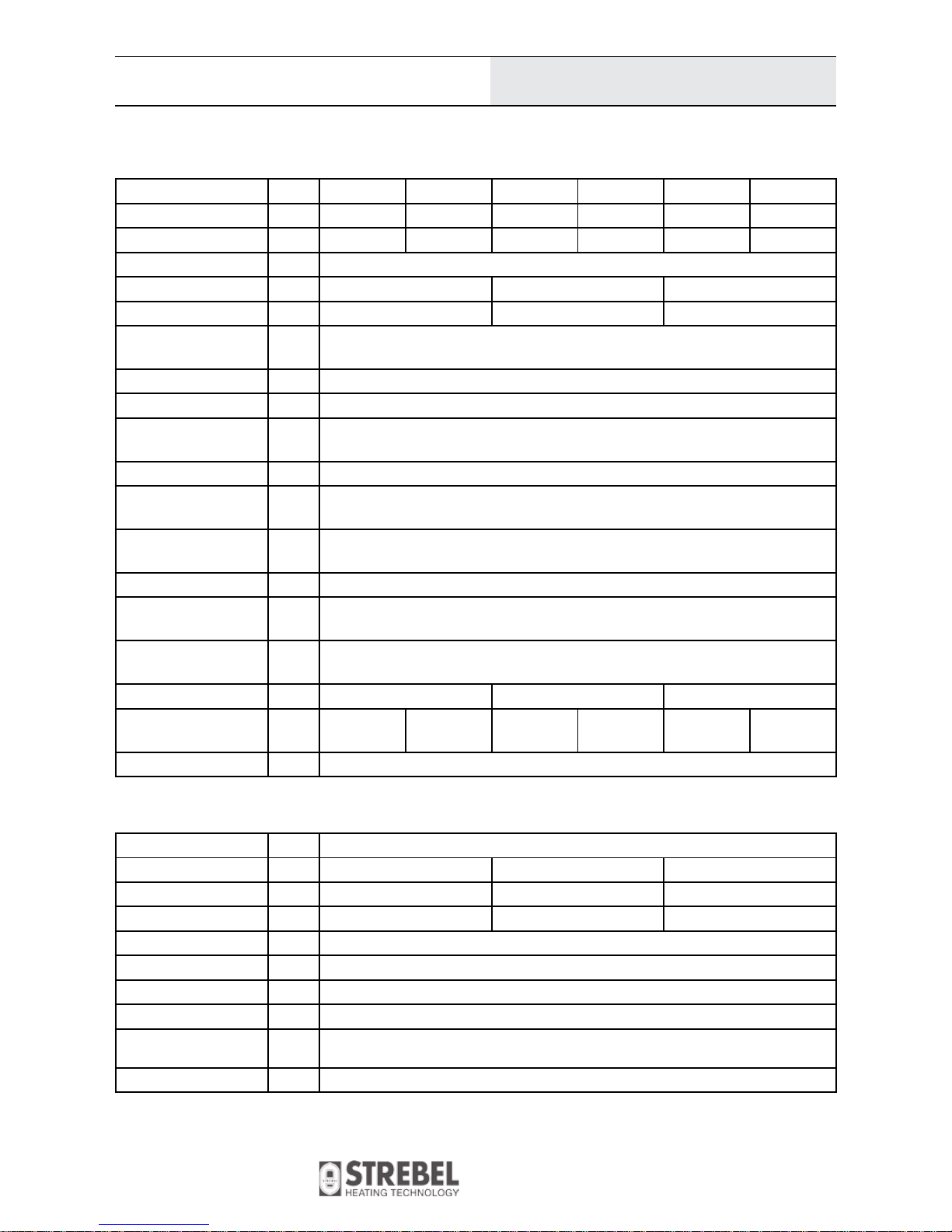
K4G1H24ZX K4G1H24PX K4G2H24ZX K4G2H24PX K4G3H24ZX K4G3H24PX
Fuel type [-] Natural gas Propane Natural gas Propane Natural gas Propane
Category of appliance [-] I
2H
I
2E
I
3P
I2H I
2E
I
3P
I2H I
2E
I
3P
Version C13,C33, C43, C53, C
83
Weight [kg] 28 29.5 28.5
Water volume [l] 3 4 3
Boiler dimensions
– width
[mm]
460
– depth [mm] 350
– height [mm] 720
Ø of combustion air
connection
[mm] 80/100 (see fig. no 10)
Ø flue gas socket [mm] 80, 60
Working water overpressure
[bar] 3
Testing water overpressure
[bar] 5
Pressure loss [-] See diagram 1
Maximum permitted
working temperature
[°C] 85
Heating water setting
range
[°C] 25–85
Hot water setting range [°C] - 35–60 35–60
Fuel connection pressure
[mbar] 20 37 20 37 20 37
Noise level [dB] < 50
3.5 Boiler connection K4, 33 kW
- Heating flow/return Inch 3/4“
- Hot water flow Inch - 1/2“ 1/2“
- Hot water return Inch - 1/2“ 3/4“
- Filling valve Inch 1/2“ - -
- condensate outlet [mm] Ø 25
- safety valve output [mm] Ø 21.2
- gas inlet Inch 3/4“
Connecting voltage 1/N/PE 230VAC 50 Hz, TN-S
El. power consumption
including pump
[W] 110
El. covering IP 40
3.4 Boiler connection K4, 33 kW
9

K4
Changes in models reserved.
Dimensions not binding!
Technische Daten
K4G1H24ZX K4G1H24PX K4G2H24ZX K4G2H24PX K4G3H24ZX K4G3H24PX
Boiler output range [kW] 6.5–33
Nom. output 80/60°C [kW] P=30.5
Nom. output 50/30°C [kW] P=33
Min. output 50/30°C [kW] P= 6.5
Max. nom. heat input [kW] Q=31.4
Min. nom. heat input [kW] Q=46.3
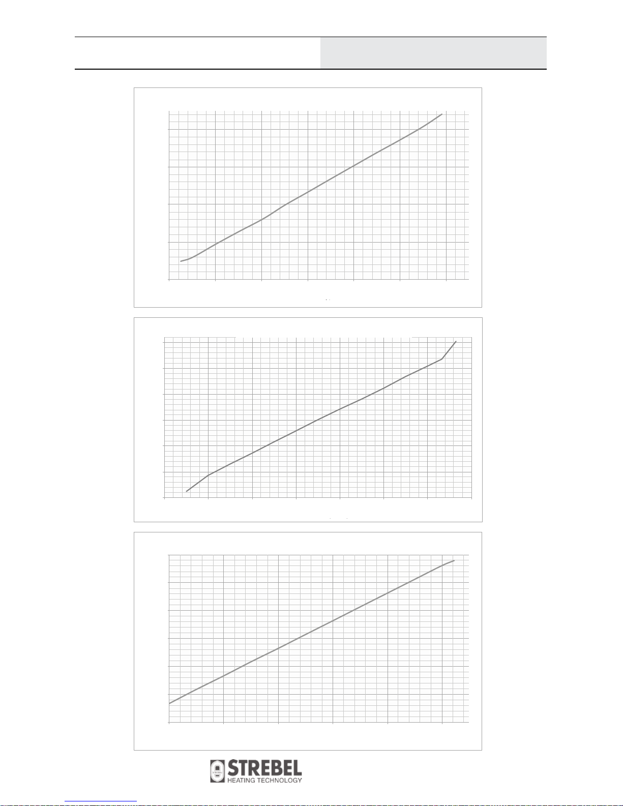
DHW flow with ΔT [l/min] - See diagram 3 -
Boiler efficiency at
nominal output 80/60°C
[%] Up to 98
Boiler efficiency at
nominal output 50/30°C
[%] Up to 105
Volume flow rate of fuel [m
3
/h] 0.68–3.3 0.28–1.28 0.68–3.3 0.28–1.28 0.68–3.3 0.28–1.28
Mass flow rate of flue
gas
[kg/h] 11–62
NO
x
class [-] 5
Flue gas temp. (max.) [°C] 85
3.6 Thermal Parameters K4, 33 kW (comparison conditions 15 °C and 101.325 kPa, dry gas)
Diagram 1
10
K4
Changes in models reserved.
Dimensions not binding!
Technical Data
General Information
4,50
6,50
8,50
10,50
12,50
14,50
16,50
2,50 3,50 4,50 5,50 6,50 7,50 8,50 9,50
Výkon kotle (kW)
Průtok TV (l/min)
K4G2H24.. Ohřev TV -∆T 25°C
4,00
9,00
14,00
19,00
24,00
2,00 3,00 4,00 5,00 6,00 7,00 8,00 9,00 10,00 11,00
Výkon kotle (kW)
Průtok TV (l/min)
K4G2H24.. Ohřev TV -∆T=30°C
7,00
9,00
11,00
13,00
15,00
17,00
19,00
21,00
23,00
2,50 3,50 4,50 5,50 6,50 7,50 8, 50 9,50
Výkon kotle (kW)
Průtok TV (l/min)
K4G2H24.. Ohřev TV -∆T 35°C
K4G2H24.. Hot water heating - ΔT 25 °C
K4G2H24.. Hot water heating - ΔT 30 °C
K4G2H24.. Hot water heating - ΔT 35 °C
Boiler power (kW)
Boiler power (kW)
Hot water flow rate (l/min)
Hot water flow rate (l/min)
Hot water flow rate (l/min)
11
K4
Changes in models reserved.
Dimensions not binding!
Technical Data
General Information
4,00
9,00
14,00
19,00
24,00
3,00 5,00 7,00 9,00 11,00 13,00 15,00
Výkon kotle (kW)
Průtok TV (l/min
)
K4G2H33.. Ohřev TV -∆T 35°C
4,00
9,00
14,00
19,00
24,00
29,00
34,00
2,00 4,00 6,00 8,00 10,00 12,00 14,00 16,00
Výkon kotle (kW)
Průtok TV (l/min)
K4G2H33.. Ohřev TV - ∆T 30°C
4,00
9,00
14,00
19,00
24,00
29,00
34,00
3,00 5,00 7,00 9,00 11,00 13,00
Výkon kotle (kW)
Průtok TV (l/min
)
K4G2H33.. Ohřev TV -∆T 35°C
K4G2H33.. Hot water heating - ΔT 25 °C
K4G2H33.. Hot water heating - ΔT 30 °C
K4G2H33.. Hot water heating - ΔT 35 °C
Boiler power (kW)
Boiler power (kW)
Boiler power (kW)
Hot water flow rate (l/min)
Hot water flow rate (l/min)
Hot water flow rate (l/min)
12
K4
Changes in models reserved.
Dimensions not binding!
Technical Data
General Information
Information requirements for boiler space heaters, boiler combination heaters
and cogeneration space heaters
Model(s): VIADRUS K4G1H24XX
Condensing boiler: yes
Low-temperature (**) boiler: no
B1 boiler: no
Cogeneration space heater: no If yes, equipped with a supplementary heater:
Combination heater: no
Item
Symbol
Value
Unit
Item
Symbol
Value
Unit
Rated heat output
Prated 24 kW
Seasonal space heating energy
efficiency
ƞ
s
90 %
For boiler space heaters and boiler combination heaters: Useful
heat output
For boiler space heaters and boiler combination heaters: Useful
efficiency
At rated heat output and hightemperature regime (*)
P
4
24 kW
At rated heat output and hightemperature regime (*)
ƞ
4
97,53 %
At 30 % of rated heat output and
low-temperature regime (**)
P
1
4 kW
At 30 % of rated heat output and lowtemperature regime (**)
ƞ1105,72 %
Auxiliary electricity consumption Other items
At full load el
max
0,02 kW Standby heat loss P
stby
0,045 kW
At part load el
min
0,011 kW Ignition burner power consumption P
ign
- kW
In standby mode P
SB
0,003 kW Emissions of nitrogen oxides NO
x
25
mg/
kWh
Contact details
VIADRUS a.s.
Bezručova 300
Bohumín
735 81
Czech Republic
(*) High-temperature regime means 60 °C return temperature at heater inlet and 80 °C feed temperature at heater outlet.
(**) Low temperature means for condensing boilers 30 °C, for low-temperature boilers 37 °C and for other heaters 50 °C return
temperature (at heater inlet).
K4G1H24XX
Strebel Ltd.
Unit 10, Invincible Road,
Farnborough, Hampshire, GU14 7QU
UNITED KINGDOM
13
K4
Changes in models reserved.
Dimensions not binding!
Technical Data
General Information
Information requirements for boiler space heaters, boiler combination heaters
and cogeneration space heaters
Model(s): VIADRUS K4G2H24XX
Condensing boiler: yes
Low-temperature (**) boiler: no
B1 boiler: no
Cogeneration space heater: no If yes, equipped with a supplementary heater:
Combination heater: yes
Item
Symbol
Value
Unit
Item
Symbol
Value
Unit
Rated heat output
Prated 24 kW
Seasonal space heating energy
efficiency
ƞ
s
90 %
For boiler space heaters and boiler combination heaters: Useful
heat output
For boiler space heaters and boiler combination heaters: Useful
efficiency
At rated heat output and hightemperature regime (*)
P
4
24 kW
At rated heat output and hightemperature regime (*)
ƞ
4
97,53 %
At 30 % of rated heat output and
low-temperature regime (**)
P
1
4 kW
At 30 % of rated heat output and lowtemperature regime (**)
ƞ1105,72 %
Auxiliary electricity consumption Other items
At full load el
max
0,02 kW Standby heat loss P
stby
0,045 kW
At part load el
min
0,011 kW Ignition burner power consumption P
ign
- kW
In standby mode P
SB
0,003 kW Emissions of nitrogen oxides NO
x
25
mg/
kWh
For combination heaters:
Declared load profile
XL Water heating energy efficiency ƞ
wh
84 %
Daily electricity consumption Q
elec
0,204 kWh Daily fuel consumption Q
fuel
23,215 kWh
Contact details
VIADRUS a.s.
Bezručova 300
Bohumín
735 81
Czech Republic
(*) High-temperature regime means 60 °C return temperature at heater inlet and 80 °C feed temperature at heater outlet.
(**) Low temperature means for condensing boilers 30 °C, for low-temperature boilers 37 °C and for other heaters 50 °C return
temperature (at heater inlet).
K4G2H24XX
Strebel Ltd.
Unit 10, Invincible Road,
Farnborough, Hampshire, GU14 7QU
UNITED KINGDOM
14

K4
Changes in models reserved.
Dimensions not binding!
Technical Data
General Information
Information requirements for boiler space heaters, boiler combination heaters
and cogeneration space heaters
Model(s): VIADRUS K4G3H24XX
Condensing boiler: yes
Low-temperature (**) boiler: no
B1 boiler: no
Cogeneration space heater: no If yes, equipped with a supplementary heater:
Combination heater: yes
Item
Symbol
Value
Unit
Item
Symbol
Value
Unit
Rated heat output
Prated 24 kW
Seasonal space heating energy
efficiency
ƞ
s
90 %
For boiler space heaters and boiler combination heaters: Useful
heat output
For boiler space heaters and boiler combination heaters: Useful
efficiency
At rated heat output and hightemperature regime (*)
P
4
24 kW
At rated heat output and hightemperature regime (*)
ƞ
4
97,53 %
At 30 % of rated heat output and
low-temperature regime (**)
P
1
4 kW
At 30 % of rated heat output and lowtemperature regime (**)
ƞ1105,72 %
Auxiliary electricity consumption Other items
At full load el
max
0,02 kW Standby heat loss P
stby
0,045 kW
At part load el
min
0,011 kW Ignition burner power consumption P
ign
- kW
In standby mode P
SB
0,003 kW Emissions of nitrogen oxides NO
x
25
mg/
kWh
For combination heaters:
Declared load profile
XL Water heating energy efficiency ƞ
wh
81 %
Daily electricity consumption Q
elec
0,222 kWh Daily fuel consumption Q
fuel
24,301 kWh
Contact details
VIADRUS a.s.
Bezručova 300
Bohumín
735 81
Czech Republic
(*) High-temperature regime means 60 °C return temperature at heater inlet and 80 °C feed temperature at heater outlet.
(**) Low temperature means for condensing boilers 30 °C, for low-temperature boilers 37 °C and for other heaters 50 °C return
temperature (at heater inlet).
K4G3H24XX
Strebel Ltd.
Unit 10, Invincible Road,
Farnborough, Hampshire, GU14 7QU
UNITED KINGDOM
15

K4
Changes in models reserved.
Dimensions not binding!
Technical Data
General Information
Information requirements for boiler space heaters, boiler combination heaters
and cogeneration space heaters
Model(s): VIADRUS K4G1H33XX
Condensing boiler: yes
Low-temperature (**) boiler: no
B1 boiler: no
Cogeneration space heater: no If yes, equipped with a supplementary heater:
Combination heater: no
Item
Symbol
Value
Unit
Item
Symbol
Value
Unit
Rated heat output
Prated 33 kW
Seasonal space heating energy
efficiency
ƞ
s
90 %
For boiler space heaters and boiler combination heaters: Useful
heat output
For boiler space heaters and boiler combination heaters: Useful
efficiency
At rated heat output and hightemperature regime (*)
P
4
30,3 kW
At rated heat output and hightemperature regime (*)
ƞ
4
98,4 %
At 30 % of rated heat output and
low-temperature regime (**)
P
1
6 kW
At 30 % of rated heat output and lowtemperature regime (**)
ƞ
1
104,8 %
Auxiliary electricity consumption Other items
At full load el
max
0,11 kW Standby heat loss P
stby
0,044 kW
At part load el
min
0,04 kW Ignition burner power consumption P
ign
- kW
In standby mode P
SB
0,003 kW Emissions of nitrogen oxides NO
x
26
mg/
kWh
Contact details
VIADRUS a.s.
Bezručova 300
Bohumín
735 81
Czech Republic
(*) High-temperature regime means 60 °C return temperature at heater inlet and 80 °C feed temperature at heater outlet.
(**) Low temperature means for condensing boilers 30 °C, for low-temperature boilers 37 °C and for other heaters 50 °C return
temperature (at heater inlet).
K4G1H33XX
Strebel Ltd.
Unit 10, Invincible Road,
Farnborough, Hampshire, GU14 7QU
UNITED KINGDOM
16

K4
Changes in models reserved.
Dimensions not binding!
Technical Data
General Information
Information requirements for boiler space heaters, boiler combination heaters
and cogeneration space heaters
Model(s): VIADRUS K4G2H33XX
Condensing boiler: yes
Low-temperature (**) boiler: no
B1 boiler: no
Cogeneration space heater: no If yes, equipped with a supplementary heater:
Combination heater: yes
Item
Symbol
Value
Unit
Item
Symbol
Value
Unit
Rated heat output
Prated 33 kW
Seasonal space heating energy
efficiency
ƞ
s
90 %
For boiler space heaters and boiler combination heaters: Useful
heat output
For boiler space heaters and boiler combination heaters: Useful
efficiency
At rated heat output and hightemperature regime (*)
P
4
30,3 kW
At rated heat output and hightemperature regime (*)
ƞ
4
98,4 %
At 30 % of rated heat output and
low-temperature regime (**)
P
1
6 kW
At 30 % of rated heat output and lowtemperature regime (**)
ƞ
1
104,8 %
Auxiliary electricity consumption Other items
At full load el
max
0,11 kW Standby heat loss P
stby
0,044 kW
At part load el
min
0,04 kW Ignition burner power consumption P
ign
- kW
In standby mode P
SB
0,003 kW Emissions of nitrogen oxides NO
x
26
mg/
kWh
For combination heaters:
Declared load profile
XL Water heating energy efficiency ƞ
wh
86 %
Daily electricity consumption Q
elec
0,180 kWh Daily fuel consumption Q
fuel
22,66 kW h
Contact details
VIADRUS a.s.
Bezručova 300
Bohumín
735 81
Czech Republic
(*) High-temperature regime means 60 °C return temperature at heater inlet and 80 °C feed temperature at heater outlet.
(**) Low temperature means for condensing boilers 30 °C, for low-temperature boilers 37 °C and for other heaters 50 °C return
temperature (at heater inlet).
K4G2H33XX
Strebel Ltd.
Unit 10, Invincible Road,
Farnborough, Hampshire, GU14 7QU
UNITED KINGDOM
17

K4
Changes in models reserved.
Dimensions not binding!
General Information
Information requirements for boiler space heaters, boiler combination heaters
and cogeneration space heaters
Model(s): VIADRUS K4G3H33XX
Condensing boiler: yes
Low-temperature (**) boiler: no
B1 boiler: no
Cogeneration space heater: no If yes, equipped with a supplementary heater:
Combination heater: yes
Item
Symbol
Value
Unit
Item
Symbol
Value
Unit
Rated heat output
Prated 33 kW
Seasonal space heating energy
efficiency
ƞ
s
90 %
For boiler space heaters and boiler combination heaters: Useful
heat output
For boiler space heaters and boiler combination heaters: Useful
efficiency
At rated heat output and hightemperature regime (*)
P
4
30,3 kW
At rated heat output and hightemperature regime (*)
ƞ
4
98,4 %
At 30 % of rated heat output and
low-temperature regime (**)
P
1
6 kW
At 30 % of rated heat output and lowtemperature regime (**)
ƞ
1
104,8 %
Auxiliary electricity consumption Other items
At full load el
max
0,11 kW Standby heat loss P
stby
0,044 kW
At part load el
min
0,04 kW Ignition burner power consumption P
ign
- kW
In standby mode P
SB
0,003 kW Emissions of nitrogen oxides NO
x
26
mg/
kWh
For combination heaters:
Declared load profile
XL Water heating energy efficiency ƞ
wh
77 %
Daily electricity consumption Q
elec
0,190 kWh Daily fuel consumption Q
fuel
25,742 kWh
Contact details
VIADRUS a.s.
Bezručova 300
Bohumín
735 81
Czech Republic
(*) High-temperature regime means 60 °C return temperature at heater inlet and 80 °C feed temperature at heater outlet.
(**) Low temperature means for condensing boilers 30 °C, for low-temperature boilers 37 °C and for other heaters 50 °C return
temperature (at heater inlet).
K4G3H33XX
Strebel Ltd.
Unit 10, Invincible Road,
Farnborough, Hampshire, GU14 7QU
UNITED KINGDOM
18
Technical Data
K4
Changes in models reserved.
Dimensions not binding!
4 Boiler Design
The K4 range of compact, wall hung condensing boilers are suitable for Heating & Hot Water generation (depending on model).
The boiler is equipped with a Fully Condensing Stainless Steel heat exchanger, which is fitted with
optimally matched premixed burner. The optimal combustion air/gas ratio is controlled throughout the
entire output range via a modulating fan.
4.1 Flue Options
The boiler may be flued, to terminate as follows:
- Flued through a Wall via a Coaxial Balanced Flue
- Flued through a Roof via a Vertical Balanced Flue
- Flued into a suitably constructed compliant chimney
4.3 Control Feature
The range is supplied with a digital controller, which allows fast and easy temperature changes, also
fitted is an easy to read pressure gauge to monitor the pressure in the heating system. The boiler can
be easy controlled by a volt free room thermostat or an Open Therm control system, there is also the
possibility to connect an outside sensor and on the K4G3H.. models a hot water sensor can also be
connected.
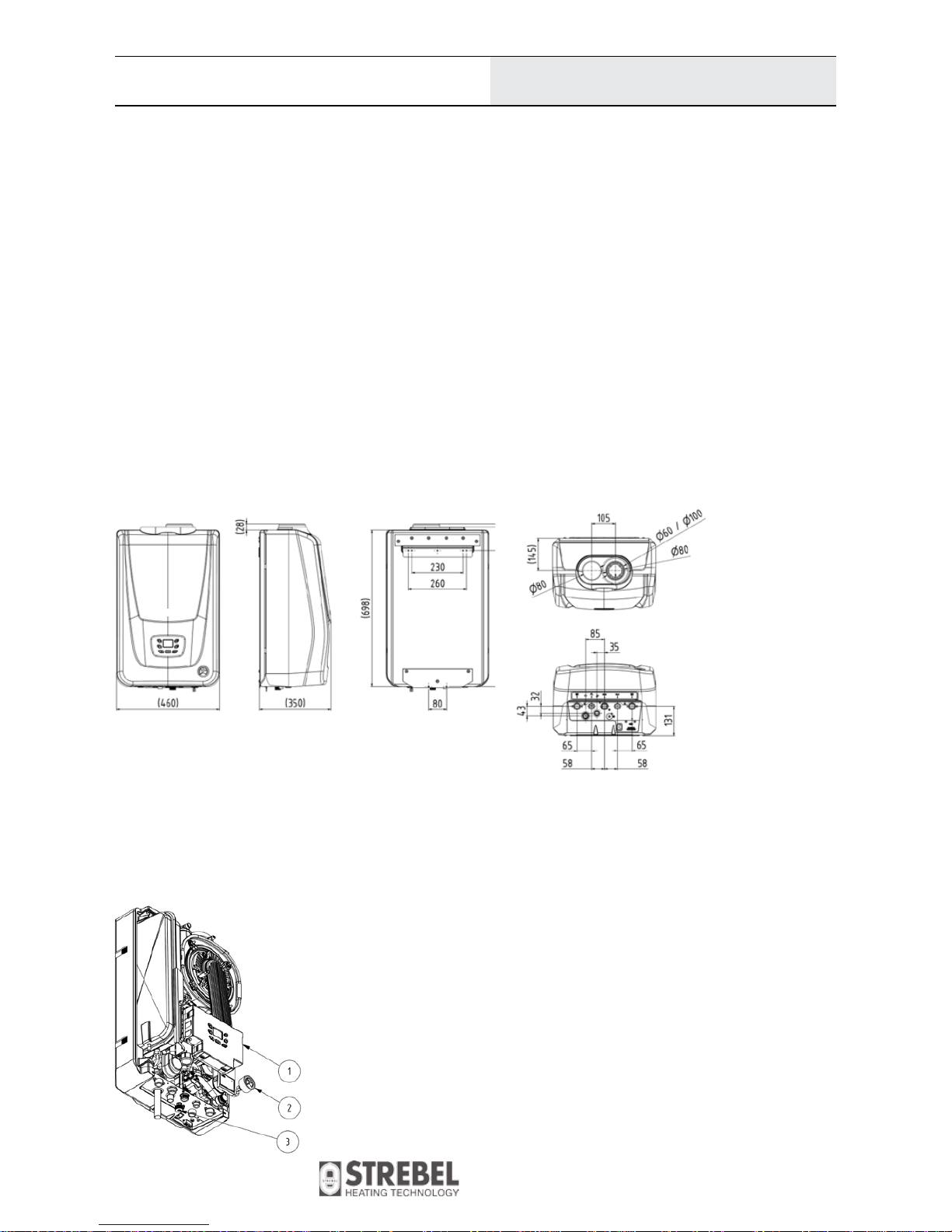
4.2 Dimensions
General Information
4 Boiler Description
4.1 Boiler Design
The boiler elementary structure consists in a condensing exchanger made of stainless steel pipes. It is checked for tightness by test
overpressure 5 bar. The boiler is further equipped with a premix burner. The combustion mixture is mixed in a mixer in the preset air-gas ratio
within the entire output range. Air is supplied to the mixer by a modulation fan.
The boiler is made in three versions:
VIADRUS K4G1HXXXX version designed for heating only is equipped with a circulation pump
VIADRUS K4G2HXXXX version with a circulation pump and flow type hot water (hereafter referred to as “DHW”) heater
VIADRUS K4G3HXXXX version with a circulation pump and a three-way valve ready to be used in combination with a reservoir type hot
water heater
The Honeywell automatics is an electronic control and ignition automatics designed for gas-fired central heating boilers with a modulated fan
and burner with preliminary mixing.
The combustion air inlet and the flue gas outlet may be implemented by several means as follows:
- to the chimney,
- through the wall,
- through the roof (either inclined or horizontal),
- to a joint shaft.
The boiler is an appliance in version C, i.e., a closed appliance with electronic ignition and flame ionization.
4.2 Control Features
1 electronic panel with the control panel
2 pressure gauge
3 valve for adding water to the heating system
19
Boiler Design
K4
Changes in models reserved.
Dimensions not binding!
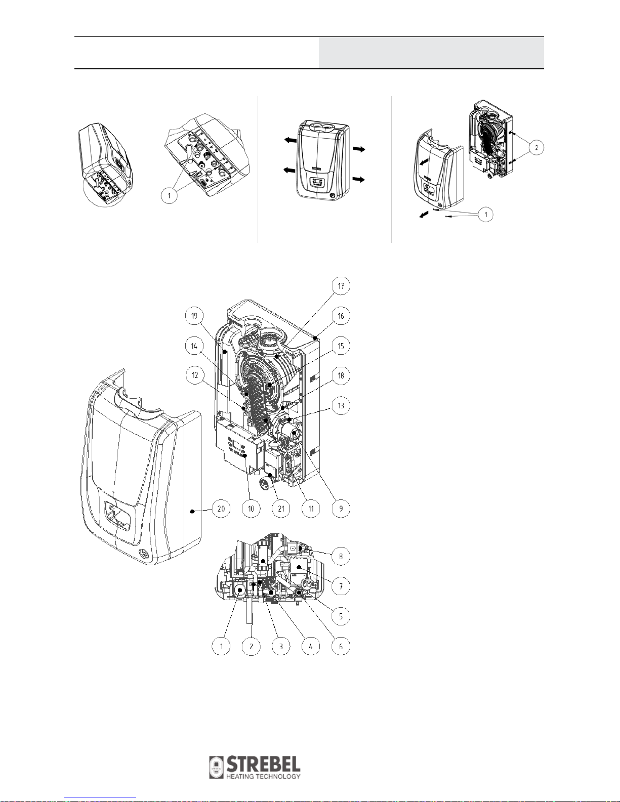
Legend
1. Three way valve (only for models
K4G2H.. and K4G3H..)
2. HWS temperature sensor
(only for models K4G2H..)
3. HWS plate heat exchanger
(only for models K4G2H..)
4. Gas valve
5. Condensation trap
6. Safety valve
7. Circulation pump
8. Gas supply pipe
9. Bleeder valve
10. Boiler control unit
11. Burner plate
12. Heating water temperature sensor
13. Venturi
14. Safety thermostat
15. Electrode
16. Boiler frame
17. Stainless Steel heat exchanger
18. Fan
19. Expansion vessel
20. Pressure gauge
21. Boiler cover
General Information
4 Boiler Description
4.1 Boiler Design
The boiler elementary structure consists in a condensing exchanger made of stainless steel pipes. It is checked for tightness by test
overpressure 5 bar. The boiler is further equipped with a premix burner. The combustion mixture is mixed in a mixer in the preset air-gas ratio
within the entire output range. Air is supplied to the mixer by a modulation fan.
The boiler is made in three versions:
VIADRUS K4G1HXXXX version designed for heating only is equipped with a circulation pump
VIADRUS K4G2HXXXX version with a circulation pump and flow type hot water (hereafter referred to as “DHW”) heater
VIADRUS K4G3HXXXX version with a circulation pump and a three-way valve ready to be used in combination with a reservoir type hot
water heater
The Honeywell automatics is an electronic control and ignition automatics designed for gas-fired central heating boilers with a modulated fan
and burner with preliminary mixing.
The combustion air inlet and the flue gas outlet may be implemented by several means as follows:
- to the chimney,
- through the wall,
- through the roof (either inclined or horizontal),
- to a joint shaft.
The boiler is an appliance in version C, i.e., a closed appliance with electronic ignition and flame ionization.
4.2 Control Features
Fig. №. 2 The VIADRUS K4 boiler control panel
4.2.1 Removing the front cover
• Remove the bolts (1)
• Pulling the cover side detach
the Velcro strip (2)
• Remove the front cover
1 electronic panel with the control panel
2 pressure gauge
3 valve for adding water to the heating system
4.4 Removing The Front Cover
4.5 Main Boiler Parts
20
Boiler Design
 Loading...