

Strebel Geneva C3, Geneva C4, Geneva C5, Geneva C6, Geneva C7 Installation, Operating And Maintenance Manual
...
STREBEL
GENEVA CE
ATMOSPHERIC GAS BOILER
INSTALLATION, OPERATING AND
MAINTENANCE MANUAL

INDEX
TABLE 1 TECHNICAL DATA
SECTION 1 GENERAL
SECTION 2 LOCATION
SECTION 3 VENTILATION
SECTION 4 GAS SUPPLY
SECTION 5 FLUE SYSTEM
SECTION 6 WATER CIRCULATION SYSTEM
SECTION 7 ELECTRICAL SUPPLY
SECTION 8 INSTALLATION
SECTION 9 COMMISSIONING AND TESTING
SECTION 10 SERVICING
SECTION 11 FAULT FINDING
FIGURE 1 CONTROL PANEL LAYOUT
FIGURE 2 NOVA SIT 822 GAS VALVE
FIGURE 3 ELEKTROGAS VM-L GAS VALVE
FIGURE 4 LPG CONVERSION
2
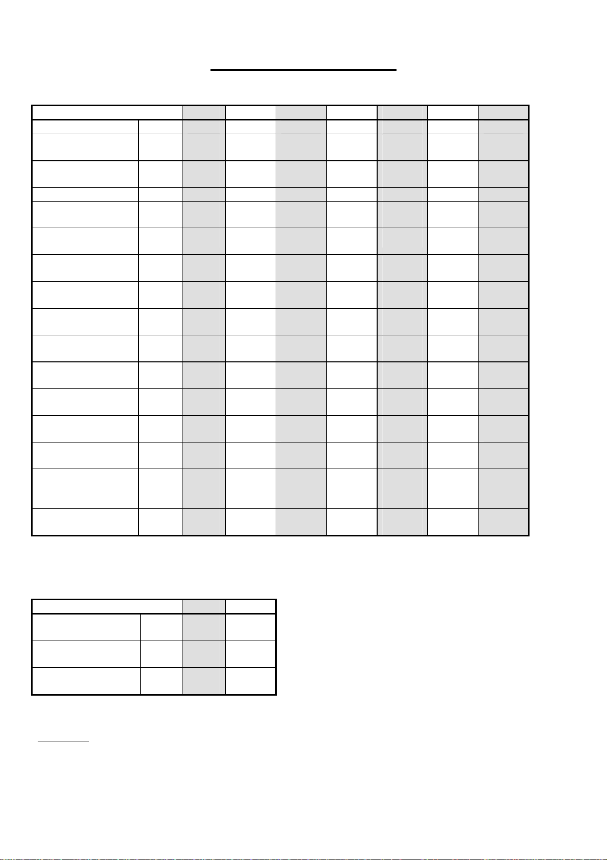
TECHNICAL DATA
BOILER MODEL C3 C4 C5 C6 C7 C8 C9
Number Of Sections 3 4 5 6 7 8 9
Input
Output
Water Content Lits 10 12.5 15 17.5 20 22.5 25
Maximum Working
Pressure
Maximum Working
Temperature
Flow Rate 10°C
Differential
Water Resistance
10°C Differential
Gas Consumption
Natural
Gas Consumption
LPG
Burner Pressure
Natural
Supply Pressure
Natural
Burner Pressure
LPG
Supply Pressure
LPG
Main Injectors
Natural
LPG
Shipping Weight
kW
Btu/hr
kW
Btu/hr
Bar
Psi
°C
Lt/sec
M³/h
mbar
in Wg
M³/h
Ft³/h
Kg/h
Lbs/h
mbar
in Wg
mbar
in Wg
mbar
in Wg
mbar
in Wg
mm
mm
Kg
Lbs
21.4
73,017
19.3
65,852
4
58
90 90 90 90 90 90 90
0.47
1.70
9.5
3.7
2.0
70.21
1.54
3.40
14.8
5.8
18
7
31.8
12.5
37
14.5
2.6
1.75
87
192
31.7
108,160
28.6
97,583
4
58
0.71
2.55
20
7.8
2.9
104.00
2.29
5.04
14.5
5.7
18
7
30.8
12.1
37
14.5
2.6
1.75
110
243
42
143,304
37.7
128,632
4
58
0.95
3.42
36.5
14.4
3.9
137.79
3.03
6.68
13.2
5.2
18
7
30.3
11.9
37
14.5
2.7
1.75
136
300
52.3
178,448
47.1
160,705
4
58
1.10
3.96
23
9.1
4.9
171.58
3.77
8.31
14.5
5.7
18
7
29.7
11.8
37
14.5
2.6
1.75
164
362
62.7
213,932
56.5
192,778
4
58
1.40
5.04
34
13.4
5.8
205.70
4.52
9.97
14.5
5.7
18
7
29.4
11.6
37
14.5
2.6
1.75
186
410
73.7
251,464
66.4
226,557
4
58
1.60
5.76
46
18.1
6.8
241.79
5.31
11.71
14.5
5.7
18
7
29.1
11.4
37
14.5
2.6
1.75
213
470
83.8
285,926
75.6
257,947
4
58
1.90
6.84
57
22.6
7.8
274.93
6.04
13.32
14.5
5.7
18
7
31
12.2
37
14.5
2.6
1.65
234
516
Geneva ‘PV’ as above with these changes.
BOILER MODEL ‘PV’ PV 3 PV 4
Maximum Working
Pressure
Expansion Vessel
Capacity
Shipping Weight
Bar
Psi
Lits
Gal
Kg
Lbs
3
44
8
1.76
94
207
2.20
118
260
TABLE. 1
3
44
10
3

INSTALLATION INSTRUCTIONS
1.0 GENERAL
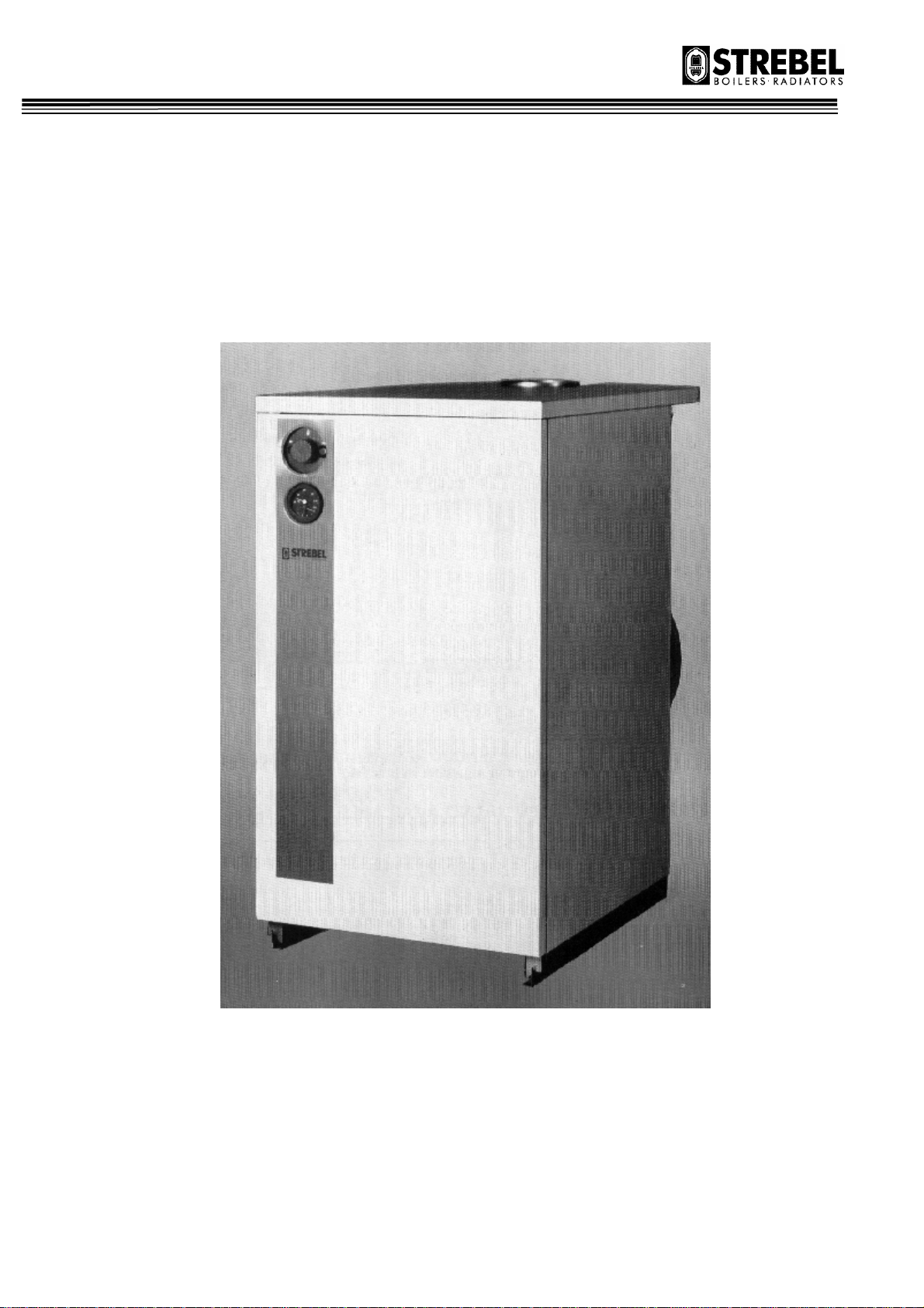
1.1 The STREBEL GENEVA ‘PV’ & ‘C’ range of Gas Fired Boilers are floor mounted open flued units for
connection to indirect heating and hot water systems.
The Geneva heat exchanger body is constructed of cast iron sections with a stainless steel atmospheric gas
burner suitable for Natural Gas and LPG (site conversion) the boilers as standard are fitted with electronic
ignition. The boilers are fitted with full safety devices including “Spillage Control System” (SCS) which
shuts down the boiler if Spillage is occurring and so prevents any escape of flue gases out the flue diverter,
also on the C60 & C68 models there is a Gas pressure switch for low gas inlet pressure.
The boilers are delivered completely assembled jackets fitted and fully insulated.
The Geneva ‘PV’ range is also fitted with three speed circulating pump, expansion vessel for use with a
sealed systems, 3 Bar safety valve, pressure gauge and water fill point (manual).
1.2 The installation of this boiler must be carried out in accordance with the relevant requirements of the gas
safety (installation and use) Regulations 1984, the I.E.E. Wiring Regulations and the Bylaws of the Local
Water Undertaking, and the Building Regulations 1985.
Detailed recommendations are contained in the following:
British Standard Code of Practice CP. 341 : 300-307 ; CP 342 : Parts I and 2 : BS. 5440 parts 1 & 2 :
BS.5854 : BS. 6644 :BS. 6798 : BS. 6891 and British Gas Publications :- IM/11 Flues for Commercial and
Industrial Gas Fired Boilers an Air Heaters
"The Gas Safety (Installation and Use) Regulations 1984:
It is the law that all gas appliances are installed by CORGI registered contractors in accordance with the
above regulations. Failure to install appliances correctly could lead to prosecution. It is in your own
interest, and that of safety, to ensure that the law is complied with".
2.0 LOCATION
2.1 The boiler must stand on a level non combustible base, which is capable of adequately supporting the weight
of the boiler, water content an any ancillary equipment.
The location chosen for the boiler must permit the provision of a satisfactory flue and termination.
The location must also permit an adequate space for combustion and ventilation purposes (see Section 3 on
Ventilation) and adequate space for servicing and air circulation around the boiler.
3.0 VENTILATION
3.1 It is important that there are sufficient areas of air inlet and ventilation provided to the boiler room detail
recommendations for air supply are given in BS. 5440 part 2 & BS. 6644. The following notes are intended
to give general guidance.
3.2 Natural Ventilation.
Where both low- and high-level openings are used, the grilles shall have a total minimum free area as
follows:
Low level (inlet): 540 cm² plus 4.5 cm² per Kilowatt in excess of 60 kW total rated input;
High level (inlet): 270 cm² plus 2.25 cm² per Kilowatt in excess of 60 kW total rated input.
4

3.3 Mechanical Ventilation.
The minimum quantity of air required for combustion and boiler house ventilation shall be supplied at a
minimum flow rate in accordance with BS. 6644.
All air inlet and extract fans shall be fitted with automatic controls causing safety shut-down or lockout of
the boiler(s) in the event of the inlet or extract air flow failing.
4.0 GAS SUPPLY
4.1 An existing meter should be checked preferably by the Gas Supplier, to ensure the meter is adequate to deal
with the rate of gas required.
4.2 Pipework from the meter to the boiler must be of adequate size. Pipes of smaller size than the boiler inlet gas
connection should not be used. All gas pipework should be fitted and on completion of installation tested, in
accordance with BS. 6891 : IGE/UP/2 Gas Installation Pipework, Boosters and Compressors on Industrial
and Commercial Premises.
4.3 Gas supply connections is as follows:
Geneva PV 3 & PV 4 = 1/2" BSP
Geneva C 3, C 4, C 5, C 6 & C 7 = 1/2" BSP
Geneva C 8 & C 9 = 1" BSP.
4.4 A gas service cock must be fitted immediately adjacent to the boiler.
5.0 FLUE SYSTEM
5.1 Detail recommendations for flueing are given in B.G.C. Publications:- “Flues for commercial and Industrial
Gas Fired Boilers and Air Heaters” 1M/11.
Reference should also be made to BS. 5440 Part 1 : BS. 6644 where applicable.
The following notes are intended to give general guidance.
5.2 The nominal flue size should not be less than that of the boiler flue connection, and must be at least
equivalent to a vertical height above the boiler outlet of 1 M (3 ft 3 in), due allowance being made for any
horizontal or inclined length, and consideration being given to the position of the outlet.
The boiler flue hood is not load bearing and the flue must be supported independently. The flue should be
easily disconnected for servicing.
6.5 WATER CIRCULATION SYSTEM
6.1 Flow and return connections are from the back of the boiler with BSP connections.
6.2 In combined heating and hot water systems the hot water storage vessel must be of the indirect cylinder or
calorifier type.
6.3 The boiler maximum working pressure is 3 Bar (43.5 Psi) for ‘PV’ models and 4 Bar (58 Psi) for ‘C’ models
which includes pump circulation head. The minimum head being 1 meter above the top of the boiler.
6.5 Hydraulic Resistance and Flow Rates
The differential temperatures across the flow and return water connections to the boiler is recommend as
10°C temperature difference (Max. temperature difference 20°C).
Water flow rates and water pressure drops across the boilers are detailed on Table 1.
6.6 If three-way mixing or diverting vales are installed in the systems they should not be of such a type that the
flow through the boiler is totally closed. If such valves are used, a by-pass should be fitted.
5
 Loading...