

Strebel CIS, CISM Installation Instructions Manual
STREBEL CIS BOILERS
BOILER INSTALLATION INSTRUCTIONS FOR STREBEL CISM BOILERS
INSTALLATION INSTRUCTIONS
General Instructions:
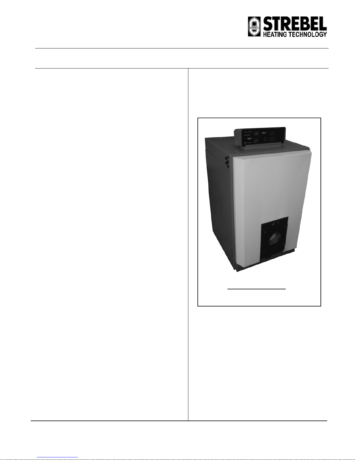
The STREBEL CIS & CIS boilers are special boilers for light oil or gasfired (forced) burners. They can be fitted in hot water heating
installations or low pressure steam installations, depending on the type.
Operating Conditions:
Hot water Heating installations boiler type STREBEL CIS
STREBEL CISM
Maximum high limit temperature 110ºC
Maximum Operating Temperature 95°C
Maximum working pressure 4 bar
Please note all relevant instructions when assembling the boilers.
The Installation: The connecting and initial setting in operation should
be carried out by a qualified heating specialist.
The boiler base is to be constructed in accordance with our diagrams.
Advantages of the STREBEL CIS AND CISM:
1. Long life of cast iron boiler body.
2. High efficiency of operation. Efficiency of combustion is higher
than 90.5 % for all kinds of fuels.
3. Possibility of delivery with burner.
4. Modern design.
5. Signalling of operation and defect of boiler.
6. It is possible to order a special variation of the boiler allowing a
water temperature of 115ºC (standard delivery is with boiler
water temperature up to 95ºC).
7. The ability to use a modular arrangement of connection.
8. Delivery fully assembled or in part form according to customer
requirements is available.
9. Door can be mounted to swing from either side (must be
specified in order).
10. Easily visible sight glass for viewing flame or for reading
combustion chamber pressure.
STREBEL CIS BOILER
V.1 - 03.08
STREBEL CIS
ASSEMBLY INSTRUCTIONS FOR: STREBEL CIS
Page 2
V.1-03.08
INDEX : PAGE
ASSEMBLY TOOLS 3
BOILER BASE 3
TECHNICAL DATA 4 & 5
BOILER ERECTION
WALL CLEARANCES 6
COMPONENTS REQUIRED 6
IMPORTANT ASSEMBLY ADVISE 7
BOILER ASSEMBLY
BOILER BLOCK 8 & 9
FIXTURES 10
BURNER DOOR 10
UPPER FLUE-WAY DOOR 10
BOILER JACKETS 10
FLUE HOOD 10
FLOW AND RETURN CONNECTIONS 10
INSTRUMENT CONTROL PANEL ASSEMBLY
DESCRIPTION OF INSTRUMENT CONTROL PANEL 12
ASSEMBLING THE BURNER 12
INSTRUMENT CONTROL PANEL WIRING DIAGRAM 13
INSTRUMENT CONTROL PANEL TERMINAL DIAGRAM 14
BEFORE STARTING BOILER / BURNER 15
FAULT FINDING 15
MAINTENANCE 15
HAZARDS 15
STREBEL CIS
ASSEMBLY INSTRUCTIONS FOR: STREBEL CIS
Page 3
V.1-03.08
ASSEMBLY TOOL
A bar Pulling up tool, which is returnable after assembly has been successfully
completed, is made available for assembling the boiler block.
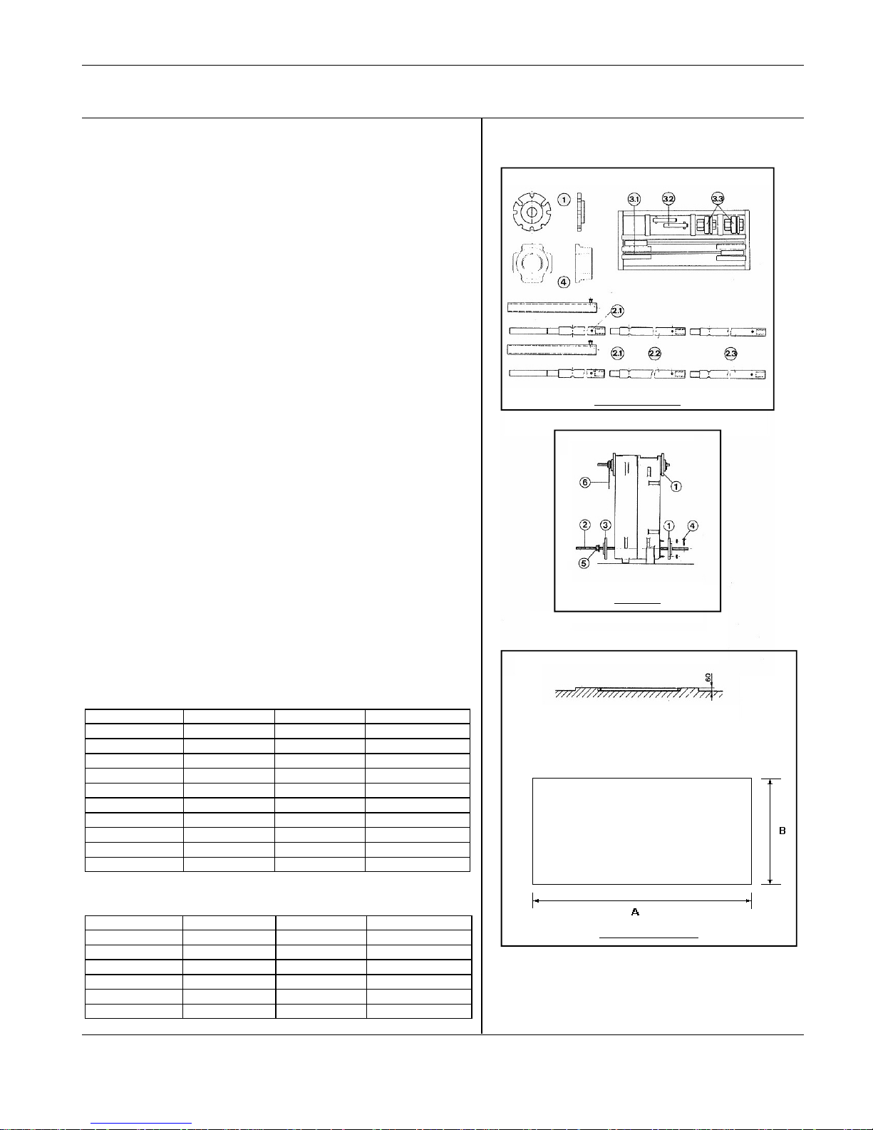
The complete pulling up kit CIS/CISM consists of the following:
1) Pulling up flange at the top rear section
1) Pulling up flange at the bottom rear section
1) Pulling up flange at the intermediate section
1) Pulling up flange at the bottom front section
4) Pulling up flange at the top front section
5) Pulling up piping
2.1) Basic bar
2.2) Extension
2.3) End piece
Case containing press tool
3.1) Free running ratchet spanner
3.2) Stop pins
3.3) Pulling up nut with thrust bearing
Items needed for construction: flat chisel, mallet, brush, small round smoothing
file, emery cloth, cleanser (e.g. petroleum), inspection lamp, spanner.
Advice on the use of the pulling-up tools.
1) The pulling up flanges at the rear section are screwed onto the boiler flow
and return connections.
2) The basic bars are inserted through the openings of the press flanges and
ports so that the screw ends are situated out of the ports at the front. (The
basic bars can be extended, as necessary.)
3) The pulling up flanges at the intermediate section or front section are pushed
over the basic bar screw end from the front.
4) The Stop pins are inserted at the back through one of the transverse borings
of the pulling up bar.
5) The pulling up nuts are screwed onto the basic bar screw end, from the front
until they take up the slack on the pulling up tool flanges.
6) The free-running ratchet spanners are put on the starting nuts.
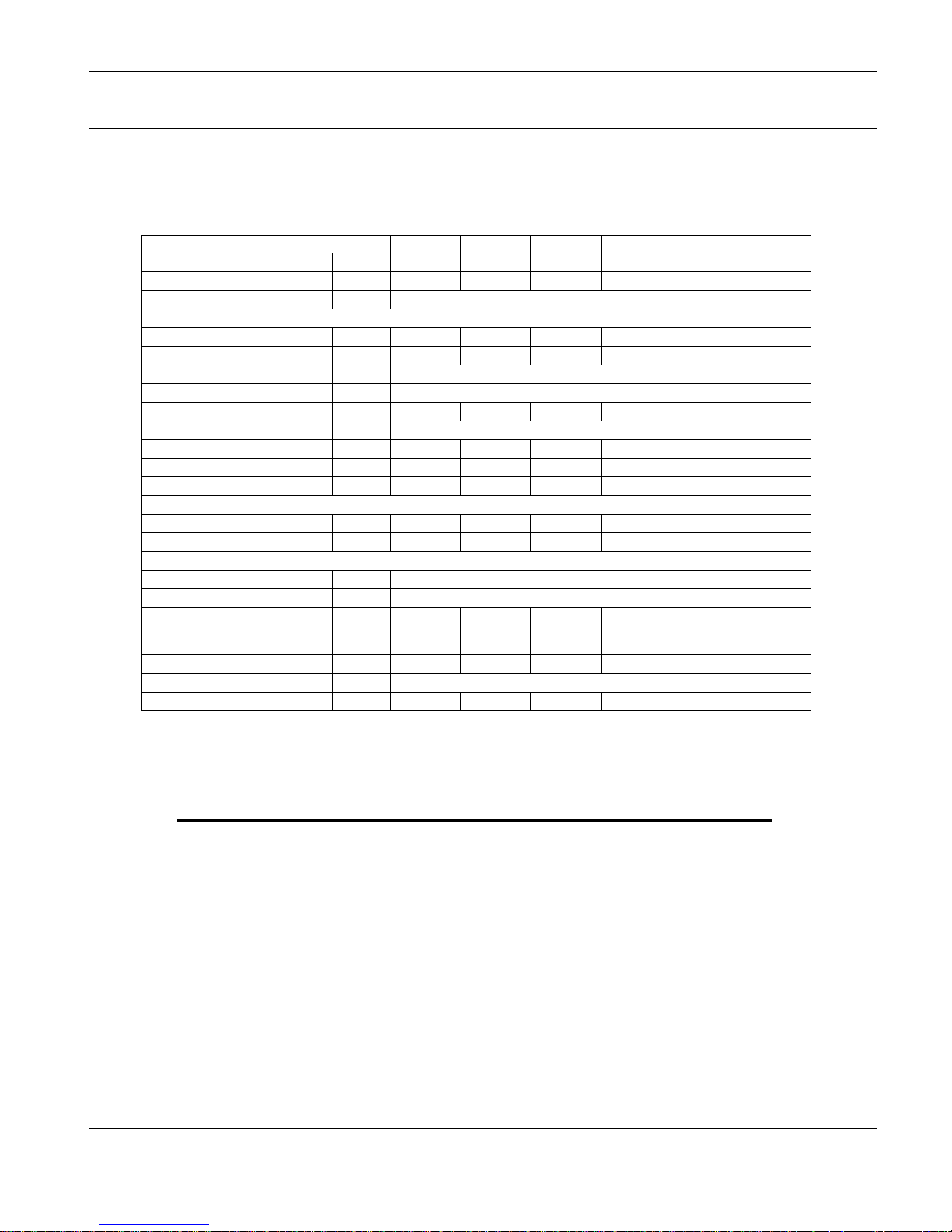
Boiler base
The boiler base is to be constructed in accordance with our base plans. The boiler
block may stand on an iron frame set in concrete. The boiler base must stand on a
level, non combustable base which is capable of supporting the weight of the
boiler, water content and any ancillary equipment. These dimensions provide a
50mm excess around the boiler jackets.
STREBEL CIS
ASSEMBLY INSTRUCTIONS FOR STREBEL CISM
STREBEL CISM
No. of sections Width (B) (mm) Length (A) (mm) Min. Thickness (mm)
10 904 1862 60
11 904 2012 60
12 904 2162 60
13 904 2312 60
14 904 2462 60
15 904 2612 60
STREBEL CIS
No. of sections Width (B) (mm) Length (A) (mm) Min.Thickness (mm)
5 850 860 60
6 850 970 60
7 850 1080 60
8 850 1190 60
9 850 1300 60
10 850 1410 60
11 850 1520 60
12 850 1630 60
13 850 1740 60
14 850 1850 60
Pulling-up tools
Boiler base details
Tool use
STREBEL CIS
ASSEMBLY INSTRUCTIONS FOR: STREBEL CIS
Page 4
V.1-03.08
S
T
R
E
B
E
L
C
I
S
–
T
E
C
H
N
I
C
A
L
D
A
T
A
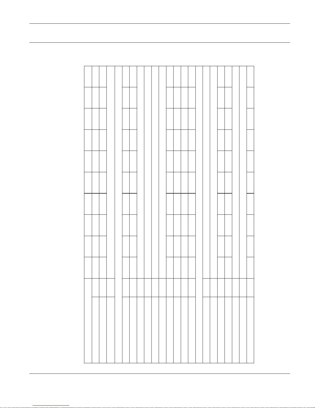
No. of Sections
5 6 7 8 9 10 11 12 13 14
Nominal Output kW 103 126 149 172 195 218 241 264 287 310
Nominal Input kW 113.2 138.5 163.7 189 214.3 239.6 264.8 290.1 315.4 340.7
Efficiency % 90.5
Fuel Consumption:
Natural Gas m³/hr 11.5 14.1 16.7 19.3 21.9 24.5 27.1 29.7 32.2 34.9
Extra Light Heating Oil kg/hr 9.59 11.74 13.87 16.02 18.16 20.31 22.44 24.58 26.73 28.87
Max. Working Pressure bar 4
Max. Boiler Operating Temp. ºC 90
Combustion Chamber Pressure mbar 2
Approx. Flue Gas Temp. ºC 185
Flue Gas Volume kg/sec 0.053 0.065 0.077 0.088 0.100 0.112 0.124 0.136 0.148 0.149
Water Volume of Boiler litres 56.4 65.4 74.4 83.4 92.4 101.4 110.4 119.4 128.4 137.4
Combustion Chamber Volume cm³ 81.79 100.73 119.68 138.62 157.56 176.51 195.45 214.39 233.33 252.27
Hydraulic Resistance @ 10°C ∆ T mbar 0.20 0.24 0.25 0.31 0.37 0.43 0.50 0.55 0.63 0.71
Dimensions:
Height mm 1355
Width mm 750
Depth mm 737 847 957 1067 1177 1287 1397 1507 1617 1717
Depth of Combustion Chamber mm 475 585 695 805 915 1025 1135 1245 1355 1465
Flue Spigot Diameter mm 225
Flow & Return Connections mm 80
Weight of Boiler kg 505 585 665 745 825 905 985 1065 1145 1225
STREBEL CIS
ASSEMBLY INSTRUCTIONS FOR: STREBEL CIS
Page 5
V.1-03.08
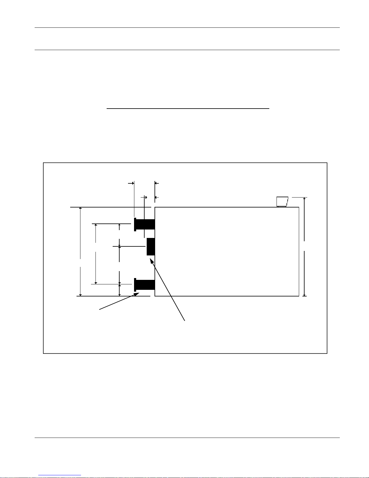
STREBEL CIS Series - Connection Dimensions
1185mm
125mm
Flue spigot 220mm
outside diameter
Flow & Return connections
80mm I.d pipe
Mating weldneck flanges
supplied
STREBEL CIS BOILER
80mm
275mm
670mm
95mm
945mm
1355mm
STREBEL CIS
ASSEMBLY INSTRUCTIONS FOR: STREBEL CIS
Page 6
V.1-03.08
STREBEL CISM – TECHNICAL DATA
No. of Sections
10 11 12 13 14 15
Nominal Output kW 330 400 470 550 620 690
Nominal Input kW 360 438 512 600 678 754
Efficiency % 91.5
Fuel Consumption:
Natural Gas m³/hr 36.1 43.9 51.4 60.2 71.1 82.3
Extra Light Heating Oil kg/hr 30.2 36.8 43.1 50.5 58.0 65.5
Max. Working Pressure bar 4
Max. Boiler Operating Temp. ºC 90
Combustion Chamber Pressure mbar 0.9 1.4 2.2 3.2 5 6.2
Approx. Flue Gas Temp. ºC 165 - 190
Flue Gas Volume kg/sec 0.088 0.100 0.120 0.135 0.156 0.180
Water Volume of Boiler litres 252 277 302 327 352 377
Combustion Chamber Volume cm³ 314 347 381 414 449 485
Hydraulic Resistance
@ 20°C ∆ T mbar 0.90 1.35 1.90 2.60 3.34 4.20
@ 10°C ∆ T mbar 3.40 3.90 5.30 8.60 12.40 16.70
Dimensions:
Height mm 1237
Width mm 904
Depth mm 1762 1912 2062 2212 2362 2512
Depth of Combustion Chamber mm 1377 1527 1677 1827 1977 2127
Flue Spigot Diameter mm 250 250 250 300 300 300
Flow & Return Connections mm 100
Weight of Boiler kg 1660 1815 1970 2125 2280 2435
 Loading...