

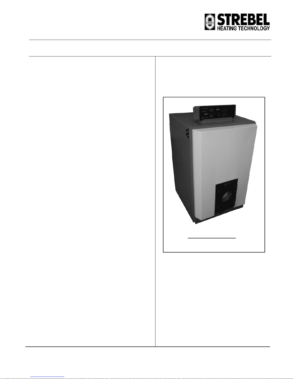
STREBEL CIS BOILERS
BOILER INSTALLATION INSTRUCTIONS FOR STREBEL CISM BOILERS
INSTALLATION INSTRUCTIONS
General Instructions:
The STREBEL CIS & CIS boilers are special boilers for light oil or gasfired (forced) burners. They can be fitted in hot water heating
installations or low pressure steam installations, depending on the type.
Operating Conditions:
Hot water Heating installations boiler type STREBEL CIS
STREBEL CISM
Maximum high limit temperature 110ºC
Maximum Operating Temperature 95°C
Maximum working pressure 4 bar
Please note all relevant instructions when assembling the boilers.
The Installation: The connecting and initial setting in operation should
be carried out by a qualified heating specialist.
The boiler base is to be constructed in accordance with our diagrams.
Advantages of the STREBEL CIS AND CISM:
1. Long life of cast iron boiler body.
2. High efficiency of operation. Efficiency of combustion is higher
than 90.5 % for all kinds of fuels.
3. Possibility of delivery with burner.
4. Modern design.
5. Signalling of operation and defect of boiler.
6. It is possible to order a special variation of the boiler allowing a
water temperature of 115ºC (standard delivery is with boiler
water temperature up to 95ºC).
7. The ability to use a modular arrangement of connection.
8. Delivery fully assembled or in part form according to customer
requirements is available.
9. Door can be mounted to swing from either side (must be
specified in order).
10. Easily visible sight glass for viewing flame or for reading
combustion chamber pressure.
STREBEL CIS BOILER
V.1 - 03.08

STREBEL CIS
ASSEMBLY INSTRUCTIONS FOR: STREBEL CIS
Page 2
V.1-03.08
INDEX : PAGE
ASSEMBLY TOOLS 3
BOILER BASE 3
TECHNICAL DATA 4 & 5
BOILER ERECTION
WALL CLEARANCES 6
COMPONENTS REQUIRED 6
IMPORTANT ASSEMBLY ADVISE 7
BOILER ASSEMBLY
BOILER BLOCK 8 & 9
FIXTURES 10
BURNER DOOR 10
UPPER FLUE-WAY DOOR 10
BOILER JACKETS 10
FLUE HOOD 10
FLOW AND RETURN CONNECTIONS 10
INSTRUMENT CONTROL PANEL ASSEMBLY
DESCRIPTION OF INSTRUMENT CONTROL PANEL 12
ASSEMBLING THE BURNER 12
INSTRUMENT CONTROL PANEL WIRING DIAGRAM 13
INSTRUMENT CONTROL PANEL TERMINAL DIAGRAM 14
BEFORE STARTING BOILER / BURNER 15
FAULT FINDING 15
MAINTENANCE 15
HAZARDS 15
STREBEL CIS
ASSEMBLY INSTRUCTIONS FOR: STREBEL CIS
Page 3
V.1-03.08
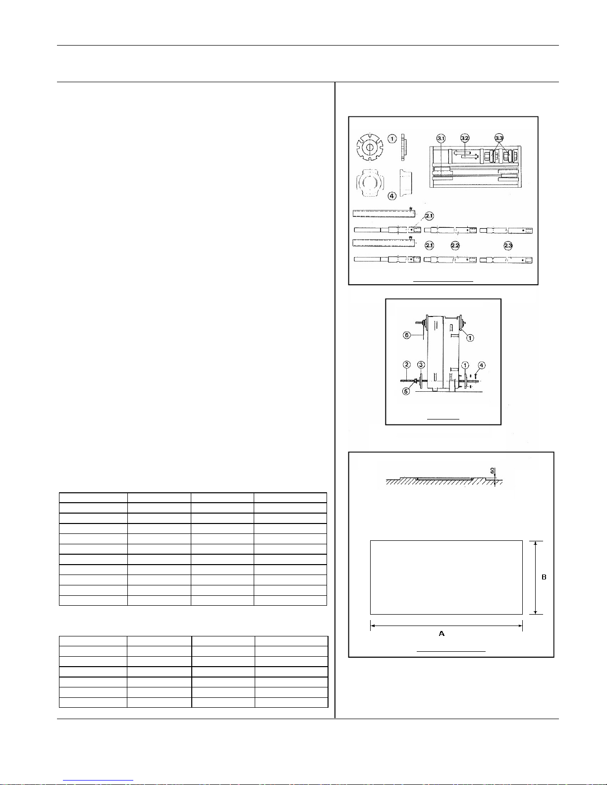
ASSEMBLY TOOL
A bar Pulling up tool, which is returnable after assembly has been successfully
completed, is made available for assembling the boiler block.
The complete pulling up kit CIS/CISM consists of the following:
1) Pulling up flange at the top rear section
1) Pulling up flange at the bottom rear section
1) Pulling up flange at the intermediate section
1) Pulling up flange at the bottom front section
4) Pulling up flange at the top front section
5) Pulling up piping
2.1) Basic bar
2.2) Extension
2.3) End piece
Case containing press tool
3.1) Free running ratchet spanner
3.2) Stop pins
3.3) Pulling up nut with thrust bearing
Items needed for construction: flat chisel, mallet, brush, small round smoothing
file, emery cloth, cleanser (e.g. petroleum), inspection lamp, spanner.
Advice on the use of the pulling-up tools.
1) The pulling up flanges at the rear section are screwed onto the boiler flow
and return connections.
2) The basic bars are inserted through the openings of the press flanges and
ports so that the screw ends are situated out of the ports at the front. (The
basic bars can be extended, as necessary.)
3) The pulling up flanges at the intermediate section or front section are pushed
over the basic bar screw end from the front.
4) The Stop pins are inserted at the back through one of the transverse borings
of the pulling up bar.
5) The pulling up nuts are screwed onto the basic bar screw end, from the front
until they take up the slack on the pulling up tool flanges.
6) The free-running ratchet spanners are put on the starting nuts.
Boiler base
The boiler base is to be constructed in accordance with our base plans. The boiler
block may stand on an iron frame set in concrete. The boiler base must stand on a
level, non combustable base which is capable of supporting the weight of the
boiler, water content and any ancillary equipment. These dimensions provide a
50mm excess around the boiler jackets.
STREBEL CIS
ASSEMBLY INSTRUCTIONS FOR STREBEL CISM
STREBEL CISM
No. of sections Width (B) (mm) Length (A) (mm) Min. Thickness (mm)
10 904 1862 60
11 904 2012 60
12 904 2162 60
13 904 2312 60
14 904 2462 60
15 904 2612 60
STREBEL CIS
No. of sections Width (B) (mm) Length (A) (mm) Min.Thickness (mm)
5 850 860 60
6 850 970 60
7 850 1080 60
8 850 1190 60
9 850 1300 60
10 850 1410 60
11 850 1520 60
12 850 1630 60
13 850 1740 60
14 850 1850 60
Pulling-up tools
Boiler base details
Tool use

STREBEL CIS
ASSEMBLY INSTRUCTIONS FOR: STREBEL CIS
Page 4
V.1-03.08
S
T
R
E
B
E
L
C
I
S
–
T
E
C
H
N
I
C
A
L
D
A
T
A
No. of Sections
5 6 7 8 9 10 11 12 13 14
Nominal Output kW 103 126 149 172 195 218 241 264 287 310
Nominal Input kW 113.2 138.5 163.7 189 214.3 239.6 264.8 290.1 315.4 340.7
Efficiency % 90.5
Fuel Consumption:
Natural Gas m³/hr 11.5 14.1 16.7 19.3 21.9 24.5 27.1 29.7 32.2 34.9
Extra Light Heating Oil kg/hr 9.59 11.74 13.87 16.02 18.16 20.31 22.44 24.58 26.73 28.87
Max. Working Pressure bar 4
Max. Boiler Operating Temp. ºC 90
Combustion Chamber Pressure mbar 2
Approx. Flue Gas Temp. ºC 185
Flue Gas Volume kg/sec 0.053 0.065 0.077 0.088 0.100 0.112 0.124 0.136 0.148 0.149
Water Volume of Boiler litres 56.4 65.4 74.4 83.4 92.4 101.4 110.4 119.4 128.4 137.4
Combustion Chamber Volume cm³ 81.79 100.73 119.68 138.62 157.56 176.51 195.45 214.39 233.33 252.27
Hydraulic Resistance @ 10°C ∆ T mbar 0.20 0.24 0.25 0.31 0.37 0.43 0.50 0.55 0.63 0.71
Dimensions:
Height mm 1355
Width mm 750
Depth mm 737 847 957 1067 1177 1287 1397 1507 1617 1717
Depth of Combustion Chamber mm 475 585 695 805 915 1025 1135 1245 1355 1465
Flue Spigot Diameter mm 225
Flow & Return Connections mm 80
Weight of Boiler kg 505 585 665 745 825 905 985 1065 1145 1225
STREBEL CIS
ASSEMBLY INSTRUCTIONS FOR: STREBEL CIS
Page 5
V.1-03.08
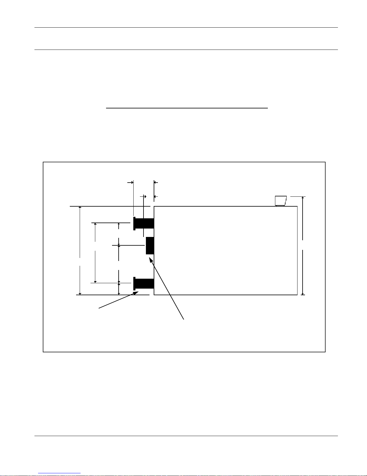
STREBEL CIS Series - Connection Dimensions
1185mm
125mm
Flue spigot 220mm
outside diameter
Flow & Return connections
80mm I.d pipe
Mating weldneck flanges
supplied
STREBEL CIS BOILER
80mm
275mm
670mm
95mm
945mm
1355mm
STREBEL CIS
ASSEMBLY INSTRUCTIONS FOR: STREBEL CIS
Page 6
V.1-03.08
STREBEL CISM – TECHNICAL DATA
No. of Sections
10 11 12 13 14 15
Nominal Output kW 330 400 470 550 620 690
Nominal Input kW 360 438 512 600 678 754
Efficiency % 91.5
Fuel Consumption:
Natural Gas m³/hr 36.1 43.9 51.4 60.2 71.1 82.3
Extra Light Heating Oil kg/hr 30.2 36.8 43.1 50.5 58.0 65.5
Max. Working Pressure bar 4
Max. Boiler Operating Temp. ºC 90
Combustion Chamber Pressure mbar 0.9 1.4 2.2 3.2 5 6.2
Approx. Flue Gas Temp. ºC 165 - 190
Flue Gas Volume kg/sec 0.088 0.100 0.120 0.135 0.156 0.180
Water Volume of Boiler litres 252 277 302 327 352 377
Combustion Chamber Volume cm³ 314 347 381 414 449 485
Hydraulic Resistance
@ 20°C ∆ T mbar 0.90 1.35 1.90 2.60 3.34 4.20
@ 10°C ∆ T mbar 3.40 3.90 5.30 8.60 12.40 16.70
Dimensions:
Height mm 1237
Width mm 904
Depth mm 1762 1912 2062 2212 2362 2512
Depth of Combustion Chamber mm 1377 1527 1677 1827 1977 2127
Flue Spigot Diameter mm 250 250 250 300 300 300
Flow & Return Connections mm 100
Weight of Boiler kg 1660 1815 1970 2125 2280 2435

STREBEL CIS
ASSEMBLY INSTRUCTIONS FOR: STREBEL CIS
Page 7
V.1-03.08
Boiler erection.
Wall clearances.
There must be free space around the boiler to access the boiler for servicing
purposes. The space in front of the boiler must be of distance equal to 1.5 times
the depth (L).
Access at one side should be a minimum of 500mm allowing free movement to
the rear of the boiler again for servicing purposes.
These areas around the boiler must be kept free from debris, especially, free from
combustible materials.
Components required:
→ Number of sections: front, rear and from 3 to 12 intermediate sections
(according to boiler size).
→ Boiler nipples: 8 to 26 (according to boiler size).
→ Boiler sealing mastic.
→ Nipple jointing oil.
→ Tie bars.
→ Injector.
→ 2 “ Plug
→ 2” x 1/2” bush.
→ Thermometer pocket.
→ Thermostat poket.
→ 1/2” self-closing valve for altitude (pressure) gauge.

STREBEL CIS
ASSEMBLY INSTRUCTIONS FOR: STREBEL CIS
Page 8
V.1-03.08
Important Assembly Advice:
Please read through before starting the assembly!
The boiler is normally delivered in individual sections, which are assembled as a
boiler block by means of tapered nipples.
The watertight joint between two boiler sections is a high-precision press fit
between the boiler nipple and nipple port. The block assembly must be carried
out accordingly with precision.
The following points should be observed during assembly:
No damage to the nipple and borings should be apparent.
Before a nipple is inserted and a section fitted, the nipple and the boring should
be inspected. Any damage, e.g. to the face of the boring, destroys the nipple seal
and leads to leakage.
Attention! Minor damage (transport damage) to the faces of the boiler nipple or
to the nipple ports (A) can be corrected with a small smoothing file and emery
cloth without affecting the water tightness of the joint.
→ The accompanying nipple jointing oil sealing compound serves as a lubri
cant as well as a waterproof seal and must be used.
→ During the assembly no dirt should be allowed to remain on the nipples
or in the boring. These should be inspected during each assembly
phase, but particularly before fixing on the pulling–up flanges. Particles of
dirt, which are not removed, can lead to leakage.
→ During the boiler block assembly take care that the various boiler sec tions are fitted to the various positions, depending on the model.
→ Boiler nipples and nipple ports must align exactly at all stages of the as-
sembly.
→ An inclined inserted nipple leads to leakage.
A boiler section is built on basically in three stages: In addition, certain specific
points should be observed at each stage:
Stage 1: Drive nipple into boring with care
Inspect nipple and boring for damage.
Smear linseed oil sealing compound over nipple and boring. Gently drive nipple
into flow and return nipple ports using a mallet or synthetic hammer. The nipples
must remain firm and exactly vertical in the nipple ports and must be able to take
the next boiler section without twisting from nipple port. Take care, inclined
nipples lead to leakage.
Stage 2: Joining the boiler section to both inserted nipples.
Inspect nipple and nipple port for damage.
Smear linseed oil sealing compound over nipple and nipple port. Cover one
section with boiler mastic sealing strand. Place boiler section in front of both
inserted nipples. Raise the boiler section with the inserted nipples using a flat
chisel at all times under the section feet. The inserted nipples must stand approx.
1 to 2 mm higher than the boring of the section, which is to be joined. Using a
crowbar, raise boiler section to the inserted nipples until nipple and nipple ports
mate and hold.
Inspect boring once again for any dirt deposits before fixing the pulling-up
flanges. Remove dirt deposits if necessary.
Stage 3: To assemble boiler sections using bar pulling-up tool.
Take care during the pulling-up process that the clearance between both boiler
and section is even. If the clearance is uneven insert a flat chisel into the narrow
point and continue pulling-up until the clearance is even again.
Nipples and Nipple ports
Driving in nipple

STREBEL CIS
ASSEMBLY INSTRUCTIONS FOR: STREBEL CIS
Page 9
V.1-03.08
Assembly of the boiler block from individual sections
Starting with the rear section to the front, the boiler block is assembled on the
boiler base.
1. Erect and support the rear section (A).
2. Clean the rear section sealing grooves and place boiler mastic sealing strand
into the sealing grooves.
3. Clean nipple and port. Inspect and smear with nipple jointing oil
4. Drive nipple into flow and return ports
5. Level the first intermediate section onto both rear section nipples.
6. Pull on intermediate section with pulling up tool. Fix on pulling up flanges,
starting nuts and ratchet spanners; tighten the starting nuts evenly (C). The
clearance between the two sections must be equal when pulling-up. If
clearance is unequal insert a flat chisel in the narrower point and continue
pulling-up until clearance is equal again.
Avoid using excessive force
and smooth out excess mastic.
Add on only one section at a time in each case.
Further sections are added accordingly.
7. On completion of the boiler block. Push pulling up bars through the lugs on
the ready assembled boiler block. Slide a flat washer and nut onto the tie
bars at the front and rear respectively and screw on hexagonal nut. Hold fast
one nut and draw on the other nut until tight.
Boiler Block Alignment
Any unevenness between boiler base and section feet can be levelled out by
laying metal shims underneath the boiler section feet.
A
B
C
STREBEL CIS
ASSEMBLY INSTRUCTIONS FOR: STREBEL CIS
Page 10
V.1-03.08
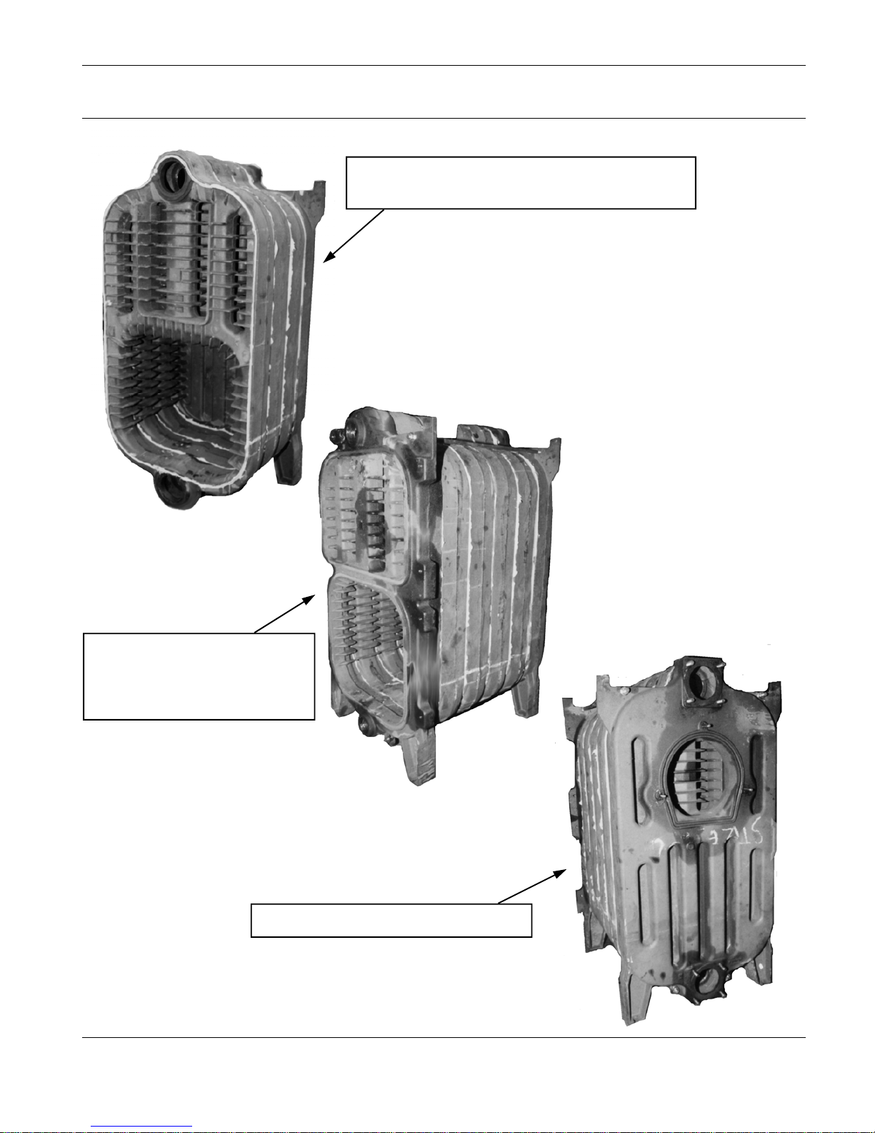
Front view showing the first three intermediate
sections after ‘pulling up’.
Front view showing the
complete boiler block without
the burner door or flue pass
door.
Rear view of the complete boiler block.

STREBEL CIS
ASSEMBLY INSTRUCTIONS FOR: STREBEL CIS
Page 11
V.1-03.08
Assembly of fixtures
1. Fit 2” plug into the bottom tapping on the front section of the boiler (A).
2. Fit the 2” x 1/2” bush to the upper tapping of the boiler front section for the
thermostat pocket (B+C).
3. Next fit the thermostat pocket (1/2” diameter) into the bush (B).
4. Fit the thermometer pocket into the tapping immediately to the right of the self
closing valve (C)
5. Fit the 1/2” self-closing valve for the altitude (pressure) gauge into the upper
left hand tapping (D)
6. Fit the injector into the return connection with joggle to the bottom.
7. Connect flange to the lower return connection.
8. Connect the flow header to the upper tapping of the rear section.
Burner door assembly
1. Attach M12 screw with eye into the tapping on the front section ensuring that
there is a 40mm gap between the centre of the eyelet to the edge of the front
section and tighten locking nut (J).
2. Attach the threaded bolts M12 x 80 mm into the right hand tappings on the
lower half of the front section.
3. Put ceramic sealing cord into the groove on the lower part of the front section
(I).
4. Place burner door with insulation onto the eyelets and insert hinge pins 12 x
63 mm.
5. Close burner door, check alignment and tighten nuts M12 with washers.
6. Attach burner flange plate onto burner door.
7. Repeat procedure swapping eye bolt fixings with threaded bolts fitting the
hinge on the right hand side, if required.
Upper flue-way door
Use the same procedure as above to fit the flue-way door.
Boiler jacket assembly
1. Hang the insulated side jackets on the upwardly protruding jacket supports on
the front and rear sections.
2. Fit the rear bottom jacket to the side jackets by pushing the spring clips into
the side jackets and securing further up with M6 self tapping screws.
3. Repeat procedure with the rear upper jacket.
4. Fit the upper jacket and insulation by sliding over the side jackets and
securing with M6 self-tapping screws.
5. The lower front jacket is fitted by pushing together using spring clips.
Assembly of Flue Hood
1. Put the ceramic fibre sealing cord (900mm) into the groove in the rear section
of the boiler (G).
2. Align the complete flue hood casting and bolt on using the M8 nuts (H).
Flow and return connections
1. These are bolted onto the rear section of the boiler using the M12 nuts and
washers (E+F).
J
A
I
B
D
C
F
H
E
G
STREBEL CIS
ASSEMBLY INSTRUCTIONS FOR: STREBEL CIS
Page 12
V.1-03.08
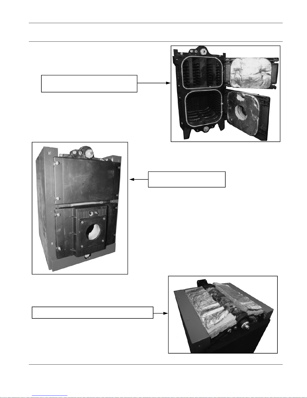
Completed boiler block with burner door and
flue pass door hinged on the right.
Front view showing the side jackets
and the doors bolted closed.
Top view showing insulation prior to fitting the top jacket.
STREBEL CIS
ASSEMBLY INSTRUCTIONS FOR: STREBEL CIS
Page 13
V.1-03.08
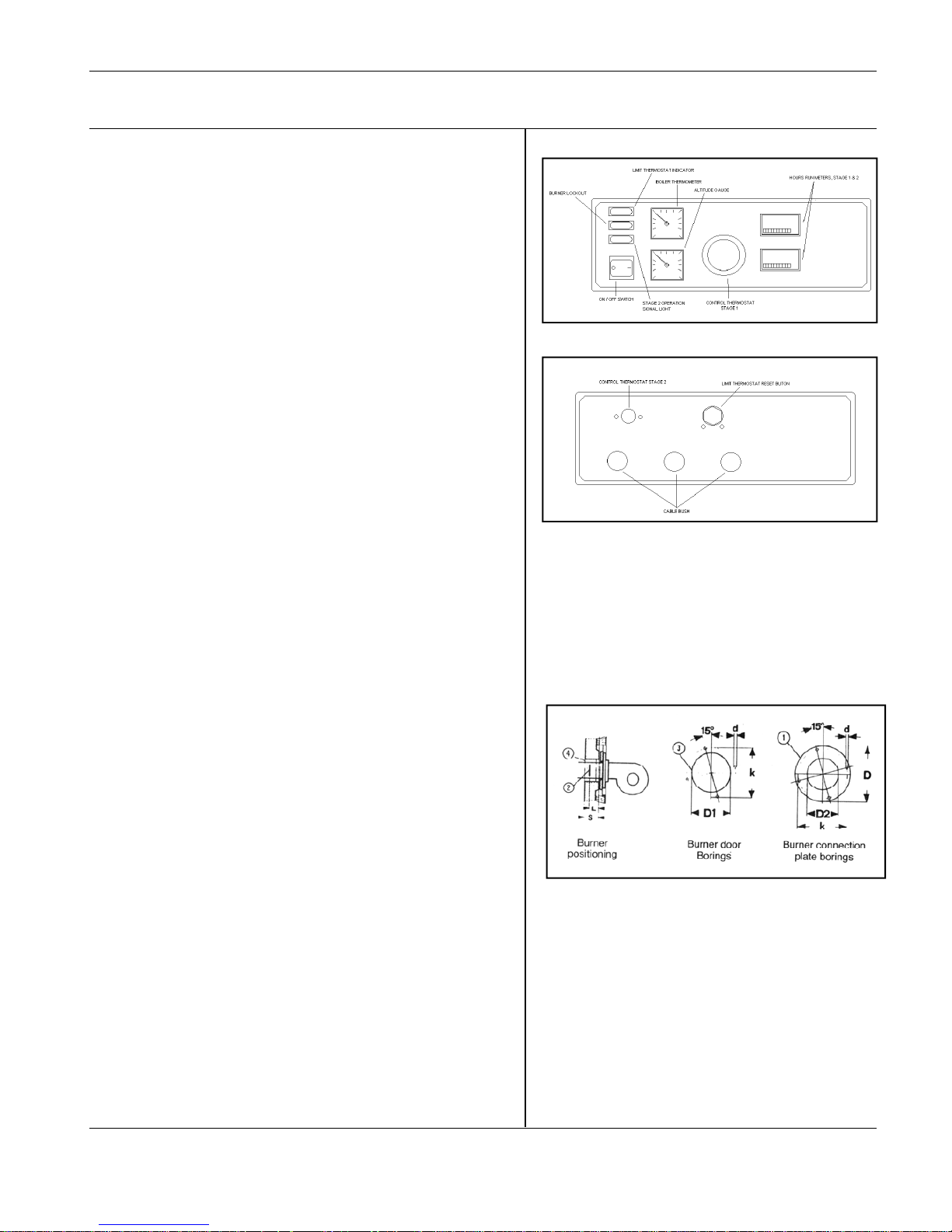
Instrument control panel assembly.
Description of the instrument control panel
Instrument control panel OS-04 consists of the following parts:
→ Instrument panel casing.
→ Altitude (pressure) sensor.
→ Thermometer.
→ Stage 1 control thermostat.
→ Stage 2 control thermostat.
→ Limit thermostat.
→ Hours run counter for stage 1 & 2.
→ Stage 1 and stage 2 ON/ OFF lamps.
→ Burner lockout lamp (reset button).
→ Terminal connections.
Assembly of instrument control panel
1. Attach instrument control panel casing to the upper jacket on the
boiler.
2. Push the altitude (pressure) sensor, thermometer, stage 1&2
thermostats and the limit thermostat, wiring through the slotted hole
in the upper jacket.
3. Push connection wires through into the control panel and connect
according to the wiring diagram.
4. The burner connections run from the burner to the conduits on the
side jackets and again up through the slotted hole in the upper jacket
to the control panel.
5. Ensure unused holes in the control panel casing are plugged with
rubber stoppers.
WARNING: The length of the wires should be such that there is enough
wire to fully open and close the burner door.
Assembling the burner
1. Only have the burner commissioned by a qualified combustion
engineer. Cables and pipes for electricity and oil should be fitted
flexible to allow full swing of door.
2. Fit burner to burner door with a suitable burner plate
3. When assembling the burner, the position of the diffuser disc (2)
should be observed.
4. The largest possible diameter of the burner is limited by the boring
(3) in the burner door
5. With regard to the choice of burner, the burner head equipment
stipulated by the manufacturer concerned should be used
6. Wrap burner draught tube with cerafelt fibre to insulate gap (4)
7. Electrical connection should be made according to the circuit
diagram in the instrument panel and IEE regulations. Please follow
operating instructions for details regarding burner setting.
The burner should only be commissioned by a Qualified Combustion
Engineer

STREBEL CIS
ASSEMBLY INSTRUCTIONS FOR: STREBEL CIS
Page 14
V.1-03.08
W
I
R
I
N
G
D
I
A
G
R
A
M
LEGEND: 1.1 ON /OFF SWITCH.
1.2 TERMINAL BLOCK.
1.3 SOLENOID SAFETY VALVE.
1.4 HIGH LIMIT THERMOSTAT.
1.5 BOILER CONTROL THERMOSTAT STAGE 1.
1.6 HIGH TEMPERATURE LIMIT INDICATION LAMP.
1.7 BOILER CONTROL THERMOSTAT, STAGE 2.
1.8 BURNER CONNECTORS.
1.9 ROOM THERMOSTAT*.
* IF ROOM THERMOSTAT IS NOT FITTED, LINK TERMINALS 9 & 10. T1 CONTROL CIRCUIT FEED.
T2 CONTROL CIRCUIT RETURN TO BOILER .
S3 BURNER LOCK-OUT LAMP.
S4 STAGE 2 INDICATOR LAMP.
B4 HOURS RUN METER, STAGE 1.
B5 HOURS RUN METER, STAGE 2.
T6 HIGH/LOW CONTROL CIRCUIT FEED.
T7 HIGH/LOW CHANGEOVER CONTROL CIRCUIT .
T8 HIGH/LOW CONTROL CIRCUIT RETURN.

STREBEL CIS
ASSEMBLY INSTRUCTIONS FOR: STREBEL CIS
Page 15
V.1-03.08
T
E
R
M
I
N
A
L
D
I
A
G
R
A
M
LEGEND: 1.1 ON /OFF SWITCH.
1.2 TERMINAL BLOCK.
1.3 SOLENOID SAFETY VALVE.
1.4 HIGH LIMIT THERMOSTAT.
1.5 BOILER CONTROL THERMOSTAT STAGE 1.
1.6 HIGH TEMPERATURE LIMIT INDICATION LAMP.
1.7 BOILER CONTROL THERMOSTAT, STAGE 2.
1.8 BURNER CONNECTORS.
1.9 ROOM THERMOSTAT*. * IF ROOM THERMOSTAT IS NOT FITTED, LINK TERMINALS 9
& 10. T1 CONTROL CIRCUIT FEED.
T2 CONTROL CIRCUIT RETURN TO BOILER .
S3 BURNER LOCK-OUT LAMP.
S4 STAGE 2 INDICATOR LAMP.
B4 HOURS RUN METER, STAGE 1.
B5 HOURS RUN METER, STAGE 2.
T6 HIGH/LOW CONTROL CIRCUIT FEED.
T7 HIGH/LOW CHANGEOVER CONTROL CIRCUIT .
T8 HIGH/LOW CONTROL CIRCUIT RETURN.

STREBEL CIS
ASSEMBLY INSTRUCTIONS FOR: STREBEL CIS
Page 16
V.1-03.08
Before start-up check whether:
1. There is sufficient water in the boiler and the heating system;
the pointer on the altitude (pressure) gauge is in the green
sector.
2. All valves in the heating flow and return are open.
3. The heating system has been fully vented.
4. The burner door is closed securely.
5. The burner plug is wired in correctly.
6. The fresh air supply to the boiler room is open.
7. Oil or gas supply is sound and purged.
8. All fuses are intact.
9. The mains switch is turned on.
Fault finding
Heating is cold
• Is boiler up to temperature? Check correct heat settings of
heating circuit controls.
• If automatic control does not operate ie is faulty, switch off
“control” switch off “control” switch and regulate via “manual”
control. Consult specialist.
• If boiler temperature has dropped and burner indicates
malfunction, refer to the burner suppliers’ instructions (press
malfunction button).
General check on whether:
• Fuse is intact.
• Mains switch is turned on and other controls are calling for
heat.
• Burner plug is correctly plugged in.
• Heating pump and filling pump are operating.
• Burner indicates malfunction.
• Control is switched on and displays the correct time.
• All valves are open.
• Fuel is available.
• All switches and knobs are set as per instructions.
• Boiler has switched off due to excess temperature.
Maintenance
• Clean the boiler regularly, proceed as follows:
− Turn off mains switch and control.
− Open burner door.
− Clean heating gas flue-ways and combustion chamber.
− Close burner door and tighten nuts firmly.
• Never tap water from the boiler for domestic use.
• If the system is to be out of operation for an extended period
of time, clean the boiler thoroughly , spray it out with a
mixture of oil and graphite and close the door firmly.
• If there is a frost hazard when the system is out of operation,
drain the boiler. Leave the stop-cock open (unless it contains
anti-freeze).
• Perform maintenance of heating controls and burner
according to the manufacturers’ instructions.
Hazards:
• Operate the boiler at a maximum temperature of 95ºC. If the
boiler overheats as a result of incorrect operation, switch the
burner off immediately. Do not refill with water until the boiler
has cooled off.
• Never fill the hot boiler with cold water.
• Flue gas temperature of less than 160ºC can cause sooting in
masonary chimneys.
• Consult the heating installers’ service department if heating
gas flue-ways become severely fouled or condensation
occurs.
• Only refill the oil tank when the system is switched off. Start up
no earlier than the next day, so the dirt which has been
disturbed in the tank can settle again.
• Inspect the door seal gasket between the front section and the
door. If the gasket is damaged, a specialist should fit a
replacement. Close the cleaning door ensuring it is firmly
sealed. Check all the door bolts are firmly tightened.

STREBEL CIS
ASSEMBLY INSTRUCTIONS FOR: STREBEL CIS
Page 17
V.1-03.08
STREBEL LTD
1F ALBANY PARK INDUSTRIAL ESTATE
FRIMLEY ROAD, CAMBERLY
SURREY GU16 7PL
TELEPHONE : (01276 685422) FAX: (01276 685405)
E-mail address: info@strebel.co.uk
Website: www.strebel.co.uk
THE COMPANY RESERVES THE RIGHT TO CHANGE SPECIFICATIONS AND DIMENSIONS WITHOUT NOTICE
E. & O.E.
 Loading...