

Strebel Ca 7s, BCa7s, Ca 7s-4, Ca 7s-5, Ca 7s-6 Installation And Operating Instructions Manual
...
Page 1
23/03/01
Ca 7s and BCa 7s
61-235 kW
INSTALLATION AND
OPERATING
INSTRUCTIONS

Page 2
23/03/01
CONTENTS:
Dimensions for Ca7s and BCa7s boilers.
General specification
Boiler room clearance requirements
Boiler block assembly
Pulling up the sections
Boiler block assembly & connections
Ca7s Jacket assembly
Calorifier assembly
BCa7s Jacket assembly
Continued
Electrical connection and Instrument control panel
Continued
Control module options
Control module diagrams
Installation of electronic control modules
Terminal wiring diagram
Schematic wiring diagram
Important notes & burner connection information.
PAGE:
3 & 4
5
6
7
8
9
10
11
12
13
14
15
16
17
18
19
20
21
Page 3
23/03/01
General Specifications
The STREBEL Camino 7s is a special boiler for oil or
gas fired pressure jet burner.
In the BICALOR construction a calorifier for the
supply of hot water is built onto the boiler.
CSH-S type calorifiers are manufactured from 1.4571
high tensile steel with an incorporated heating coil of
galvanised copper ribbed pipe.
Triple pass block of cast iron sections.
The first pass is the combustion chamber. From there
the flue gases pass between the rear section and the last
intermediate section through the second pass to the
front of the boiler. They are then diverted into the third
pass and flow back to the rear through the flue spigot
into the chimney.
Flue baffles of cast iron can be introduced into the flue
passes in order to influence the flue gas temperature
depending on chimney conditions.
The boiler can be used with an oil or gas burner.
Brief description.
• Corrosion resistant block of cast iron sections.
• Triple pass boiler with optimised use of energy.
• High efficiency.
• Built-in instrument panel with multiple control
possibilities and retro-fit control options.
• Easy erection and cleaning.
• Modern design.
Operating conditions
Boiler:
Maximum operating temperature up to 110ºC
Maximum operating temperature up to 120ºC
depending on technical safety of the equipment.
Maximum operating pressure 4.0 bar
Maximum test pressure 5.2 bar
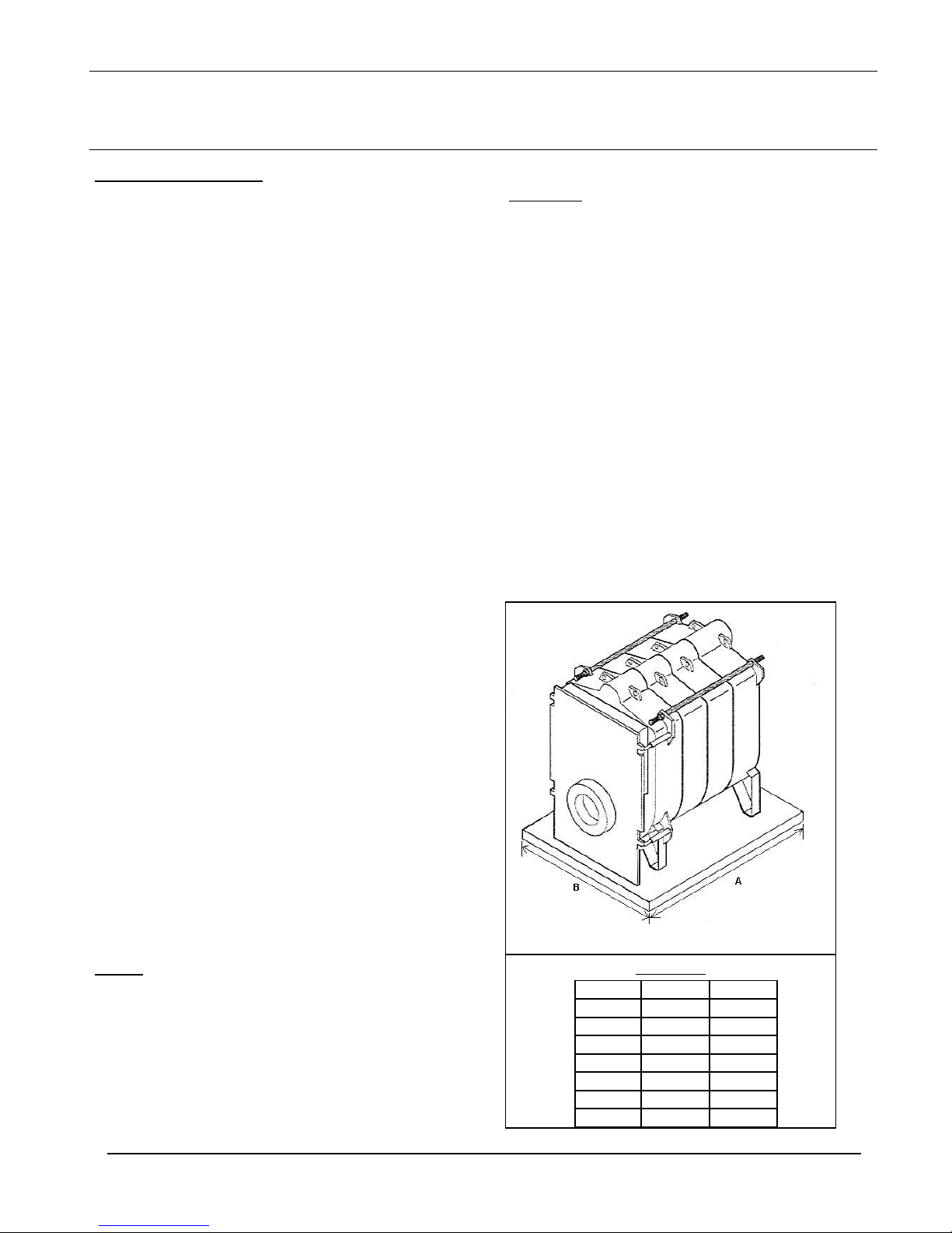
Min thickness = 60mm
A B
Ca 7s-4 965 810
Ca 7s-5 1115 810
Ca 7s-6 1265 810
Ca 7s-7 1415 810
Ca 7s-8 1565 810
Ca 7s-9 1715 810
Ca 7s-10 1865 810
Dimensions
ASSEMBLY INSTRUCTIONS FOR: Ca 7s / BCa 7s
Calorifier:
Maximum operating pressure 10 bar
Maximum test pressure 13 bar
The boiler can be delived in individual sections
or as a boiler block. The accessories are packed
seperately. There are different orders of
assembly depending on the condition of supply.
when assembling and connecting the boiler, all
relevant instructions should be observed.
The boiler is to be erected on a base, or a level
floor which is capable of supporting the weight
of the boiler, water content and any ancillary
equipment. Refer to base details opposite.
Assembly, connections and the initial set-up
operation should be carried out by a qualified
heating engineer.
Page 4
23/03/01
ASSEMBLY INSTRUCTIONS FOR: Ca 7s / BCa 7s
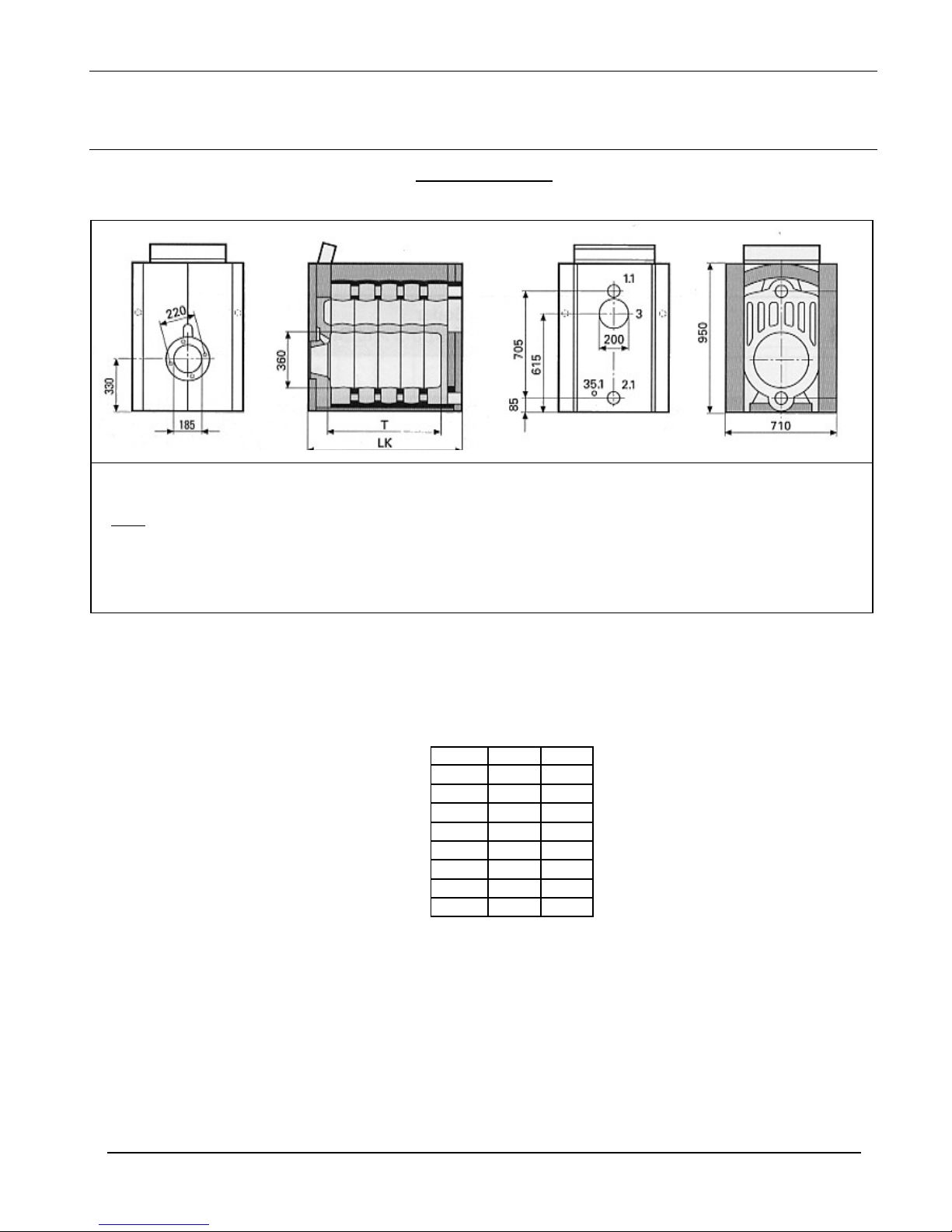
Boiler Dimensions
Ca 7s - Dimensions
Boiler LK mm Tmm
Ca7s-4 865 555
Ca7s-5 1015 705
Ca7s-6 1165 855
Ca7s-7 1315 1005
Ca7s-8 1465 1155
Ca7s-9 1615 1305
Ca7s-10 1765 1455
KEY:
1.1 Boiler Flow 130mm NW65
2.1 Boiler Return 130mm NW65
35.1 Boiler Drain 3/4”
Page 5
23/03/01
ASSEMBLY INSTRUCTIONS FOR: Ca 7s / BCa 7s
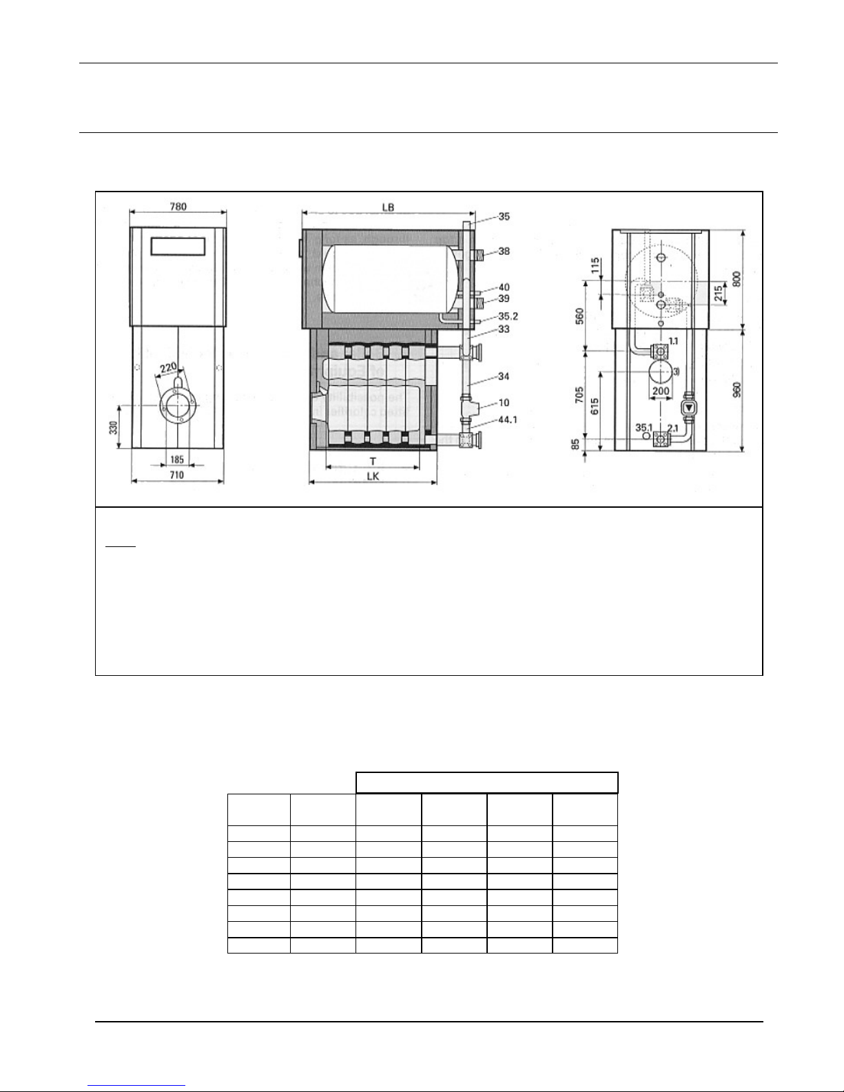
BCa 7s - Dimensions
LK Calorifier Type CSH-
Boiler
240S 300S 360S 500S
LK mm mm mm mm mm
Ca7s-4 865 1175
Ca7s-5 1015 1175 1475
Ca7s-6 1165
1475 1625
Ca7s-7 1315
1475 1625 2075
Ca7s-8 1465
1625 2075
Ca7s-9 1615
2075
Ca7s-10 1765
2075
1.1 Boiler flow 130mm NW65
2.1 Boiler return 130mm NW65
10 Primary pump 1x230V 1¼”
33 Primary connection pipe (1¼”*) 1½”
34 Return connection pipe (1¼”*) 1½”
35 Air vent 3/8 “
35.1 Boiler drain off ¾”
35.2 HWS drain off ¾”
38 HWS water connection flow (1½”*) 2”
39 Cold water connection (1½”*) 2”
40 Circulation connection ¾”
44.1 Non return valve
* Available for calorifier CSH 240S
KEY:

Page 6
23/03/01
Diagram showing clearances required in boiler room.
The clearance details shown above are required for access to the boilers for maintenance purposes. Slight
variations may apply, depending on the specific installation.
ASSEMBLY INSTRUCTIONS FOR: Ca 7s / BCa 7s
Page 7
23/03/01
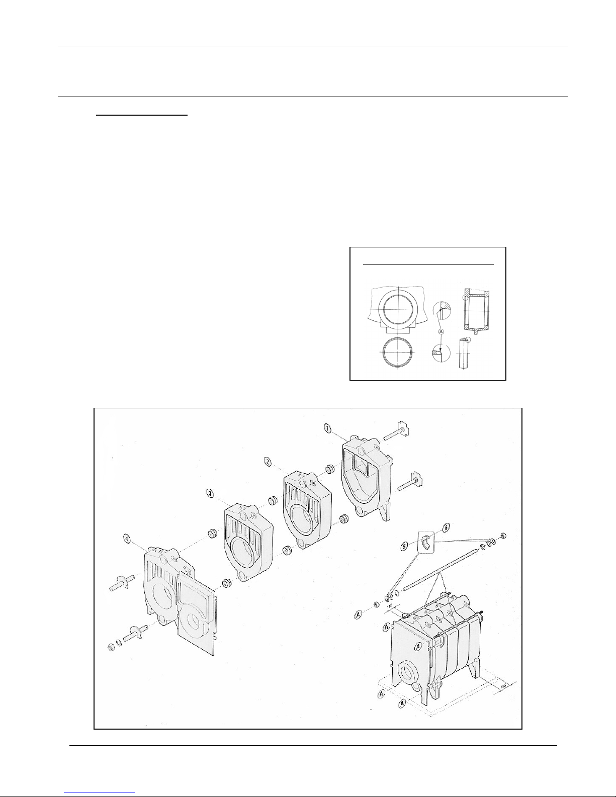
Once assembled, the boiler block is to be secured with
the tie bars (2 at the top, and 2 at the bottom). Prior to
screwing nuts up ensure the two disc springs (5)&(6)
are slotted on with concave sides facing each other.
The nuts can now be tightened until the disc springs
flatten.
The burner door hinges should now be fitted on the
left or right hand side of the front section depending
on requirements. Ensure the eyelet screws (door
hinge) are at the same depth and when the door is
closed it should press flat with the front section.
Boiler Block Assembly
The boiler block is assembled by ‘pulling-up’ each
section in turn starting from the rear section (1). All
other sections (2)(3)(4) are mounted individually
using the pulling-up tools.
One face of the adjoining sections must have a length
of mastic sealing strand placed into the mastic groove.
Each of the boiler nipples must be inspected to ensure
there is no damage apparent. The nipples and nipple
ports should then be kept free from dirt and checked
at each stage of assembly. Particles of dirt which are
not removed lead to leakage.
The accompanying nipple jointing oil serves as a
lubricant as well as a waterproof seal and must be
used.
Boiler nipples and nipple ports must align exactly at
all stages of assembly. An inclined, retracted nipple
leads to leakage.
The clearance between the sections throughout the
pulling-up stages should always be even. If the
clearance is uneven, a flat chisel should be inserted
into the narrower point and the sections pulled up
until the clearance is even again.
Diagram showing nipple & boring
ASSEMBLY INSTRUCTIONS FOR: Ca 7s / BCa 7s
 Loading...