


Biotec
Installation and user manual
Product information

Biotec
Typographical and printing errors, changes
in construction and dimensions expected.
2
Risk of electric shock
Works with parts marked with this symbol are only
to be carried out by an electrician. Text passages
with this symbol hold information about electric connections.
Caution
Working on parts marked with this symbol can cause
injury or material damage. Text passages with this
symbol hold information about safety precautions.
Possible hand injuries
Working on parts marked with this symbol can cause
hand injuries.
Fire hazard
Flammable items may not be positioned near the boi ler. Text passages with this symbol hold information
about fi re prevention.
Danger of frost
Frost forming in the system pipes after a longer
period of downtime during the cold season can cause
severe damages. Text passages with this symbol hold information
about frost prevention.
Additional notices
Follow regional prescriptions on positioning, installation, operation and disposal of the boiler.
Every person with the intend of operating the boiler is prescribed
to carefully read this manual. This applies especially for the safety informations. Even persons intending to clean the boiler or
perform other maintenance must read this manual. Otherwise, the
guaranty expires.
This manual is to be stored safely.
Safety information
Basics
The boiler must be installed by a competent professional. The Biotec is produced according to current safety requirements. Incorrect
use can cause accidents, injury or even death of the user, if the
rules for safe use are ignored. This can also cause damages to the
boiler or to other items next to the boiler. The specialist responsible for the implementation must explain the proper handling of
the boiler to the user. Only use the boiler if it is installed properly.
Always follow the instructions of this manual. Every boiler failure
must be fi xed as soon as possible.
Use of the boiler
The manufacturer is not responsible for damages resulting from
an inappropriate use. In this case, the user is responsible.
The operation parameters can only be modifi ed in the range
prescribed in this manual. The use of parameters outside the range can cause damages or errors in the system.
Prescribed fuel
This boiler is designed for the combustion of wood pellets. The
use of other fuels is prohibited. Wood pellets are cylindrical and
made from wood scraps without additives or chemical binders. The
pellets must have specifi cal dimensions and a low moisture level.
STREBEL recommends pellets with a diameter of 6 to 8 mm and a
lenght of 10 to 30 mm. Quality and form are prescribed throughste standards ÖNORM 7135 and DIN 51731. Only use pellets that
comply with ÖNORM, DIN or equal regional stadards. More informations in chapter 3.
Possible risks
Carbon monoxyde
During boiler operation, carbon monoxyde can issue
through the boiler doors. Only leave them open as
long as necessary. Insuffi cient vent during operation is critical.
Closing the vent of the boiler room or the boiler is prohibited.
Signs and symbols
Surfaces with high temperatures
Touching such surfaces can cause burns. Surfaces
marked with this symbol may only be touched when
the system is cooled down. Text passages with this symbol hold
information about hot boiler parts.
Safety information
Caution
injury or material damage. Text passages with this
Working on parts marked with this symbol can cause
hand injuries.
Flammable items may not be positioned near the boi-
ler. Text passages with this symbol hold information
Frost forming in the system pipes after a longer
period of downtime during the cold season can cause
through the boiler doors. Only leave them open as

Biotec
Typographical and printing errors, changes
in construction and dimensions expected.
3
Contents
1 Boiler features ................................................................................................................................ 4
2 Technical data ................................................................................................................................ 5
3 Fuel ................................................................................................................................................. 7
4 Construction and funtion ................................................................................................................ 8
5 Installation...................................................................................................................................... 9
6 Boiler controller .............................................................................................................................. 18
7 Phases of operation........................................................................................................................ 22
8 Maintenance .................................................................................................................................. 23
9 Possible malfunctions .................................................................................................................... 24
10 First start-up ................................................................................................................................... 25
11 Disposal of the boiler ..................................................................................................................... 26
Terminal connections ..................................................................................................................... 27

Biotec
Typographical and printing errors, changes
in construction and dimensions expected.
4
1 Boiler features
1.1 General information
The boiler Biotec has a modern design and is made of high quality
material. The boiler testings were carried out conform to EN 3035, so the boiler fulfi lls all requirements for the connection to the
central heating system. The maximum permitted system pressure
is 2.5 bar.
This boiler is suitable as central heating system for single- or multi-family-homes, small businesses or workshops. The automatic
operation shows to be very user-friedly, because the only action
during operation is re-fi lling the pellet silo every day to every couple of days, depending on the current output. The Biotec includes
the silo and pellet screw. The basic design of the boiler features
the silo on its right side. On request and for additional charge,
the silo can be mounted on the left side resp. a bigger silo can be
installed.
Pellets make an excellent fuel. Wood pellets are zylindrical and
made from wood sraps. The ash-percentage after the combustion
is especially low with pellets and accounts for about 1 %. The
caloric value of pellets is approx. 18000 kJ/kg, wich means that 2
kg pellets comply to 1 l light heating oil.
The storing qualities and the high energy value of pellets make
them the ideal replacement for oil or gas. Additionally, they are
produced from wood, a regional renewable source.
Boiler features
1.2 Conformity declaration
The company STREBEL confi rms according to EN45014:1998 that
the boiler Biotec complies with the following standards:
EC-guidelines:
MD 98/37/EC
PED 97/23/EC
LVD 2006/95/EC
EMC 2004/108/EC
Harmonized standards:
EN 303-5:1999; EN 60204-1:2006; EN 60335-1:2002;
EN 50165:1997+A1; EN 61000-6-3:2001; EN ISO 12100-1:2003;
EN ISO 12100-2:2003; EN 1050:1997
Other standards and technical spezifi cations:
EN 287-1:2004, EN 288-3:1992; EN 10204:2004; EN ISO
7000:2004.
Used method for testing conformity: Modul B1
Grenzwert der Emission der Verbrennungsprodukte (Klasse) 3
Certifi cates: EC Control Type –Certifi kate Nr. 0745/350/09
Responsible laboratory: TÜV Thüringen e.V. Service-Center
Südthüringen, Industriestr.13, D-98544 Zella-Mehlis
We hereby declare that the mentioned products were produced
under safety- and norm prescriptions, guidelines and standards.
All working conditions and terms of use comply with this manual.
In case the product is changed in a way we are not informed of,
this confi rmation loses its validity.

Typographical and printing errors, changes
in construction and dimensions expected.
5
Biotec
Technical data
2 Technical data
Pelletskessel Biotec 25 Biotec 25 S Biotec 40
Rated output kW 25 25 40
Minimum output kW 8 8 13
Flow-/Return temperature °C 90/70 90/70 90/70
Flue gas temperature at rated output °C 135 - 140
Minimum fl ue gas temperature °C 95 95 95
Flue gas volume fl ow at rated output kg/s 0,0176 - 0,0280
Flue gas volume fl ow at min. output kg/s 0,0079 - 0,0140
Effi ciency % 88 91 85
Water volume l 70 74 118
Resistance on water side
t=10 K/t=20 K
hPa 7/2 7/2 7/2
Weight kg 320 340 459
Boiler class N 303-5 3 3 3
Maximum operating/testing pressure bar 2,5/5 2,5/5 2,5/5
Maximum fl ue draft Pa 12 - 15
Connection fl ow/return inch 1 1 5/4
Exhaust connection diameter mm Ø 130 130 130
Pellet silo volume l 200 500 400
Maximum volume of silo
(extra charge)
l 400 - -
Electric connection 230 V ~ 50 Hz (max. 1 A) 230 V ~ 50 Hz (max. 1 A) 230 V ~ 50 Hz (max. 1 A)
Power consumption
ignition/fan/screw motor
W 400/41/50 400/41/50 400/41/50

Biotec
Typographical and printing errors, changes
in construction and dimensions expected.
6
Technical data
2.1 Dimensions
Boiler diameters (mm)
Overall width (W) Depth (D) Height (H)
Diameter
exhaust
conn. (DE)
Boiler width
(W2)
Height
return (R)
Height
fl ow (F)
Centre
exhaust
conn. (HE)
Biotec 25
1275 (200 L silo) 905 1435 130 500 269 1132 1130
Biotec 25 S
1443 (500 L silo) 905 1630 130 500 269 1132 1330
Biotec 40
1645 (400 l silo) 1070 1660 130 708 254 1301 1330
Connections (inch)
R1 R2 R3
Biotec 25
1 1/2 3/4
Biotec 25 S
1 1/2 3/4
Biotec 40
5/4 1/2 3/4
D
W
W2
R
F
H
HE
Pellet silo dimensions (mm)
Silo volume W. H. D.
Lid half-
height
Lid max
height
200 Litre
765 1350 650 - 1990
400 Litre
for Biotec 25
935 1350 750 1715 2100
400 Litre
for Biotec 40
935 1625 750 1990 2375
500 Litre
935 1545 750 1910 2295
DE

Biotec
Typographical and printing errors, changes
in construction and dimensions expected.
7
Fuel
3 Fuel
3.1 Required fuel-quality
DIN 51731
Pellet-size HP5, made from by-products of wood and woodshavings, without additives. The energy value of 2 kg pellets complies with the energy of 1 l light heating oil (10 kWh).
ÖNORM 7135
The Austrian standard comprises quality requirements of pellets,
testing regulations, supervision of pellet production and labelling.
DIN Plus
Standard DIN Plus combines Standard DIN 51731 and Standard
ÖNORM 7135. The certifi cation procedure at the manufacturer‘s
works is carried out by the responsible certifi ed DIN-inspector. The
quality of the pellets is supervised and checked regularly.
Standard DIN 51731 ÖNORM 7135 DIN Plus
Length mm max. 50 max. 5 x diameter max. 5 x diameter
Diameter mm 4-10 max. 10 max. 10
Chaloric value MJ/kg 17.5 - 19.5 min. 18 min. 18
Pellet density kg/m
3
1 - 1.4 min. 1.12 min. 1.12
Pellet bulk density kg/m
3
min. 650 min. 650 n.a.
Water content % max. 12 max. 10 max. 10
Ash content % max. 1.5 max. 1.5 max. 0.5
Abraison of the pellets % n.a. max. 2.3 max. 2.3
Sulphur content % n.a. max. 0.04 max. 0.04
Nitrogen content % n.a. max. 0.3 max. 0.3
Chlorine content % n.a. max. 0.2 max. 0.2
Biotec
Typographical and printing errors, changes
in construction and dimensions expected.
8
Construction and function
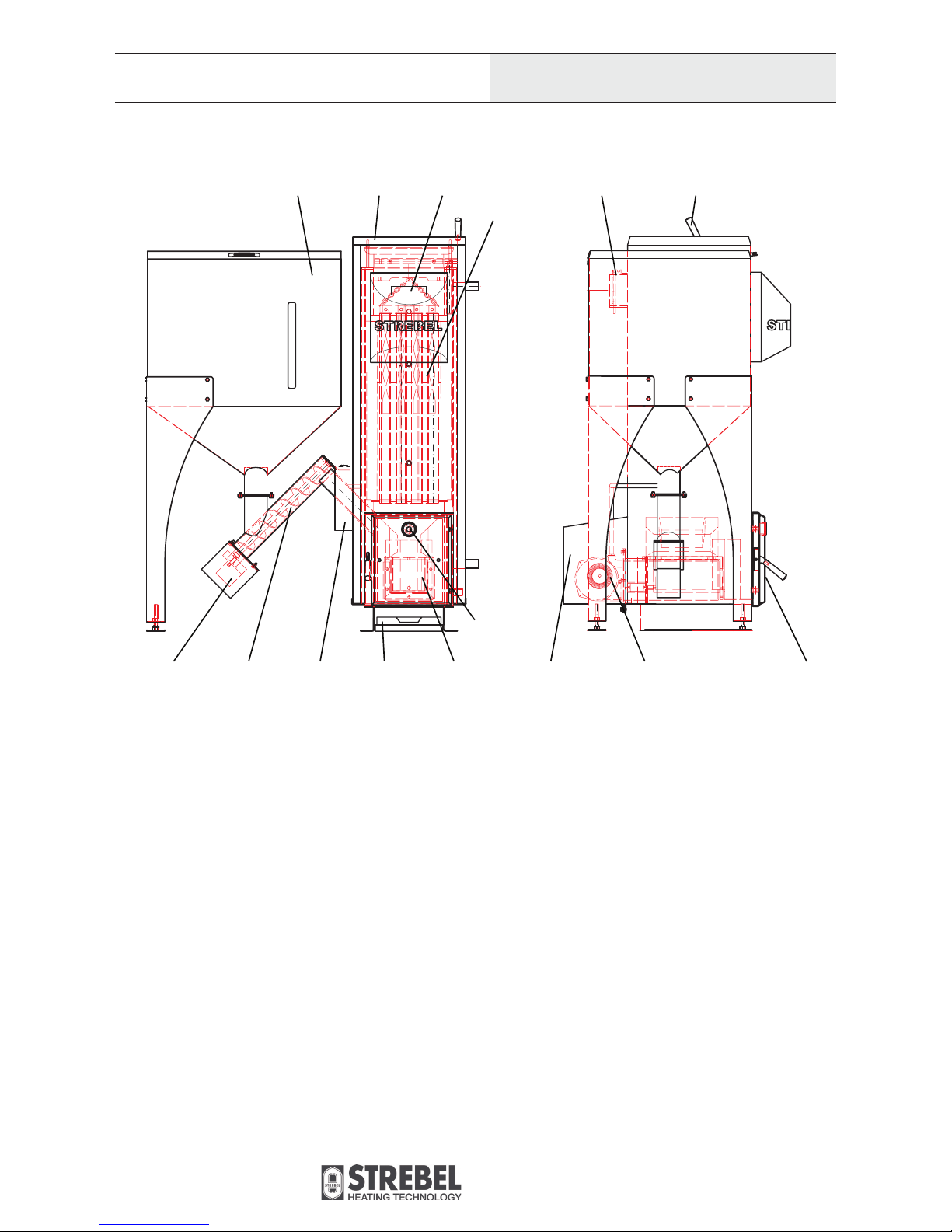
4. Construction and function
4.1 Construction
Construction of the boiler
Legend:
1 Burner
2 Heat exchanger w. turbulators
3 Pellet silo
4 Pellet screw
5 Gear motor
6 Case of heat exchanger
7 Case of burner
8 Fan
9 Combustion chamber door
10 Exhaust connection and exhaust probe
11 Cleaning lever
12 Controller panel
13 Ash drawer
14 Application box
15 Sight glas
4.2 Function
The application box (14) houses the main switch for turning the
boiler on and off. Boiler operation can be adjusted via pushbuttons on the controller panel (12). If the combustion process is
started, the gear motor (5) of the pellet screw (4) starts to run.
It conveys pellets from the silo (3) to the burner (1). Combustion
takes place in the combustion chamber and can be inspected via
the sight glass (15). The fan (8) provides primary and secundary
air for combustion. The pellet ash falls into the ash drawer (13)
through the openings of the combustion chamber fl oor. The turbulator-spirals within the heat exchanger tubes (2) can be moved up
and down with the cleaning lever (11) to remove cloggings from
the inside of the tubes.
Caution! The combustion chamber door (9) must be closed during
boiler operation. The ash drawer and the combustion chamber may
only be touched and cleaned when the boiler has cooled down.
1
15
1314 9874
5
2
3 106 12 11

Biotec
Typographical and printing errors, changes
in construction and dimensions expected.
9
A
B
AB
Hydraulische
Weiche
Rücklaufanhebung
Regumat RTA 130 DN 25
Netz 230 V / 50 Hz
Pelletskessel Biotec 25
Speicher
RTH
SF
SLP
HKP
RTH Raumthermostat
SF
Speicherfühler
SLP Speicherladepumpe
HKP Heizkreispumpe
AG Ausdehnungsgefäss
WW Warmwasser
KW Kaltwasser
Sicherheitsgruppe
Kaltwasser
Brauchwassermischer
Warmwasser
KW
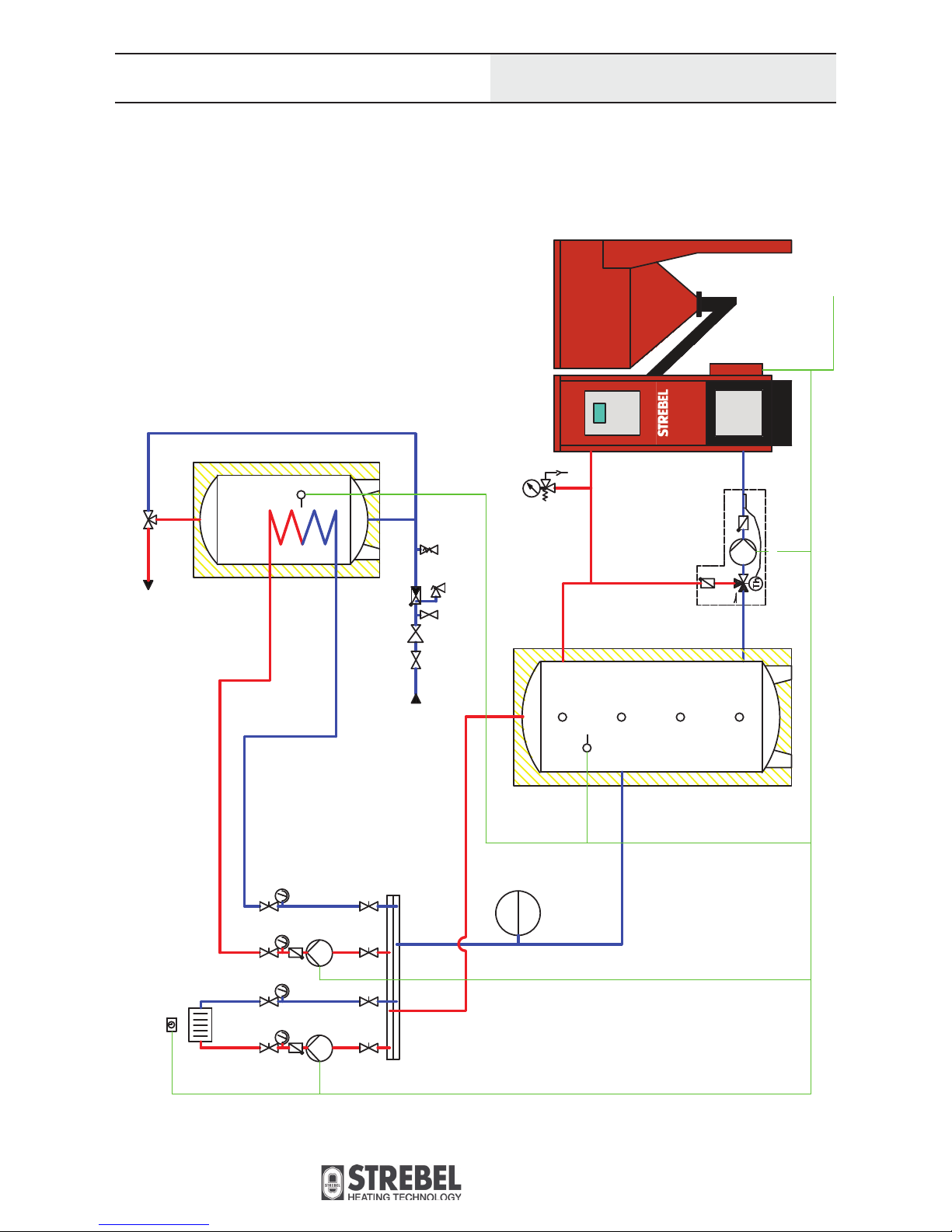
Connection scheme with domestic water tank
Installation
5 Installation
The installation of the boiler and other system components must be
carried out by qualifi ed technicians.
5.1 Hydraulic scheme examples
Room thermostat
Domestic water probe
Tank charging pump
Heating circuit pump
Expansion vessel
Hot water
Cold water
Pellet boiler Biotec 25
Power supply 230 V/50 Hz
Return riser
Hydraulic
compensator
Safety group
cold water
Tank
Domestic water mixer
Hot water
TCP
HCP
RTH
DWP
TCP
HCPEVHW
CW
CW
DWP
HW
EV
Biotec
Typographical and printing errors, changes
in construction and dimensions expected.
10
Installation
Connection scheme with domestic water tank and compensator tank
A
B
AB
Rücklaufanhebung
Regumat RTA 130 DN 25
Netz 230 V / 50 Hz
Pelletskessel Biotec 25
RTH
SLP
HKP
RTH
Raumthermostat
SF
Speicherfühler
PF Pufferfühler
SLP Speicherladepumpe
HKP
Heizkreispumpe
AG Ausdehnungsgefäss
WW Warmwasser
KW
Kaltwasser
Pufferspeicher
PF
Speicher
SF
Sicherheitsgruppe
Kaltwasser
Brauchwassermischer
Warmwasser
KW
Room thermostat
Domestic water probe
Compensator tank probe
Tank charging pump
Heating circuit pump
Expansion vessel
Hot water
Cold water
RTH
DWPCPTCP
HCPEVHW
CW
Pellet boiler Biotec 25
Power supply 230 V/50 Hz
Return riser
Compensator tank
TCP
HCP
EV
Safety group
cold water
Tank
Domestic water mixer
Hot water
CW
HW
DWP
CP

Biotec
Typographical and printing errors, changes
in construction and dimensions expected.
11
Installation
A
B
AB
Rücklaufanhebung
Regumat RTA 130 DN 25
Netz 230 V / 50 Hz
Pelletskessel Biotec 25
RTH
RTH Raumthermostat
AG
Ausdehnungsgefäss
Connection scheme with room thermostat
Return riser
EV
Room thermostat
Expansion vessel
RTH
EV
Pellet boiler Biotec 25
Power supply 230 V/50 Hz

Biotec
Typographical and printing errors, changes
in construction and dimensions expected.
12
Installation
A
B
AB
Rücklaufanhebung
Regumat RTA 130 DN 25
Netz 230 V / 50 Hz
Pelletskessel Biotec 25
Ceta 106 Regelgerät
Ceta RC
Raumgerät
VF Vorlauffühler
AF
Aussenfühler
PF
Pufferfühler
MIMO
Mischermotor
MKP
Mischerkreispumpe
AG
Ausdehnungsgefäss
WW Warmwasser
KW
Kaltwasser
Speicher im Speicher System
PF
Ceta 106
Ceta 106
VF VF
Ceta RC Ceta RC
AF
MKP
MIMO
MKP
MIMO
Sicherheitsgruppe
Kaltwasser
Brauchwassermischer
Warmwasser
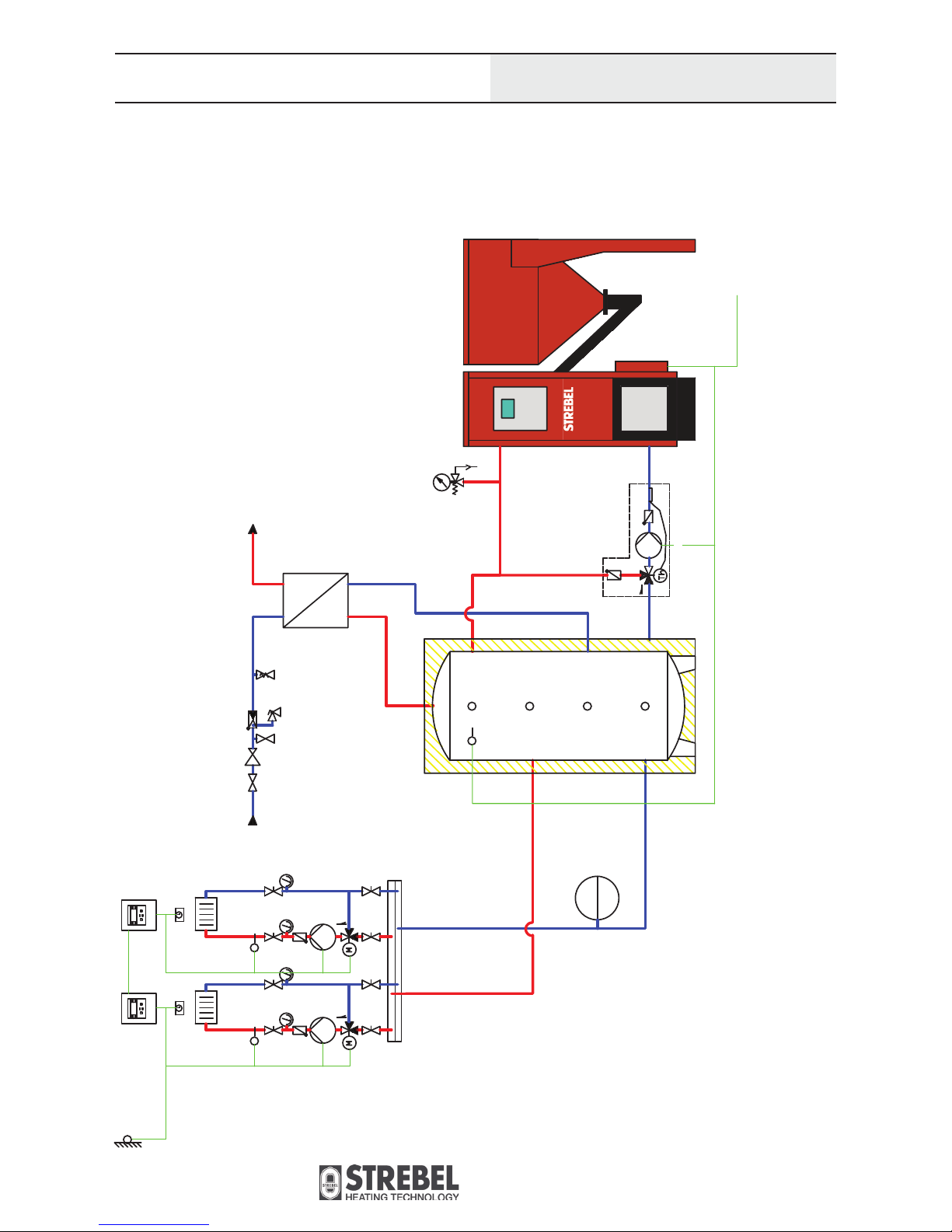
Connection scheme with tank-in-tank system and 2 heating circuits
Pellet boiler Biotec 25
Power supply 230 V/50 Hz
Controller
Room remote controller
Flow probe
Outside probe
Compensator tank probe
Mixer motor
Mixer circuit pump
Expansion vessel
Hot water
Cold water
Ceta 106
Ceta RCFPOPCPMMO
MCPEVHW
CW
Return riser
HW
FP
FP
MCP MCP
EV
OP
Safety group
cold water
Tank-intank system
Domestic water mixer
Hot water
CW
CP
Biotec
Typographical and printing errors, changes
in construction and dimensions expected.
13
Installation
A
B
AB
Rücklaufanhebung
Regumat RTA 130 DN 25
Netz 230 V / 50 Hz
Pelletskessel Biotec 25
Ceta 106
Regelgerät
Ceta RC Raumgerät
VF
Vorlauffühler
AF
Aussenfühler
PF
Pufferfühler
MIMO Mischermotor
MKP
Mischerkreispumpe
AG
Ausdehnungsgefäss
FRIWA Frischwassermodul
WW
Warmwasser
KW
Kaltwasser
Ceta 106
Ceta 106
VF
VF
Ceta RC
Ceta RC
AF
MKP
MIMO
MKP
MIMO
KW
WW
FRIWA
PF
Sicherheitsgruppe
Kaltwasser
Connection scheme withcompensator tank, 2 heating circuits and freshwater-module
Cobtroller
Room remote controller
Flow probe
Outside probe
Compensator tank probe
Mixer motor
Mixer circuit pump
Expansion vessel
Fresh water module
Hot water
Cold water
Ceta 106
Ceta RCFPOPCPMMO
MCPEVFREWAHWCW
FREWA
CW
HW
CP
Safety group
cold water
Pellet boiler Biotec 25
Power supply 230 V/50 Hz
Return riser
FPFP
MCP MCP
EV

Biotec
Typographical and printing errors, changes
in construction and dimensions expected.
14
A
B
AB
Rücklaufanhebung
Regumat RTA 130 DN 25
Netz 230 V / 50 Hz
Pelletskessel Biotec 25
Ceta 106 Regelgerät
Ceta RC
Raumgerät
VF Vorlauffühler
AF
Aussenfühler
PF Pufferfühler
MIMO
Mischermotor
MKP Mischerkreispumpe
AG Ausdehnungsgefäss
WW Warmwasser
KW Kaltwasser
Ceta 106
Ceta 106
VF VF
Ceta RC
Ceta RC
AF
MKP
MIMO
MKP
MIMO
PF
Kombipufferspeicher
Brauchwassermischer
Warmwasser
Brauchwasser-
Ausdehnungsgefäss
Sicherheitsgruppe
Kaltwasser
Installation
Connection scheme with combined compensator tank and 2 heating circuits
Controller
Room remote controller
Flow probe
Outside probe
Compensator tank probe
Mixer motor
Mixer circuit pump
Expansion vessel
Hot water
Cold water
Ceta 106
Ceta RCFPOPCPMMO
MCPEVHW
CW
HW
HW
CP
CW
EV
EV
Safety group
cold water
Combined compensator tank
Domestic water mixer
Hot water
Domestic water
expansion vessel
Pellet boiler Biotec 25
Power supply 230 V/50 Hz
Return riser
FP
FP
MCP MCP
OP

Biotec
Typographical and printing errors, changes
in construction and dimensions expected.
15
Installation
A
B
AB
Rücklaufanhebung
Regumat RTA 130 DN 25
Netz 230 V / 50 Hz
Pelletskessel Biotec 25
SLP
Pufferspeicher
PF
Speicher
SF
Sicherheitsgruppe
Kaltwasser
Brauchwassermischer
Warmwasser
KW
Ceta 106
VF
Ceta RC
AF
MKP
MIMO
Ceta 106
Regelgerät
Ceta RC Raumgerät
VF
Vorlauffühler
AF Aussenfühler
SF
Speicherfühler
PF Pufferfühler
MIMO
Mischermotor
MKP
Mischerkreispumpe
AG
Ausdehnungsgefäss
WW
Warmwasser
KW
Kaltwasser
Connection scheme with combined compensator tank, 1 heating curcuit and DW-circuit
Pellet boiler Biotec 25
Power supply 230 V/50 Hz
Return riser
FP
FP
MCP MCP
EV
CW
CP
DW-tank
OP
HW
DP
Domestic water mixer
Hot water
Controller
Room remote controller
Flow probe
Outside probe
Domestic water tank probe
Compensator tank probe
Mixer motor
Mixer circuit pump
Expansion vessel
Hot water
Cold water
Ceta 106
Ceta RCFPOPDPCP
MMO
MCPEVHW
CW
Safety group
cold water
Compensator tank
Biotec
Typographical and printing errors, changes
in construction and dimensions expected.
16
5.2 Installation place and chimney
The boiler must be installed near a chimney. It is prohibited to
close air vents.
WARNING!
1.) The boiler must be placed on a solid and stable fl oor.
2.) The installation must be carried out by qualifi ed technicians.
3.) The boiler room must be equipped with water- and grounded
electrical connection. A waste water draw-off is advantage ous.
4.) The boiler room must be vented in a suffi cient way.
5.) Floor, walls, ceiling, door and equipment of the room must be
made of non-fl ammable material.
Installation
Additional notes:
1.) Humidity should be kept at a low level to avoid corrosion of
metal parts.
2.) For the fi lling of the boiler we advise to use soft water.
3.) The circulation pump must not operate before the heating
system is completely fi lled with water. The system must be
bled.
4.) When connecting the boiler to the fl ue it is necessary to put
the fl ue pipe inhorizontally or vertically. All connections
must be sealed up properly.
5.) Before the fi rst start-up, check the position of the chamotte
bricks to make sure they fi t correctly and were not shifted
during transportation of the boiler.
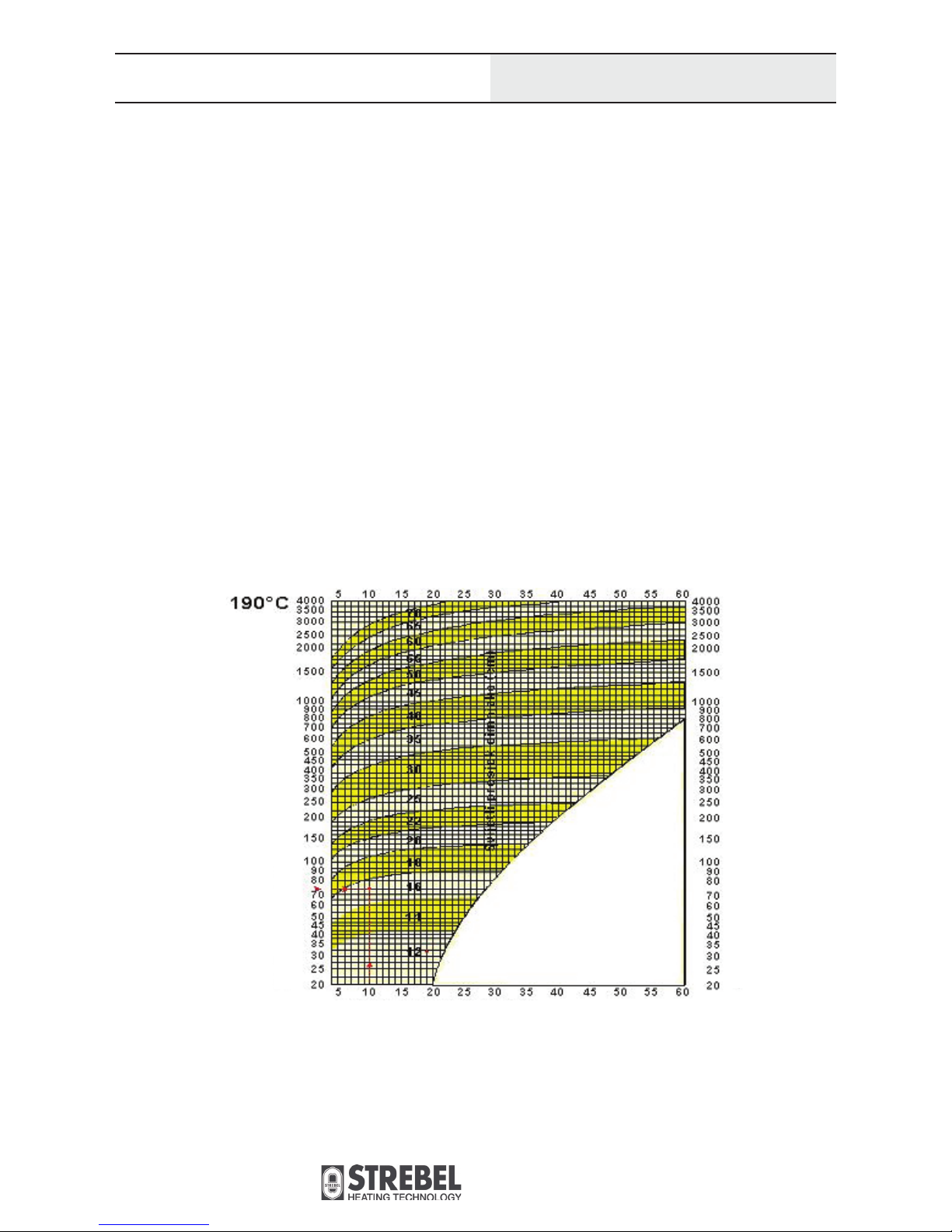
6.) The chimney must be layed out according to diagram below.
An insuffi cient fl ue draft holds a fi re risk. In that case, the fi re
can spread from the burner on to the screw and the pellets in the
silo.
Rated output [kW]
Chimney height [m]
Rated output [kW]

Biotec
Typographical and printing errors, changes
in construction and dimensions expected.
17
Installation
Examples of correct chimney installation
5.3 Connection of the boiler parts
Connect the electric wire of the pump to the power supply. (max.
current 1 A).
Connection of the controller
Connect the electric wire of the controller to the power supply.
The installation of the electric accessories of the boiler needs a
power supply with 230 V/50 Hz.
Connection of the room thermostat
A room thermostat can be connected to the controller. Before starting up the boiler, check the following:
1.) Water pressure in boiler and system.
2.) System must be bled.
3.) The wires of the boiler are installed correctly, undamaged
and not touching surfaces that heat up during operation.
4.) The chamotte-bricks are correctly positioned in the burner.
5.) The pellet silo is properly clean.
A certifi ed safety valve (2.5 bar) and an expansion vessel must
be installed in the heating system. Do not install other valves
between the safety valve and the vessel. The return temperature
must not fall below 60 °C to prevent the build of condensate inside the boiler.
Installation scheme of the thermo-chamotte-bricks
inside the burner.
To prevent system freeze or if the boiler will not be
used for a longer period of time, we advise to fi ll the
system with a an antifreeze or to drain the system.
To prevent system freeze or if the boiler will not be
used for a longer period of time, we advise to fi ll the
system with a an antifreeze or to drain the system.
5.3 Connection of the boiler parts

Biotec
Typographical and printing errors, changes
in construction and dimensions expected.
18
6.2 Basic display
In the line „Boiler operation phase“ (13), information about the
current phase of boiler operation (Boiler OFF, First ignition-phase,
Combustion-phase, Cool-down phase, Room thermostat OFF, etc.)
The symbol „Boiler operation“ shows if the boiler is active or not.
If the boiler is set to run in a pre-programmed operation mode, the
display shows „TIME“.
The symbols in the bottom line show the operational availability
of the controller outputs resp. if the elemets (fan, pump, screw,
ingniter, boiler pump) are active or not. If the symbol shows, that
component is active.
Boiler controller
6 Boiler controller
6.1 Control panel
The controller is used for regulating the pellet boiler operation.
The design of the control panel is shown in the scheme below:
The controller has an LCD display and 6 buttons on the right side
of the display.
Functions of the buttons
Increase of parameter values
Escape, boiler power off
Browse menu – go back
Browse menu – go forward
Decrease of parameter values
Enter, confi rm selected parameter
Inputs
- Boiler probe (Pt 1000)
- Flue gas probe (Pt 1000)
- Domestic water probe (NTC, 10 kΩ)
- Compensator tank probe (NTC, 10 kΩ)
- Room thermostat
- Input – GSM controller
Outputs
- Ignition electrode (relay, 8A, NO)
- Pellet screw (relay, 5A, NO)
- Fan (PWM)
Legend
1 Time
2 Boiler operation
3 DW-tank temperature
4 Fan activated
5 Pump
6 Pellet screw
7 Ignition electrode
8 Boiler pump
9 Preset power output
10 Flue gas temperature
11 Current boiler temperature (desired)
12 Program
13 Boiler operation phase
1
2
3
4
5 6 7 8
10
9
11
12
13
Biotec
Typographical and printing errors, changes
in construction and dimensions expected.
19
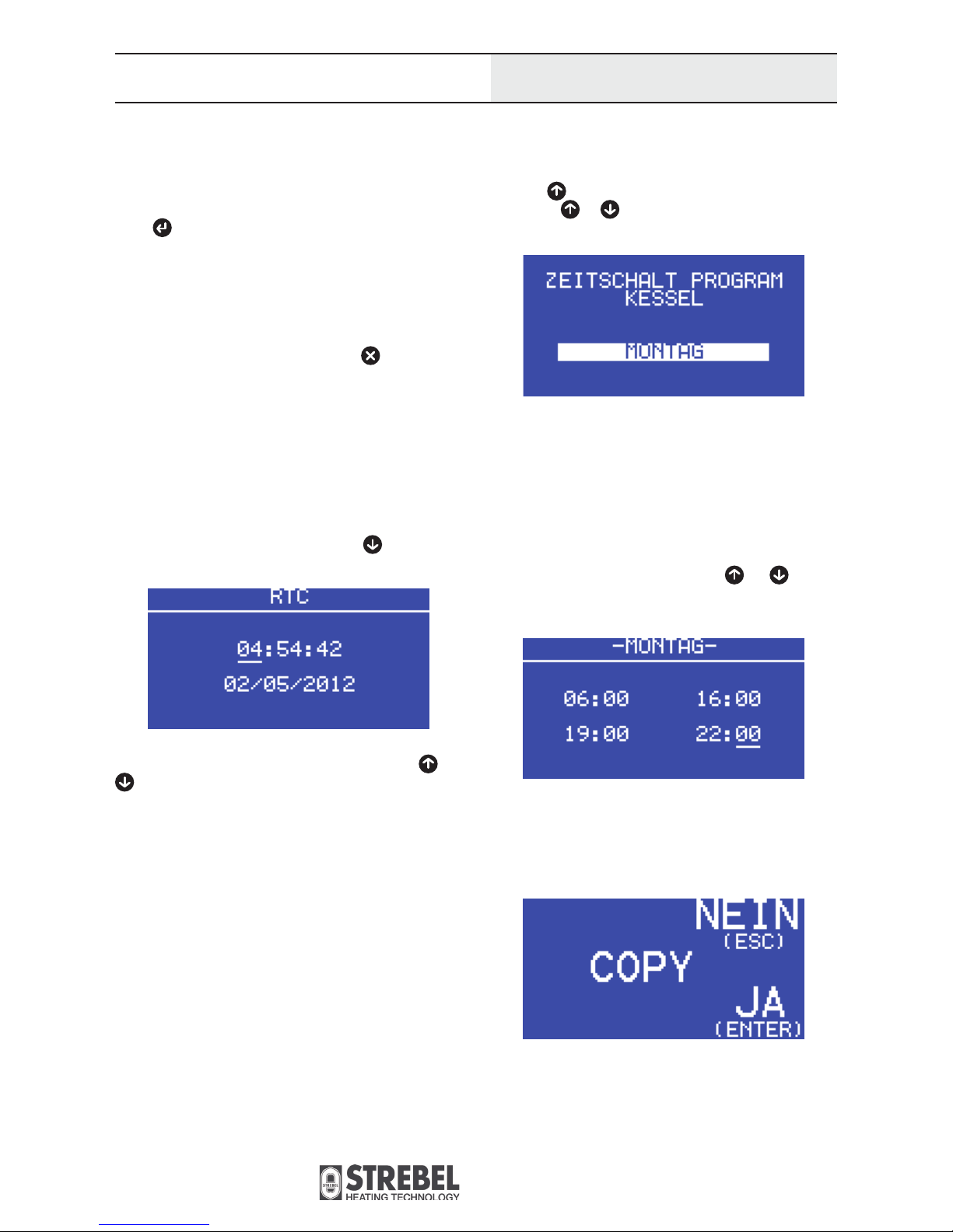
6.5 Automatic operation
To set the hours of operation for the automatic operation, press
the button for about 2 seconds. The weekday can be selected
by pressing or . To change the operating hours for the
selected day, press the enter button.
The display shows two rows of each two time-sets, the fi rst is the
start of operation, the second is the time for operation stop. In the
example below, the boiler starts up at 06:00 am and deactivated
at 04:00 pm. After a pause, operations starts again at 07:00 pm
and stops at 10:00 pm. Then the boiler is deactivated until the next
day. The operation times can be set individually for every day of
the week.
The values can be changed with the buttons and and confi rmed with the enter button. After confi rming, the selection shifts
ahead one position.
After all four sets are confi rmed, the display shows „COPY“. If this
is confi rmed with the enter button, the settings are copied to the
next day. Pressing the escape button leads to the settings for the
next weekday, without copying the changes.
Boiler controller
6.3 Start and stop of the boiler
To start the boiler, activate the red main switch on the right side
of the boiler. After activation, the boiler controller turns on and
shows the basic display. To start boiler operation, press the enter
button for about 2 seconds. The display shows „ON“ and the
boiler switches into the pre-pulse phase with maximum fan power.
To switch to automatic operation, the enter button is again pressed
for about 2 seconds. Then, the display shows „TIMER PROGRAM
BOILER“.
To shut down the boiler, the escape button is pressed for
about 2 seconds until the display shows „OFF“. The boiler switches to the cool-down phase with decreased fan power. To deactivate the boiler, the escape button is again pressed for about 2
seconds. By deactivating the main switch, the boiler is powered
down completely.
6.4 Setting of time and date
For the setting of date and time the button
is pressed for
about 2 seconds.
The current selection can be changed with the buttons and
. With the enter button, the selection is confi rmed and shifts
ahead one position. The seconds can not be set. When all positions are set, the user reaches the basic display. To escape the
setting without making changes, press the escape button.
Biotec
Typographical and printing errors, changes
in construction and dimensions expected.
20
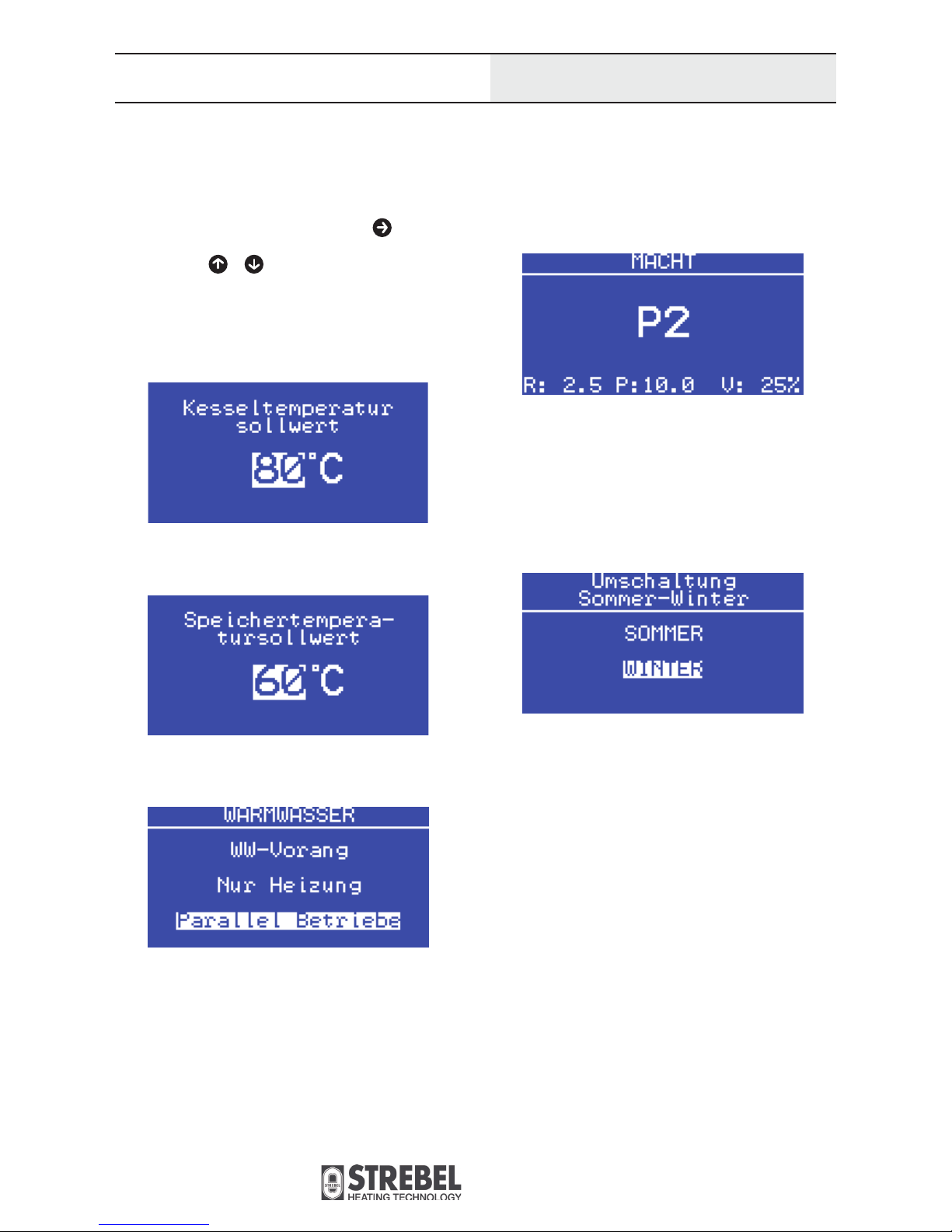
4.) POWER:
The large position in the middle shows the set power stage. The
row below shows the set values of the Operating duration of
screw (R), the Pausing duration of screw (P) and the - Fan-power
during heating operation (V).
P1: Minimum output operation
P2: Intermediate output operation
P3: Maximum output operation
5.) Switching between summer- and winter-mode
In summer-mode, the boiler only produces heat for domestic
water.
6.6 Operation parameters
The following parameters are relevant for boiler operation, pellet
combustion, and fl ue gas temperature. The parameters are set by
the technician before the fi rst start-up (see 6.7). The operation parameters are displayed by pressing the button in the basic
display.
Press the buttons or to set the value for the selected parameter. Press the escape button to go back to the basic display.
Press the enter button to confi rm the selection.
1.) Boiler temperature rated value:
2.) Tank temperature rated value:
3.) DOMESTIC WATER:
Boiler controller

Biotec
Typographical and printing errors, changes
in construction and dimensions expected.
21
Boiler controller
6.7 Setting parameters
Changes of particular parameters can be done by pressing
the buttons
and at the same time. Below, a list of the
parameters with the factory settings in brackets (value Biotec 25/
value Biotec 40).
The parameters can be altered by pressing
or . The setting
is confi rmed with the enter button and the menu directs the user
back to the basic display.
S1: Duration of start-up fan (30 s/30s)
S2: Fan-power (100 %/100 %)
S3: Duration of screw start-up dose (30 s/30 s)
S4: Fan-power during start-up (30 %/30 %)
S5: Delayed start of ignition (60 s/60 s)
S6: Duration of start-up ignition (60 s/60 s)
S7: Fan-power during ignition (80 %/80 %)
S8: Duration of second ignition (600 s/600 s)
S9: Duration of stabilisation (200 s/200 s)
S10: Operating duration of screw during stabilisation (1,5 s/1,5 s)
S11: Pausing duration of screw during stabilisation (10,0 s/10,0 s)
S12: Fan-power during stabilisation (90 %/90 %)
S13: Stabilisation delay (300 s/300 s)
S14: Operating duration of screw P1 (2,5 s/4,0 s)
S15: Pausing duration of screw P1 (10,0 s/10,0 s)
S16: Fan-power during heating operation P1 (40 %/55 %)
S17: Operating duration of screw P2 (3,0 s/4,5 s)
S18: Pausing duration of screw P2 (10,0 s/10,0 s)
S19: Fan-power during heating operation P2 (45 %/60 %)
S20: Operating duration of screw P3 (3,0 s/5,0 s)
S21: Pausing duration of screw P3 (10,0 s/10,0 s)
S22: Fan-power during heating operation P3 (46 %/62 %)
S23: Duration of cool-down phase (240 s/240 s)
S24: Power of fan during cool-down phase (50 %/50 %)
S25: Boiler delay with room thermostat OFF (0 s/0 s)
S26: Max. fl ue gas temp. for ignition (100 °C/100 °C)
S27: Min. fl ue gas temp. (7,0 °C/7,0 °C)
S28: Min. Abgastemperatur (50 °C/50 °C)
S29: Max. decrease of fl ue gas temp. (20 °C/min / 20 °C/min)
S30: Duration of disregarded fl ue gas temp. in partial load opera tion (30 min./30 min)
S31: Minimum operation (5 °C/5 °C)
S32: Factor of boiler rated value for modulation (10 x/10 x)
S33: Fan-power reduction permitted (5 %/5 %)
S34: Hysteresis (5,0 °C/5,0 °C)
S35: Turn-on temp. for return increase pump (55 °C/55 °C)
S36: Diff. between turn-on and -off temp. (10 °C/10 °C)
S37: Pump overrun with RT OFF (0 s/0 s)
S38: Difference boiler to tank (5,0 °C/5,0 °C)
S39: Boiler probe adjustment (0,0 °C/0,0 °C)
S40: Flue gas probe adjustment (0,0 °C/0,0 °C)
S41: Compensator tank probe adjustment (0,0 °C/0,0 °C)
S42: Domestic water probe adjustment (0,0 °C/0,0 °C)

Biotec
Typographical and printing errors, changes
in construction and dimensions expected.
22
The pump is activated if the boiler temperature rises beyond the
required temperature and if the room thermostat is activated.
If the room thermostat is not activated, the pump runs for a period
of time (5 minutes) after deactivation. After that period, the pump
stops until the room thermostat is activated again.
7 Operation phases
7.1 Ignition phase
If the fl ue gas temperature rises beyond the limit for triggering ignition, the controller registers that the burner room holds enough
ember to successfully continue combustion. In this case, the ignition electrode is deactivted. The dosage of pellets continues.
If the fl ue gas temperature falls below the limit for triggering ignition, the boiler switches to ignition phase. In this phase the fan
is activated to clean the burner room, especially the vents below
the ignition electrode. After that, the pellet screw starts working.
It despenses the starting amount of pellets for ignition. When the
duration of screw start-up dose is over, the ignition electrode is
activated. After a successful igntion, the fl ue gas temperature rises and the boiler switches to warm-up phase.
7.2 Warm-up phase
The ignition electrode is deactivated and the dosage of pellets
reduced. The fan is running with increased speed in comparison to
combustion phase (according to the setting). The warm-up phase
has the purpose to fan the fi re and let it spread across the pellets
in the burner. The duration of the warm-up phase is temporary.
After this phase, the combustion phase starts.
In the case that the fl ue gas temperature does not rise beyond
the set point, the controller registeres that the pellets can not be
ignited and the boiler stops operation. The display shows „Failed
ignition“.
7.3 Combustion phase
During combustion phase, the pellet and air supply are regulated
based on the parameter settings. The controller aims for the boiler
to increase the temperature up to the „Maximum boiler temperature“. After that is done, the boiler slowly reduces its output to
prevent repeated turing off and on of the burner. The boiler shifts
to pause mode when the temperature reaches the „Maximum boiler temperature“. On the top row the display shows „Rated temp.
reached“.
The boiler continues operation when the temperature of the fl ow
water drops below the parameter „Maximum boiler temperature“.
The current fl ue gas temperature determines if the boiler operation starts with the warm-up phase or ignition.
If a room thermostat is used, it is possible to activate the setting
that turns off the boiler resp. sends it into a phase of afterrun if
the room thermostat is turned off. If the afterrun-function is used,
the boiler will quickly reach the required temperature and stops
operation.
Operation phases

Biotec
Typographical and printing errors, changes
in construction and dimensions expected.
23
When cleaning the burner room with a vacuum clea ner, the ash inside must be cooled down to prevent
accidents.
When removing the front brick of the burner, there
is a risk of burn when handling it shortly after
deactivation of the boiler because it may still be hot.
Allow the boiler to cool down an adequate period of time until the
bricks can be touched safely.
There is a risk of burns when cleaning the exhaust passes because
these surfaces can reach a temperature of up to 200 °C during
operation. Wait until these parts cool down before cleaning.
8 Maintenance
8.1. Intervals of maintenance and cleaning
The maintenance work performed periodically is very important
for a problem-free operation und guarantee a long life of the boiler
and other system components.
The maintenance periods relate to the pellet quality and boiler
output. Soot and tar cling to the burner room walls, so the burner
room must be cleaned periodically by hand.
Before you start the cleaning, turn off the boiler controller and
deactivate the main switch.
Maintenance
Interval Components Application
Every 3 days
Clean heat exchanger and
burner room
Move the lever of the heat exchanger cleaning system back and forth 5 to
6 times. Remove the front chamotte brick and clean the burner room with
a vacuum cleaner.
Every month Clean pellet silo Empty out the pellet silo and remove the wood dust with a vacuum cleaner.
Every 6 months
Clean display Carefully clean with slightly damp cloth.
Check and clean exhaust
passes
The exhaust pipes can be removed and cleaned with the cleaning tool
when the system is cooled down.
Check and clean boiler
and fl ue gas probe
Pull out the probes, remove soot and lime.
Once a year
Clean all parts mentioned
above
When cleaning the burner room with a vacuum clea-
ner, the ash inside must be cooled down to prevent
accidents.
When removing the front brick of the burner, there
is a risk of burn when handling it shortly after
deactivation of the boiler because it may still be hot.
While cleaning, mind that there is a choking hazard
due to carbon monoxyde passing out if the boiler is
in operation. In this case, carbon monoxyde extits the
opened boiler doors. Do not leave the boiler doors open longer
than necessary.
The ash mass in the burner room depends on the pellet quality.
High quality pellets case less ash in the burner room and less
wood dust in the pellet silo.
To prolong the livetime of the ignition electrode which ignites teh
pellets, the electrode itself and the air vent must be cleaned regularly.
Thoroughly clean the system at the end of the heating season to
prolong its livetime and raise its effi ciency.
While cleaning, mind that there is a choking hazard
due to carbon monoxyde passing out if the boiler is
in operation. In this case, carbon monoxyde extits the

Biotec
Typographical and printing errors, changes
in construction and dimensions expected.
24
9 Possible malfunctions
Possible malfunctions
Malfunction/error Possible cause Solution
The boiler is working but does not reach
the set temperature.
1.) Boiler is polluted.
2.) Not enough fuel in burner.
3.) The chamotte bricks in the burner room
are not placed correctly.
1.) Clean the boiler.
2.) Set the screw to longer running time.
3.) Place the bricks correctly.
The boiler is wet.
Flue gas condensation.
The radiator power is too high or the
boiler output is to low. Meaning: replace
the boiler with an other that has a higher
output or adjust the number of radiators to
the boiler output.
Defects in the boiler.
Weld leaking parts on the boiler. This
is carried out by customer service or an
installler.
The fl ue gas is escaping insuffi ciently.
Flue gas pipes or heat exchangers are dirty. Clean the parts.
The chimney opening is too small.
Adjust chimney diameter to the boiler
output.
The boiler does not start operation. No power supply or blackout.
1.) Check electric connections.
2.) Check fuse in domestic electrical
installation.
The boiler reaches set temperature but the
radiators stay cold.
The circuit pump is not working (this pump
is not delivered with the boiler).
De-block the circuit pump by opening the
cover and turn shaft with a screw driver.
No potential on the circuit pump. Check fuse of circuit pump.
The fan does not work.
1.) Blown fuse.
2.) Foreign substance in the fan.
1.) Replace fuse.
2.) Check if fan can be turned without
resistance.
Failed pellet ignition.
1.) No power supply or blackout.
2.) Ignition electrode error.
3.) Burner is dirty.
4.) Pellet silo is empty.
5.) Ignition not callibrated correctly.
6.) Fan error.
7.) Screw error.
8.) Flue gas probe error.
1.) Check fuse.
2.) Replace ignition electrode.
3.) Clean burner room.
4.) Refi ll pellet silo.
5.) Callibrate ignition.
6.) Fix malfunction of fan.
7.) Fix malfunction of gear motor or screw.
8.) Replace probe.
Blocked screw.
1.) No power supply or blackout.
2.) Foreign substance in the screw.
3.) Pellets are damp.
4.) Gear motor of the screw is defective.
1.) Check fuse.
2.) Clean pellet silo and screw channel.
3.) Use dry pellets or pellets of higher
quality.
4.) Replace gear motor.

Biotec
Typographical and printing errors, changes
in construction and dimensions expected.
25
9.1 Fire prevention of the silo
In the case that the boiler is not connected to a suitable fl ue gas
system (not enough height, wrong diameter of the chimney, decreased diameter because of dirt or heavily polluted boiler), there is a
possibility that fi re spreads from the burner into the silo.
A part of the combustion air supply is led through the screw channel and thus prevents backfi re in the pellet silo. This air current is
present at all times during operation.
If the fl ue gas system is badly designed or heavily polluted, the
air supply may not be enough to stop a backfi re. In this case, the
thermal valve is activated which releases tempering water if a
temperature of 95 °C or more is measured. The fi re is extinguished
that way. The thermal valve and the probe are mounted on the
boiler ex factory.
The buyer is obligated to provide a water supply to the thermal
valve (1/2“ connection) and to comply with the prescriptions regarding dimension and quality of the fl ue gas system. If the fl ue
gas system is designed incorrectly or heavily polluted or if the boiler is not cleaned regularly, the manufactorer is not liable for fi re
caused by such failures.
9.2 Measures after thermal valve release
1.) Disconnect boiler from power supply.
2.) Remove screw and gear motor.
3.) Clean out damp pellets from the silo and the screw channel.
4.) Mount screw and gear motor.
5.) Remove residual water and dry damp system parts. Moisture
can cause electrical shorts.
6.) Connect to power supply.
If the damp pellets are not removed completely, screw and motor
may jam. The manufactorer rejects responsibility and the guaranty
expires if material damage occurs because of such failures.
Possible malfunctions,
First start-up
9.1 Fire prevention of the silo
Scheme of thermal valve
10 First start-up
The fi rst start-up of the boiler Biotec may only be carried out by a
professional of the company STREBEL or an experienced installer.
If the start-up is not carried out correctly, the boiler and the system
can be damaged or destroyed or injury and material damage can
occur.
10.1 Precautions for the fi sr start-up
1.) Disconnect boiler from power supply.
2.) Check if the red main switch on the boiler side is activated.
3.) Check if the following parts are installed professionally and
working.
- All mechanical parts of the boiler,
- burner and chamotte bricks,
- fan,
- circuit pump,
- safety valve.
4.) Check of all electrical connections:
- Correct installation of all electric components (gear motor,
fan, controller, display),
- Protection of unused connections,
- ground,
- power supply.
10 First start-up
Thermal valve
Probe

Biotec
Typographical and printing errors, changes
in construction and dimensions expected.
26
11 Disposal of the boiler
11.1 Removal
The boiler removal must be carried out by qualifi ed technicians.
Otherwise, injury or material damage can occur.
Procedure of the removal
1.) Stop boiler operation.
2.) Wait until the pellets in the burner room are burnt up and the
boiler is cooled down.
3.) Disconnect the boiler from power supply.
4.) Disconnect the boiler from the rest of the heating installation
with a turncock and drain the water from the boiler.
5.) Remove pellet silo.
6.) Remove boiler shell.
7.) Remove mineral wool insulation from the boiler body.
11.2 Disposal
The steel parts of the boiler are delivered to a recycling centre:
- Boiler body,
- boiler shell,
- pellet silo,
- screw,
- gear motor,
- burner.
The electrical parts as well as glas parts, mineral wool and plastic
parts are seperately delivered to the recycling centre.
The boiler parts must not be disposed in the domestic waste bin.
Disposal of the boiler,
Guaranty
11 Disposal of the boiler

Biotec
Typographical and printing errors, changes
in construction and dimensions expected.
27
Terminal connections
COMPENSATOR TANK
PROBE NTC10K
DOMESTIC WATER
TANK NTC10K
ROOM THERMOSTAT
SCREW
230 VAC, 50 Hz, 50 W
FAN
230 VAC, 50 Hz, 41 W
IGNITION
230 VAC, 400 W
RETURN RISER
230 VAC, < 500 W
TANK CHARGER PUMP
230 VAC, < 500 W
CIRCUIT PUMP
230 VAC, <500 W
POWER SUPPLY
230 VAC, 50 Hz
3 x 1,5 mm
2

A - 2700 Wiener Neustadt, Wiener Strasse 118
Teleph. +43 (0)2622 235 55-0
Fax +43 (0)2622 253 46
verkauf@strebel.at
www.strebel.at
Strebelwerk GmbH
STREBEL customer service:
Teleph. +43 (0)2622 23555 70-72,93,94
Fax +43 (0)2622 84344
kundendienst@strebel.at
 Loading...