

Strebel ATI SP 80, ATI SP 120, ATI SP 220, ATI SP 300, ATI SP 400 Installation, Operation And Maintenance Manual
ATI SP 80 ATI SP 120
STREBEL ATI SP
DIRECT FIRED STORAGE WATER HEATER
ATI SP 220 ATI SP 400 ATI SP 300
INSTALLATION, OPERATING
AND MAINTENANCE MANUAL
Sept - 01

2
ATI SP 80, 120, 220, 300, 400 – INSTALLATION INSTRUCTIONS
Sept
-
01
• The following instruction book is integral and essential part of the appliance, and it has to be
kept with care near the appliance, for any further consultation.
• The appliance has been manufactured for hot water production: any other use of it has to be
considered dangerous and not suitable.
• The appliance is not to be installed in damp rooms, it has to be protected from water splashes
or other liquids, to avoid anomalies to electrical and thermal devices.
• Installation has to be made by professional qualified people, who are responsible and aware of
the safety regulations in force. A wrong installation, caused by not observing the manufacturer’s
instructions can cause danger to people, animals or things for which the manufacturer can not be
considered responsible.
• The guarantee for all devices is 12 months from the data of the installation, and however not
further 24 months from the manufactured period signed on the data label of the appliance.
• The appliance, as it is turned on, has to be checked by an Authorised Assistance Centre.
• Packaging parts (i.e. plastic bags, polystyrene, woods, clips, nails, etc.) can be harmful to
children and should be carefully disposed of immediately.
• Read carefully the instructions and the advice contained in this booklet, concerning safety,
installation, use and maintenance.
• If the appliance is sold or transferred to a new owner, make sure that this booklet stays with the
appliance, so that the new owner or installer can consult it.
• Do not place anything upon the appliance.
• To avoid damages caused by low temperatures, if the appliance has to be left unused for a
long period in a non-heated room, it is recommended the unit is drained down completely. The
manufacturer is not responsible for faults, breakdowns or for water leakage from the plant caused
by low temperatures.
• To comply with the Guarantee, we advise you to adhere to the following instructions and to use
only original spare parts and kits, supplied by the manufacturer.
INDEX page
1 - GENERAL INFORMATION AND CHARACTERISTICS
1.1 APPLIANCE’S CLASSIFICATION
1.2 PACKAGING CONTENT
1.3 CONSTRUCTIONAL AND OPERATIONAL DESCRIPTION
1.4 CONTROL AND SAFETY DEVICES
1.5 INSTRUMENT CONTROL PANEL
1.6 DIMENSIONS AND CONNECTIONS
1.8 TECHNICAL DATA
1.10 EXPLODED VIEW MOD. 80-120 (TAV. 105)
1.11 EXPLODED VIEW MOD. 220-300-400 (TAV. 106)
2 - INSTALLATION INSTRUCTIONS
2.1 REFERENCE REGULATIONS
2.2 INSTALLATION RECOMMENDATIONS
2.3 LOCATION OF THE APPLIANCE
2.4 INSTALLATION OF FLUE HOOD
2.5 WATER CONNECTIONS
2.6 GAS CONNECTIONS AND REGULATION
2.7 CHANGING THE GAS SUPPLY
2.8 ELECTRICAL CONNECTIONS
2.9 CONNECTION OF SEVERAL WATER HEATERS
2.10 STARTING THE WATER-HEATER
2.11 FAULT FINDING
3 - USER INSTRUCTIONS
3.1 RECOMMENDATIONS FOR THE USER
3.2 STARTING THE APPLIANCE
3.3 SWITCHING OFF
3.4 MAINTENANCE
3.5 WARRANTY VALIDITY
3.6 TECHNICAL DATA FOR THE USER
3
ATI SP 80, 120, 220, 300, 400 – INSTALLATION INSTRUCTIONS
Sept
-
01
1 - GENERAL INFORMATION AND
CHARACTERISTICS
1.1 APPLIANCE’S CLASSIFICATION
These appliances are classified as: “Gas fired water
heaters with sealed combustion circuit, with
atmospheric burner, equipped with a fan”.
The category of the appliance is II2H3B/P. This means
that the appliance can be supplied to operate with
gases of two different families. The atmospheric burner
can operate with a gas supply of the second family
(natural gas - group H) and of the third family (butane
and propane).
With reference to the European Regulation EN 483,
the type of the appliance can be C12, C32 or C52 (the
last one is just for models ATI SP 220, 300, 400)
according to the system of air supply and exhaust gas
evacuation used.
C12: “appliances with a sealed combustion circuit
connected to separate horizontal ducts
enabling combustion air to be admitted to the
burner and, at the same time, combustion
products to be discharged to the outside of
the room via orifices that are concentric or
sufficiently close to each other to be located
in almost identical wind conditions. The
appliance is assisted by a mechanical
means - a fan downstream of the
exchanger”.
C32: “appliances with a sealed combustion circuit
connected to separate vertical ducts enabling
combustion air to be admitted to the burner
and, at the same time, combustion products
to be discharged to the outside of the room
via orifices that are concentric or sufficiently
close to each other to be located in almost
identical wind conditions. The appliance is
assisted by a mechanical means - a fan
downstream of the exchanger”.
C52: “appliances with a sealed combustion circuit.
Flue duct orifices for air inlet and gas outlet
can be placed in different pressure
conditions. The appliance is assisted by a
mechanical means - a fan downstream of the
exchanger”.
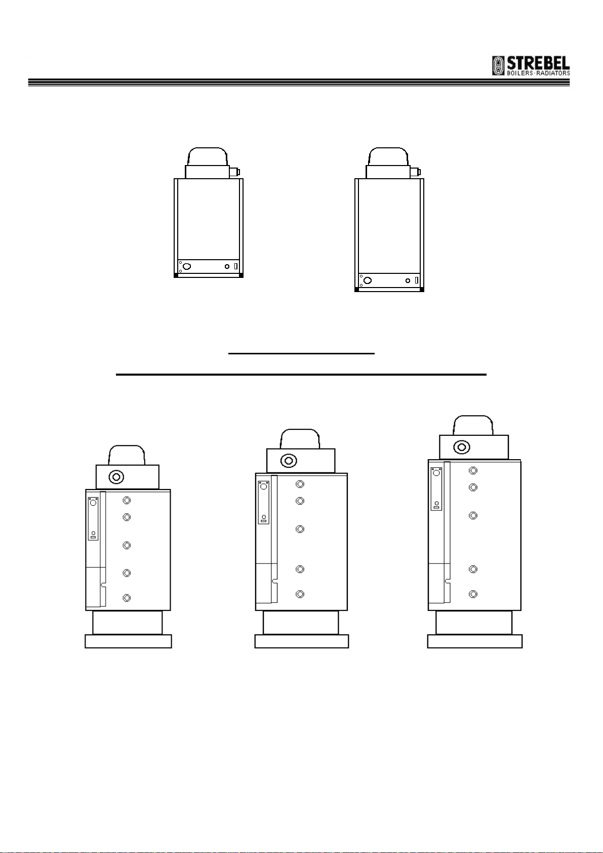
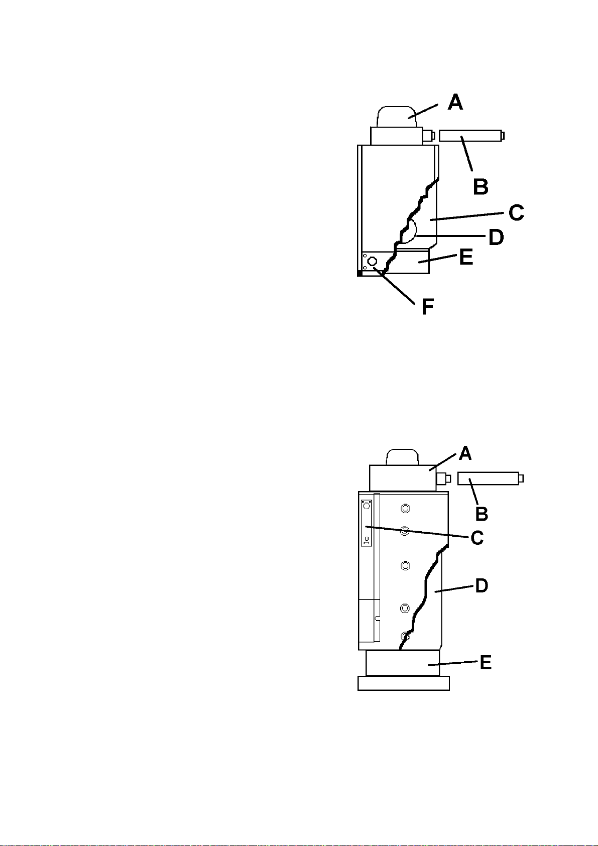
1a: ATI SP 80-120
a-flue hood; b-flue system kit; c-water tank;
d-inspection and cleaning flange;
e-combustion chamber; f-instrument control panel
1.2 PACKAGING CONTENT
For the ATI SP 80 & 120: the appliance is delivered
packaged in a cardboard box with appropriate
protection. Inside there is this booklet, the guarantee
certificate and the wall rosettes for coaxial flue pipes.
For the ATI SP 220, 300 & 400: the appliance is
delivered packaged in a wooden box with appropriate
protection. In a second cardboard box there is the flue
hood (inside which there is the fan for the forced draft
of exhaust gas), the flue outlet carrier, the wall rosette
for coaxial flue pipes and the screws to fix the flue
hood on the appliance and another plastic envelope
containing this booklet and the guarantee certificate.
Picture 1b: ATI SP 220, 300 & 400
a-flue hood; b-flue system kit;
c-instrument control panel; d-water tank;
e-combustion chamber;
4
ATI SP 80, 120, 220, 300, 400 – INSTALLATION INSTRUCTIONS
Sept
-
01
1.3 CONSTRUCTIONAL AND OPERATIONAL
DESCRIPTION
The purpose of the appliance is to allow the exchange
of heat between the gas combustion products, burned
in the combustion chamber, and the water held in the
tank.
The combustion is completely sealed inside the
combustion chamber, because the air supply and
exhaust gas outlet are made out of the room where the
appliance is installed. The sealed combustion chamber
is placed at the bottom of the appliance, under the
water tank. On the top there is the flue hood for the
forced draft of flue gases: a fan, placed after the
combustion chamber, assures the exhaust gas outlet
and the right air supply to the burner for the
combustion. Flue pipes which go through the water
tank, carry the air to the combustion chamber and the
exhaust gas back to the flue hood.
FLUE HOOD
The fan situated in the flue hood provides the air
supply and extracts the products of combustion. The
flue hood rotates through 360° for ease of positioning.
If the fan is not operating correctly or the flue pipes are
obstructed, a pressure switch, placed inside the flue
hood, stops the gas supply to the burner.
WATER TANK
It is made of thick sheet steel and assures great
resistance to pressure. The inside is coated with opal
glass (a vitreous coating baked at over 850°).
This allows a high chemical resistance (unassailable
from organically solvents and many other chemical
substances), excellent abrasion resistance (low
friction) and very good thermal stability (the opal glass
on steel resists up to 500°C; moreover frost and cold
have no effects). Moreover this allows a tank’s longlife and a higher healthy water. Inspection and
cleaning of the tank are allowed by an appropriate
clean our and inspection door.
COMBUSTION CHAMBER
It is situated at the bottom of the appliance, and this is
where the atmospheric burner, ignition and detection
electrodes are housed. The combustion chamber is
completely sealed.
INSTRUMENT CONTROL PANEL
On the instrument control panel there is all that is
required to control and to adjust the normal operating
of the appliance: control thermostat, ON/OFF switch,
lock-out lamp/reset push-button and the therm ometer
FLUE SYSTEM KIT (supplied separately)
It assures the connection between the flue hood and
the termination point, and for the air supply to the
burner. The flue kit required must be selected from the
various kits available, according to installation
requirements:
• horizontal coaxial system, with air supply and flue
outlet through the side wall.
• vertical coaxial system, with air supply and flue
outlet through the roof.
• vertical single wall system, with air supply through
the side wall and flue outlet through the roof.
• horizontal single wall system, with air supply
through the side wall and flue outlet in the chimney.
1.4 CONTROL AND SAFETY DEVICES
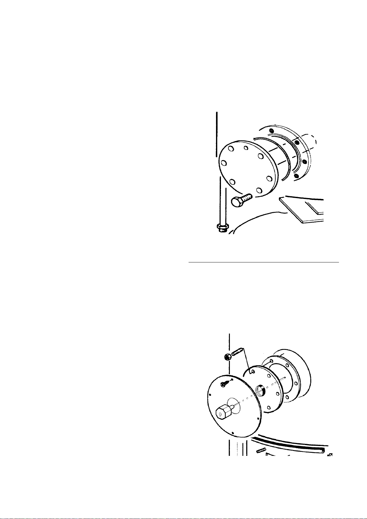
MAGNESIUM ANODE (ATI SP 80 & 120 ONLY)
The water heater is protected against metal-to-metal
corrosion by a magnesium anode. This has to be replaced each year in order to extend the working life of
the appliance. The anode is placed in the inspection
flange.
Picture 2a
Magnesium anode position
On ATI SP 80 & 120
CORREX ELECTRONIC ANODE
(ATI 220, 300 & 400 ONLY)
The water heater is protected against metal-to-metal
corrosion by an electronic anode. This requires a permanent 230 volt electrical supply in order to give full
protection and extend the working life of the appliance. The anode is fitted in a 3/4" connection in the
clean out and inspection flange.
Picture 2b
Correx electronic anode position
on ATI SP 220, 300 & 400

5
ATI SP 80, 120, 220, 300, 400 – INSTALLATION INSTRUCTIONS
Sept
-
01
ELECTRONIC CONTROL BOX
This controls the opening and closing of the gas valve
and the ignition of the burner.
If the pressure switch is in the “no air” position when
the control thermostat calls for heat, the fan is
switched on. When sufficient air flow is proven by the
pressure switch, a pre-purge period elapses before the
built-in ignite and gas valve are energised. The ignition
spark ignites the gas and the resulting flame is
detected by the flame detection electrode. Ignition
sparking is switched off immediately after a flame is
established. If the flame is not established within the
safety time, the control box locks out. In this case, wait
a few seconds and reset the control box, by
depressing the reset push-button on the instrument
panel. A new ignition cycle will start.
CONTROL BOX - TECHNICAL DATA
supply voltage 220/240 V
50/60 Hz
ambient temperature 0 - 60 °C
pre-purge time 30 sec
safety time 10 sec
minimum flame current 0,7 uA
response time off < 1 sec.
The flame sensing is based on the rectification
principle (an AC signal is sent from the control box to
the detection electrode, where it is converted to a DC
signal and returned to the control box).The control box
is approved by Gastec, Holland and VDE and DINDVGW, Germany.
GAS VALVE
For ATI SP 80-120: This is a compact multi-functional
and multi-gas control, with 2 direct-acting solenoid
valves (class B, group 2) with high sealing force. It has
an integral electronic packages for quiet operation with
cushioned solenoid stops, and it incorporates an
adjustable direct acting pressure regulator, and
approved by DIN-DVGW Germany.
Picture 3
Gas Valve for ATI SP 80 & 120
The aluminium body has 3/8” x 3/8” (BSP P.I.) inlet
and outlet and inlet screen (protected from potential
pipe damage). Commissioning and any adjustments
should be carried out by a qualified combustion
engineer. Care should be takes to prevent foreign
matter from entering valve during valve replacement.
MAINTENANCE: the only maintenance operation
allowed is the solenoid replacement, which has to be
carried by qualified personnel only.
GAS VALVE FOR ATI SP 80 – 120
Maximum pressure inlet 50 mbar
Voltage rating 220/240 V 50/60 Hz
Ambient temperature range 0 - 60 °C
Opening time < 0.25 seconds
Closing time < 0.25 seconds
For ATI 220 – 300 – 400 This is a multi-functional and
multi-gas gas control, with double silent
directly operated solenoid valve in class 2, adjustable
pressure regulator and low rate ignition with ignition
rate adjuster (factory set). Tis is approved by BRITISH
GAS (UK) and GASTEC (Holland).
The aluminium body has 1/2” x 1/2” RP UNI-ISO 7 gas
inlet and outlet, inlet and outlet pressure test points
and inlet filter. The solenoids are connected in series,
with a single electrical connector for both.
Commissioning and any adjustments should be carried
out by a qualified combustion engineer. Care should
be takes to prevent foreign matter from entering valve
and ensure that gas flow follows arrow on valve body
during valve replacement.
MAINTENANCE: the only maintenance operation
allowed is the solenoid replacing, which has to be
carried out by qualified personnel only.
Gas Valve for ATI SP 220, 300 & 400
Picture 4
6
ATI SP 80, 120, 220, 300, 400 – INSTALLATION INSTRUCTIONS
Sept
-
01
GAS VALVE FOR ATI SP 220, 300 & 400
TECHNICAL DATA
Maximum pressure inlet 50 mbar
Voltage rating 220/240 V 50/60 Hz
Ambient temperature range 0 - 60 °C
Opening time < 0.25 seconds
Closing time < 0.25 seconds
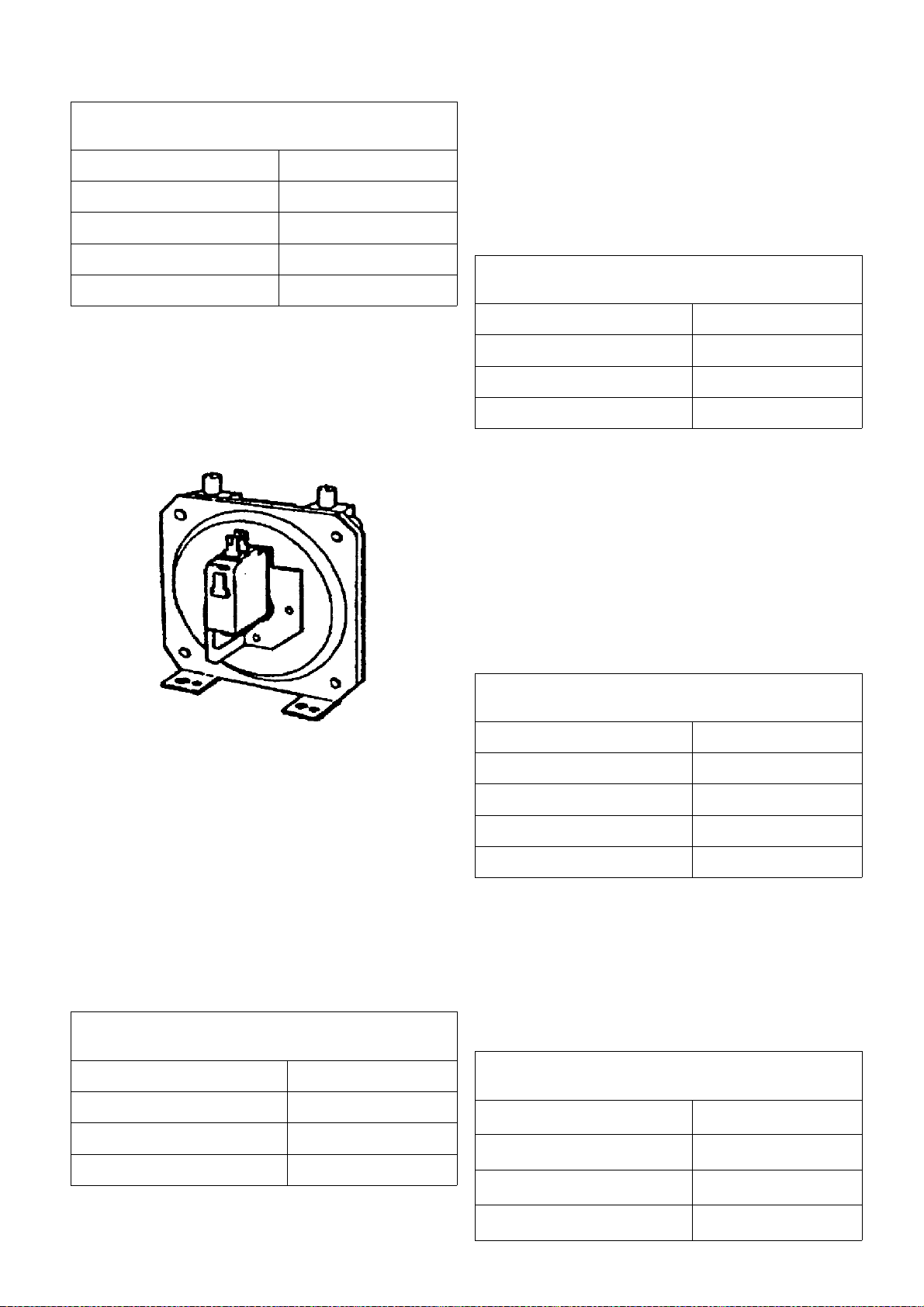
DIFFERENTIAL PRESSURE SWITCH
The pressure switch functions as a (combustion)
airflow supervisor with a safe start
interlock. If the airflow is not enough it will cut-off the
gas flow to the burner. This occurs for a fan failure or
for an obstruction in the combustion circuit.
Differential Pressure Switch
Picture 5
It is placed in the flue hood and it is connected by two
silicon pipes to two probes inside the flue hood, to test
the pressure difference on the flue outlet when the fan
is operating. In front of the device there is an
adjustment screw for setting, which is factory set. It
has three
terminals (common, normally closed NC and normally
open NO).It is approved by UL (USA), TÜV and DINDVGW (Germany).
DIFFERENTIAL PRESSURE SWITCH
TECHNICAL DATA
Maximum sustained pressure 6 mbar
Ambient temperature -10/ + 70°C
Contact terminals resistance < = 300m?
Electrical rating 250V ~ / 1.5A
ADJUSTABLE CONTROL THERMOSTAT 0-70°
This controls the operation of the appliance,
switching the burner on and off, according to the water
temperature set. This is a single pole liquid filled
sensing bulb with operating switch contacts. It is
approved by VDE (Germany) and IMQ (Italy).
ADJUSTABLE CONTROL THERMOSTAT
TECHNICAL DATA
contacts rating 250 V ~/2,5 A
temperature differential 4° ±/- 1°K
max. bulb temperature 150 °C
temperature range 40° / 80°
SAFETY LIMIT THERMOSTAT
Cuts off the burner operating in case the appliance
overheats, caused by control thermostat failure or lack
of circulation. To switch the appliance on again it is
necessary to press the manual reset button. The
cause of the safety lock should be investigated.
For ATI SP 80 & 120: This is a single pole thermostat
with snap action contacts and temperature control by
surface contact.It is approved by VDE (Germany),
SEMKO (Sweden), UL (USA), ASEV (Switzerland),
KEMA (Holland).
SAFETY LIMIT THERMOSTAT (ATI SP 80 & 120)
TECHNICAL DATA
intervention temperature 85°C
tolerance intervention +5° / -5°K
differential 14°K
contacts resistance £ 5 mW
capacity 250 V ~/10A
For ATI 220, 300 & 400: This is a single pole liquid
filled type, temperature limited with manual reset and
positive cut-off in case of capillary breakage. The high
limit temperature is factory set at 90°.It is approved by
VDE and DIN (Germany), SEMKO (Sweden) and IMQ
(Italy
SAFETY LIMIT THERMOSTAT
(ATI SP 220, 300 & 400)
adjustable limit temperature 90°/110°
tolerance +0° / - 6°K
contacts rating 250 V ~/2,5 A
max. bulb temperature 125 °C

7
ATI SP 80, 120, 220, 300, 400 – INSTALLATION INSTRUCTIONS
Sept
-
01
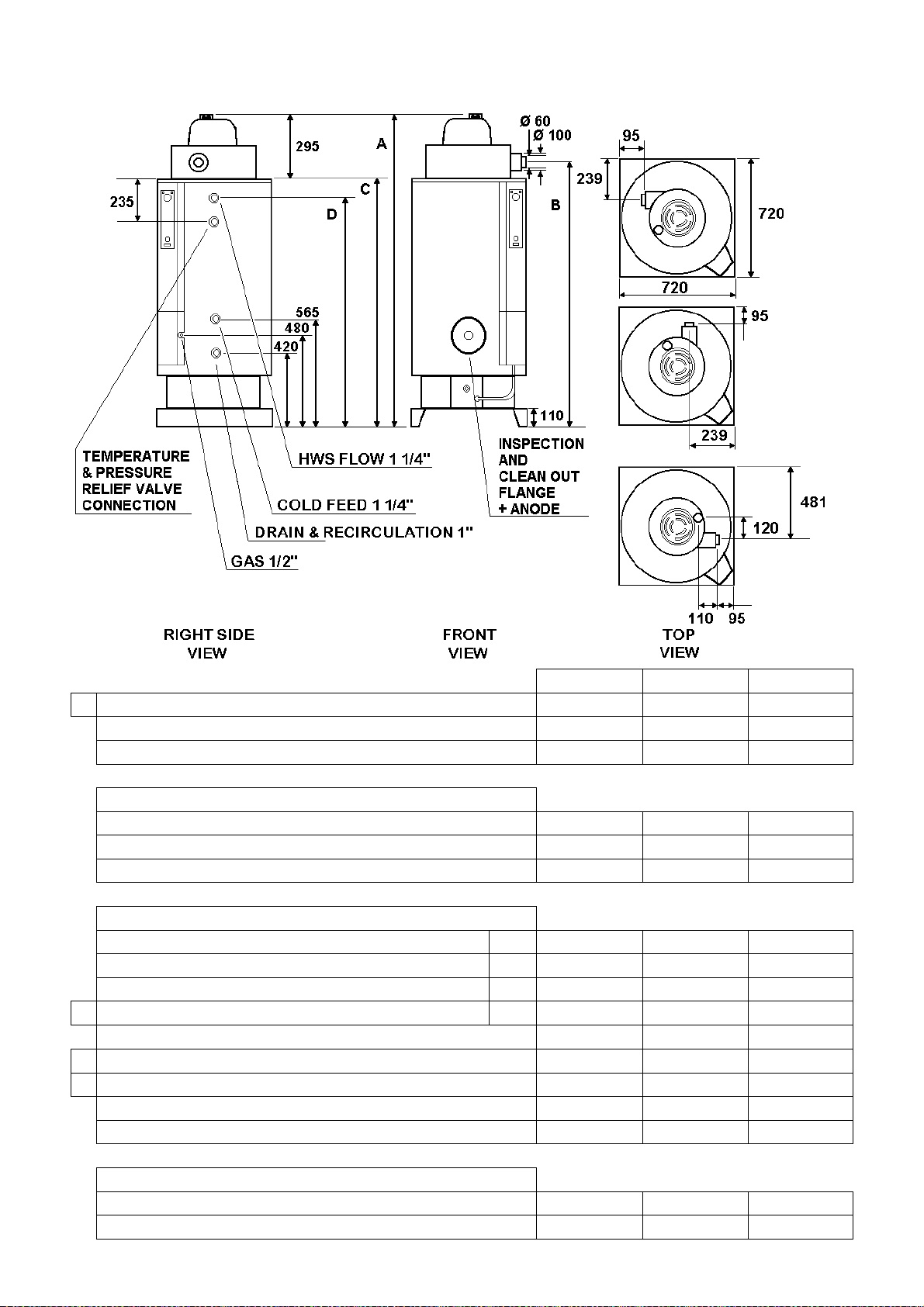
DIMENSIONS AND CONNECTIONS
ATI SP 80 & 120
ATI SP 80 ATI SP 120
OVERALL HEIGHT
A
WIDTH
DEPTH
HEIGHT OF FAN UNIT
HEIGHT WITHOUT FAN UNIT
B
HEIGHT TO FLUE CONNECTION
C
FLUE CONNECTION DIAMETER (INNER PIPE)
FLUE CONNECTION DIAMETER (OUTER PIPE)
FLANGE DIAMETER FOR INSPECTION AND CLEAN OUT AND
ANODE REPLACEMENT
1040 mm 1400 mm
450 mm 450 mm
460 mm 460 mm
190 mm 190 mm
850 mm 1210 mm
895 mm 1255 mm
38 mm 38 mm
60 mm 60 mm
85 mm 85 mm
8
ATI SP 80, 120, 220, 300, 400 – INSTALLATION INSTRUCTIONS
Sept
-
01
DIMENSIONS AND CONNECTIONS ATI SP 220, 300 & 400
A OVERALL HEIGHT 1660 mm 2015 mm 2365 mm
WIDTH 720 mm 720 mm 720 mm
DEPTH 720 mm 720 mm 720 mm
BASE
BASE HEIGHT 110 mm 110 mm 110 mm
BASE WIDTH 720 mm 720 mm 720 mm
BASE DEPTH 720 mm 720 mm 720 mm
HEIGHT FROM FLOOR OF:
GAS CONNECTION 1/2" 480 mm 480 mm 480 mm
COLD WATER FEED CONNECTION 1"1/4 565 mm 565 mm 565 mm
DRAIN & RECIRCULATION CONNECTION 1" 420 mm 420 mm 420 mm
D HOT WATER OUTLET CONNECTION 1"1/4 1300 mm 1655 mm 2005 mm
HEIGHT OF FAN UNIT 295 mm 295 mm 295 mm
B HEIGHT TO FLUE CONNECTION 1495 mm 1840 mm 2190 mm
C HEIGHT WITHOUT FAN UNIT 1365 mm 1720 mm 2070 mm
FLUE CONNECTION DIAMETER (INNER PIPE) 60 mm 60 mm 60 mm
FLUE CONNECTION DIAMETER (OUTER PIPE) 100 mm 100 mm 100 mm
INSPECTION AND CLEAN OUT FLANGE
DIAMETER 120 mm 120 mm 120 mm
HEIGHT FROM FLOOR 460 mm 460 mm 460 mm
ATI SP 220 ATI SP 300 ATI SP 400
9
ATI SP 80, 120, 220, 300, 400 – INSTALLATION INSTRUCTIONS
Sept
-
01
TECHNICAL DATA
ATI SP Model
Storage Capacity Litres 75 115 220 300 400
Nominal Input Btu/h 17,060 17,060 97,242 105,772 105,772
kW/h 5.0 5.0 28.5 31.0 31.0
Nominal Output Btu/h 16,036 16,036 88,029 95,536 95,536
kW/h 4.7 4.7 25.8 28.0 28.0
Combustion Efficiency 94% 94% 92% 92% 92%
10 Minute Output at 54°C
(Storage Water at 60ºC - Cold Water at 10ºC)
Continuous Output With a 44°C Temperature
Difference
Time To Recover With a 44°C Temperature
Difference
Gas Input Rate (Natural Gas G20) m³/h
Injector Diameter mm 2.00 2.00 1.25 1.25 1.25
Gas Pressure At Injector mbar 11.5 11.5 10.0 12.2 12.2
in Wg 4.5 4.5 4 4.8 4.8
Gas Input Rate (LPG G30/31 28-30/37 mbar) kg/h
Injector Diameter mm 1.15 1.15 0.72 0.75 0.75
Gas Pressure At Injector mbar 28.2 28.2 28.2 28.4 28.4
in Wg 11 11 11 11.1 11.1
Electrical Supply For Unit
Electrical Supply For Electronic Anode
Maximum Working Pressure
Minimum Working Pressure bar
Shipping Weight kg 49 74 202 245 286
Filled Weight kg 124 189 422 545 686
Lits/10 mins
Gals/10 mins
Lits/h
Gals/h
mins 44 71 26 34 43
ft³/h
lbs/h
bar
psi
psi
80 120 220 300 400
91
20
91
20
0.53
18.71
0.39
0.85
230 Volt - 50Hz - Single Phase - 3 Amp Fuse
N/A N/A
6
87
0.1
1.5
140
30
91
20
0.53
18.71
0.39
0.85
6
87
0.1
1.5
305
67
502
110
3.01
106.29
2.24
4.93
Permanent 230 Volt- 50Hz
Single Phase -3 Amp Fuse
6
87
0.1
1.5
401
88
568
125
3.28
115.82
2.44
5.37
6
87
0.1
1.5
515
113
568
125
3.28
115.82
2.44
5.37
6
87
0.1
1.5
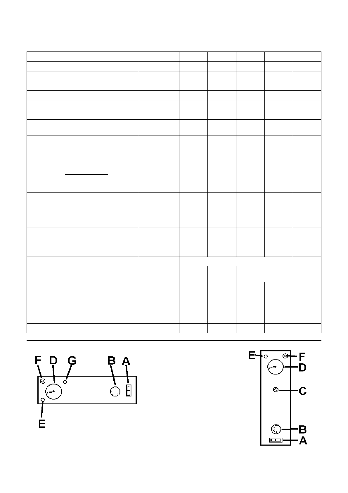
INSTRUMENT CONTROL PANEL
Picture 9a
ATI SP 80-120
A ON/OFF SWITCH
B ADJUSTABLE CONTROL
THERMOSTAT 0-70°C
C SAFETY LIMIT THERMOSTAT
(MANUAL RESET)
D THERMOMETER
E GREEN BURNER (ON) LIGHT
F LOCK OUT LIGHT + RESET
BUTTON
G HOLE FOR INSPECTION
OF THE COMBUSTION
Picture 9b
ATI SP 220-300-400
 Loading...