

Page 1
STREBEL
ASCONA ‘A’ & ‘APV’
ATMOSPHERIC GAS BOILER
INSTALLATION, OPERATING AND
MAINTENANCE MANUAL
JUNE 2000
Page 2

12/06/00Page 2
ASCONA ‘A’ & ‘APV’ INSTALLATION INSTRUCTIONS
SECTION TITLE PAGE
1 GENERAL 5
2 LOCATION 5
3 VENTILATION 5
4 GAS SUPPLY 6
5 FLUE SYSTEM 7
6 WATER CIRCULATION 7
7 INSTALLATION 7
8 ELECTRICAL SUPPLY 8
9 COMMISSIONING AND TESTING 8
10 SERVICING 9
11 FAULT FINDING 10
12 GAS VALVE ADJUSTMENT 11
13 L.P.G CONVERSION 13
14 WIRING DIAGRAM 14
15 USERS INSTRUCTIONS 16
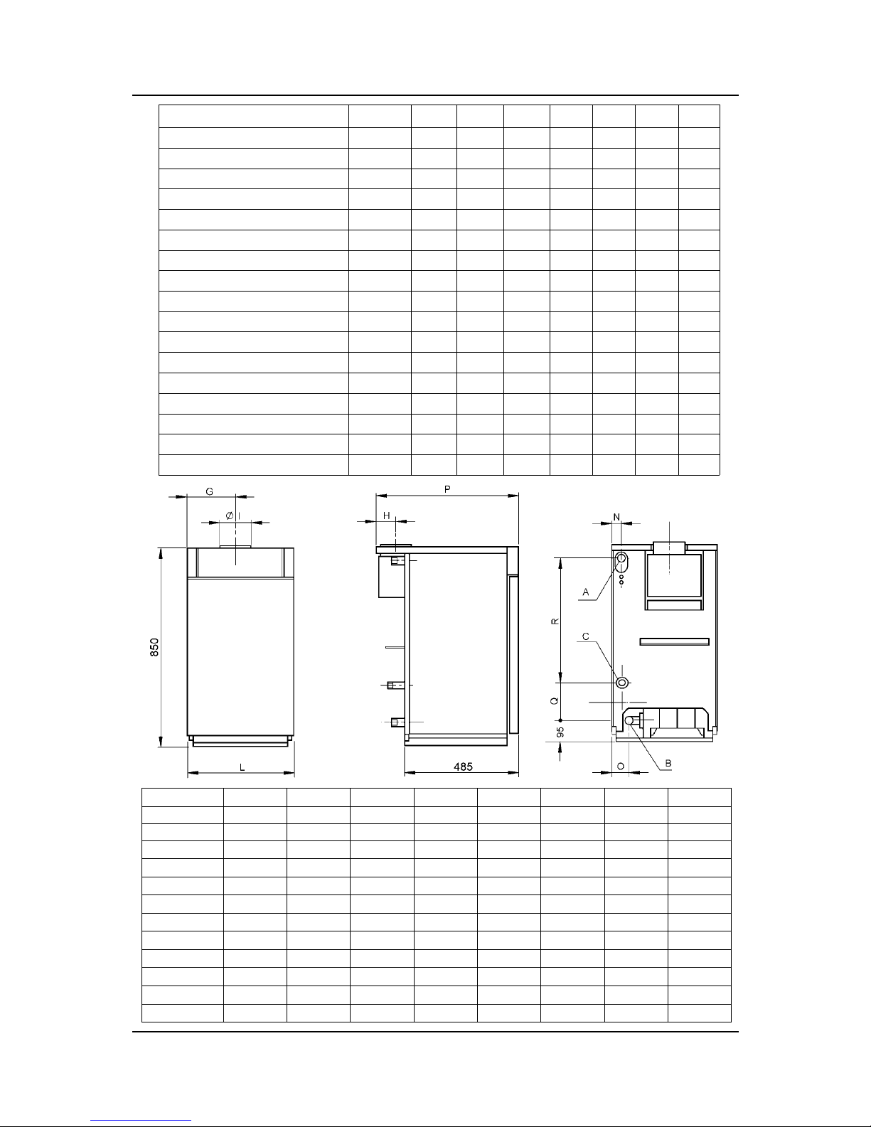
TABLE 1 TECHNICAL DATA ASCONA ‘A’ 3
TABLE 2 TECHNICAL DATA ASCONA ‘APV’ 4
TABLE 3 VENTILATION REQUIREMENTS A3 – A6 6
TABLE 4 VENTILATION REQUIREMENTS A3 – A6 6
TABLE 5 VENTILATION REQUIREMENTS A7 – A9 6
PAGE INDEX
Page 3
12/06/00Page 3
ASCONA ‘A’ & ‘APV’ INSTALLATION INSTRUCTIONS
Type and No of Sections A-3 A-4 A-5 A-6 A-7 A-8 A-9
Nominal output kW 18.2 27.5 37.7 47.1 56.5 66.4 75.6
Nominal input kW 20.2 30.5 42.0 52.3 62.7 73.7 83.8
Supply Pressure – Natural gas mbar 20 20 20 20 20 20 20
Supply Pressure – LPG mbar 37 37 37 37 37 37 37
Burner Pressure – Natural gas mbar 14.8 14.5 13.2 14.5 14.5 14.5 14.5
Burner Pressure – LPG mbar 31.5 30.8 30.3 29.7 29.4 29.1 31
Burner injectors – Natural gas mm 2.6 2.6 2.7 2.6 2.6 2.6 2.6
Burner injectors – LPG mm 1.75 1.75 1.75 1.75 1.75 1.75 1.65
Gas consumption – Natural M³/h 2.33 3.44 4.55 5.63 6.72 7.80 8.87
Gas consumption – LPG Kg/h 1.71 2.52 3.43 4.13 4.93 5.72 6.50
Water Resistance 10ºC differential mbar 9.5 20 36.5 23 34 46 57
Water content Litres 10 12.5 15 17.5 20 22.5 25
Flue gas volume G/s 0.017 0.021 0.026 0.037 0.039 0.053 0.053
Flue gas temperature ºC 106 119 134 117 128 112 120
Electrical supply for unit V/Hz 230/50 230/50 230/50 230/50 230/50 230/50 230/50
Wattage W 40 40 40 40 40 110 110
Shipping weight Kg 87 110 136 164 186 213 234
ASCONA ‘A’ TECHNICAL DATA – TABLE 1
A-3 A-4 A-5 A-6 A-7 A-8 A-9
L mm 365 450 600 750 750 900 900
P mm 600 600 600 650 650 705 705
ØA Flow inches 1" 1" 1" 1¼" 1¼" 1¼" 1¼"
ØB Return inches 1" 1" 1" 1¼" 1¼" 1¼" 1¼"
ØC Gas supply inches ½" ½" ½" ½" ½" 1" 1"
G mm 135 205 205 335 335 405 405
H mm 80 80 90 105 105 125 125
ØI Flue size mm 130 130 150 180 180 220 220
N mm 40 40 115 55 55 55 55
O mm 70 70 150 55 55 55 55
Q mm 160 160 160 160 160 150 150
R mm 540 540 540 540 540 550 550
Page 4

12/06/00Page 4
ASCONA ‘A’ & ‘APV’ INSTALLATION INSTRUCTIONS
A-3 A-4
L mm 365 450
P mm 600 600
ØA Flow inches 1" 1"
ØB Return inches 1" 1"
ØC Gas supply inches ½" ½"
G mm 135 205
H mm 80 80
ØI Flue size mm 130 130
M mm 40 40
ØS mm ½” ½”
Type and No of Sections PVA-3 PVA-4
Nominal output kW 18.2 27.5
Nominal input kW 20.2 30.5
Supply Pressure – Natural gas mbar 20 20
Supply Pressure – LPG mbar 37 37
Burner Pressure – Natural gas mbar 14.8 14.5
Burner Pressure – LPG mbar 31.5 30.8
Burner injectors – Natural gas mm 2.6 2.6
Burner injectors – LPG mm 1.75 1.75
Gas consumption – Natural M³/h 2.33 3.44
Gas consumption – LPG Kg/h 1.71 2.52
Water Resistance 10ºC differential mbar 9.5 20
Water content Litres 10 12.5
Flue gas volume G/s 0.017 0.021
Flue gas temperature ºC 106 119
Electrical supply for unit V/Hz 230/50 230/50
Wattage W 40 40
Shipping weight Kg 94 118
ASCONA ‘APV’ TECHNICAL DATA – TABLE 2
ASCONA ‘APV’ Heating pump curve
Page 5

12/06/00Page 5
ASCONA ‘A’ & ‘APV’ INSTALLATION INSTRUCTIONS
1.0 GENERAL
1.1 The STREBEL ASCONA ‘APV’ & ‘A’ range of Gas Fired Boilers are floor mounted open flued
units for connection to heating and indirect hot water systems.
The Ascona heat exchanger body is constructed of cast iron sections with a stainless steel
atmospheric gas burner suitable for Natural Gas and LPG (site conversion) the boilers as
standard are fitted with electronic ignition. The boilers are fitted with full safety devices including
“Spillage Control System” (SCS) which shuts down the boiler if Spillage is occurring and so
prevents any escape of flue gases out the flue diverter, also on the A-8 & A-9 models there is a
Gas pressure switch for low inlet gas pressure.
The boilers are delivered completely assembled with jackets fitted and fully insulated.
The ASCONA ‘APV’ range is also fitted with three speed circulating pump, expansion vessel for
use with a sealed systems, 3 Bar safety valve, pressure gauge and water fill point (manual).
1.2 The installation of this boiler must be carried out in accordance with the relevant requirements of
the gas safety (installation and use) Regulations 1998, the I.E.E. Wiring Regulations and the
Bylaws of the Local Water Undertaking, and current Building Regulations
Detailed recommendations are contained in the following:
British Standard Code of Practice:
BS 6880 parts 1, 2 & 3 1988.
BS 6700 1987; CP. 342 : Part 2 :
BS 5440 parts 1 & 2 :
BS 5854 : BS. 6644 :
BS 6798 :
BS 6891 and British Gas Publications :- IM/11 Flues for Commercial and Industrial Gas Fired
Boilers and Air Heaters
"The Gas Safety (Installation and Use) Regulations 1998:
It is the law that all gas appliances are installed by CORGI registered contractors in accordance
with the above regulations. Failure to install appliances correctly could lead to prosecution. It is
in your own interest, and that of safety, to ensure that the law is complied with".
2.0 LOCATION
2.1 The boiler must stand on a level non combustible base, which is capable of adequately supporting
the weight of the boiler, water content an any ancillary equipment.
The location chosen for the boiler must permit the provision of a satisfactory flue and termination.
the boiler should be positioned to allow 50 mm between boilers and 500 mm at one end for
access to the pipework etc. 600 mm is required above to clean the flue-ways.
There should be 350 mm at the front of the boiler for maintenance and the draught diverter should
be at least 50 mm clear of the wall behind the boiler.
The location must also permit an adequate space for combustion and ventilation air purposes
(seeSection3on
Ventilation) and adequate space for servicing and air circulation around the
boiler.
3.0 VENTILATION
3.1 It is important that there are sufficient areas of air inlet and ventilation provided to the boiler room
detailed recommendations for air supply are given in BS 5440 part 2 & BS 6644.
Page 6

12/06/00Page 6
ASCONA ‘A’ & ‘APV’ INSTALLATION INSTRUCTIONS
VENTILATION INTO A ROOM
OR INTERNAL SPACE IN CM²
A3 &
APV 3
A4 &
APV 4
A5 A6
HIGH
LEVEL
182 275 378 471
LOW
LEVEL
364 549 756 942
VENTILATION DIRECT TO
OUTSIDE AIR IN CM²
A3 &
APV 3
A4 &
APV 4
A5 A6
HIGH
LEVEL
91 138 189 236
LOW
LEVEL
182 275 378 471
VENTILATION DIRECT TO
OUTSIDE AIR IN CM²
A7 A8 A9
HIGH
LEVEL
277 301 324
LOW
LEVEL
553 602 648
TABLE3 TABLE4
TABLE5
3.3 Mechanical Ventilation.
The minimum quantity of air required for combustion and boiler house ventilation shall be supplied at a minimum flow rate in accordance with BS 6644.
All air inlet and extract fans shall be fitted with automatic controls causing safety shut-down or
lockout of the boiler(s) in the event of the inlet or extract air flow failing.
4.0 GAS SUPPLY
4.1 An existing meter should be checked preferably by the Gas Supplier, to ensure the meter is
adequate to deal with the rate of gas required.
4.2 Pipework from the meter to the boiler must be of adequate size. Pipes of smaller size than the
boiler inlet gas connection should not be used. All gas pipework should be fitted and on completion of installation tested, in accordance with BS 6891 : IGE/UP/2 Gas Installation Pipework,
Boosters and Compressors on Industrial and Commercial Premises.
4.3 Gas supply connections is as follows:
Ascona APV 3 & PV 4 = 1/2" BSP
Ascona A3,A4,A5,A6&A7=1/2"BSP
Ascona A 8 & A 9 = 1" BSP.
4.4 A gas service cock must be fitted immediately adjacent to the boiler.
Table 5 refers to the ventilation requirements (direct to outside air) for the Ascona A7 – A9 boilers.
Table 3 refers to the ventilation requirements (to internal space) for the Ascona A3 – A6. Table 4
refers to ventilation direct to outside for the Ascona A3 – A6.
Page 7

12/06/00Page 7
ASCONA ‘A’ & ‘APV’ INSTALLATION INSTRUCTIONS
5.0 FLUE SYSTEM
5.1 Detail recommendations for flueing are given in B.G.C. Publications:- “Flues for commercial
and Industrial Gas Fired Boilers and Air Heaters” 1M/11.
Reference should also be made to BS. 5440 Part 1 : BS. 6644 where applicable.
The following notes are intended to give general guidance.
5.2 The nominal flue size should not be less than that of the boiler flue connection, and must be at
least equivalent to a vertical height above the boiler outlet of 1 M (3 ft 3 in), due allowance
being made for any horizontal or inclined length, and consideration being given to the position
of the outlet.
The boiler flue hood is not load bearing and the flue must be supported independently. The
flue should be easily disconnected for servicing.
6.0 WATER CIRCULATION SYSTEM
6.1 Flow and return connections are from the back of the boiler with BSP connections.
6.2 In combined heating and hot water systems the hot water storage vessel must be of the
indirect cylinder or calorifier type.
6.3 The boiler maximum working pressure is 4 Bar (58 Psi) for ‘APV’ models and 4 Bar (58 Psi) for
‘A’ models which includes pump circulation head. The minimum head being 1 meter above the
top of the boiler.
6.5 Hydraulic Resistance and Flow Rates
The differential temperatures across the flow and return water connections to the boiler is
recommended as 10°C temperature difference (Max. temperature difference 20°C).
Water flow rates and water pressure drops across the boilers are detailed on Table 1.
6.6 If three-way mixing or diverting vales are installed in the systems they should not be of such a
type that the flow through the boiler is totally closed. If such valves are used, a by-pass should
be fitted.
7.0 INSTALLATION
7.1 The boiler is delivered assembled, on a wooden crate with protection for transportation and
site positioning.
Do not remove protection before final positioning.
7.2 The boiler jackets and control panel are fitted.
7.3 The following minimum clearances around the boiler, for installation and servicing purposes,
are recommended:
Above the top of the boiler (space for cleaning the flueways) 600mm, one side of the boiler
should allow access of 500mm.
7.4 In addition a minimum clearance of 350mm should be available at the front of the boiler to
enable servicing to be carried out.
Page 8
12/06/00Page 8
ASCONA ‘A’ & ‘APV’ INSTALLATION INSTRUCTIONS
8.0 ELECTRICAL SUPPLY
8.1 The electrical supply should be 220V, 50Hz, and fused at 3 amps. A suitable independent
switch fuse should be installed for each boiler, adjacent to the boiler.
WARNING : This appliance must be earthed.
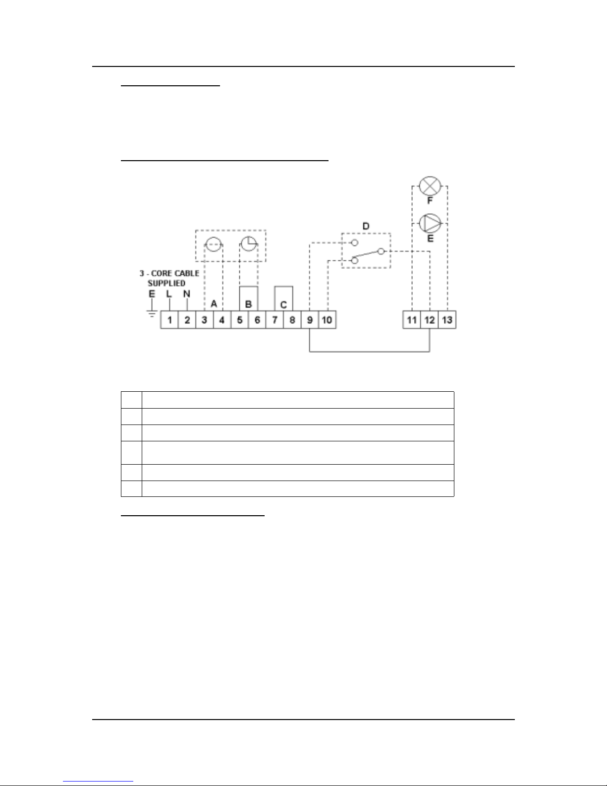
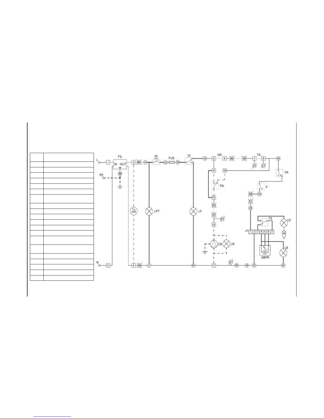
8.2 ASCONA ‘A’ & ‘APV’ Electrical schematic diagram
LEGEND
9.0 COMMISSIONING ANDTESTING
Before commencing to commission the boiler, check the following:-
9.1 Electrical
Electrical supply is switched off.
All electrical connections are sound and correctly made.
Electrical system is correctly earthed.
9.2 Gas Supply
Gas supply is purged of air, and tested for soundness as described in BS. 6891 : IGE/UP/2
Gas Installation Pipework, Boosters and Compressors on Industrial and Commercial Premises.
All appliance gas cocks are turned off.
Gas supply is on at meter.
A LIVE CONNECTION TO TIME CLOCK
B EXTERNAL TIME CLOCK : ON / OFF CONTROL
C ROOM THERMOSTAT / REMOTE ON / OFF CONNECTIONS
D
THERMAL PUMP OVERRUN – NOT SUPPLIED
(LINK BETWEEN TERMINALS 9 & 10 TO BE REMOVED IF DEVICE FITTED)
E BOILER CIRCULATING PUMP CONNECTIONS (PUMP INCLUDED WITH APV MODELS )
F BOILER CIRCULATING PUMP RUN LAMP (APV MODELS ONLY)
Page 9

12/06/00Page 9
ASCONA ‘A’ & ‘APV’ INSTALLATION INSTRUCTIONS
9.3 Water
Boiler and system have been flushed through and are filled, and circulating pumps operational.
Flow and return valves are open.
9.4 To Test Soundness of Safety Shut-Off Valve
1 Ensure that the main gas cock and electricity supply are turned OFF.
2 Remove plug from pressure test point on inlet side of the safety shut off-valve and connect
pressure gauge.
3 Turn ON main gas cock to pressurise the system up to the seat of the safety shut-off valve.
4 Turn OFF main gas cock, leave for two minutes checking for any drop in pressure on the
gauge. If any pressure loss is observed, re-pressurise by opening and closing the main
gas cock, and test the assembly for leaks using a leak detector solution.
5 If no external leaks are detected and loss of pressure occurs, this is the result of a let-by at
the safety shut-off valve.
9.5 To Light The Boiler
9.5.1 Fully Automatic Models (see Fig. 2 & 3)
1 Connect pressure gauge to burner pressure test point.
2 Switch on mains electrical supply.
3 Turn ON main gas cock.
4 Depress reset button on limit thermostat to ensure that it is “made”.
5 Set control thermostat to required temperature and push button “I” (on control panel) to the
ON position
6 After switching on, ignition spark should appear, followed by ignition of the main burner at
pilot setting . If flame is not established control box will lock out in approximately 5
seconds. This may occur in initial start due to air in the gas line. The control box may be
reset after a delay of approximately 15 seconds by pressing the red button (refer to page
16, No 11) on the control panel, the red light should go out.
7 When pilot flame is satisfactory the gas valve will open to main flame.
8 Check main burner pressure (as per TABLE 1). Adjust burner pressure on gas control if
necessary. Burner pressure should be rechecked after about 30 minutes of operation and
adjusted if necessary.
9 Switch Off electrical supply with button “I” (on control panel). Check that main burners are
extinguished. Remove pressure gauge and replace plug in test point.
9.6 All Models
After lighting the boiler as described above, the operation of the thermostat should be
checked. All gas lines should be re-checked for soundness, using a leak detector solution.
The gas rate should be checked at the meter, but unless this differs significantly from the rated
heat input quoted in TABLE 1, the setting pressure given should be maintained.
9.7 LPG
If gas conversion is required refer to section 13.0
10.0 SERVICING
Before servicing the boiler, switch off electricity supply and then turn off main gas cock.
Page 10

12/06/00Page 10
ASCONA ‘A’ & ‘APV’ INSTALLATION INSTRUCTIONS
10.1 To Clean Boiler
1 Remove jacket front panel.
2 Disconnect leads for ignition and probe electrodes
3 Remove nuts retaining burner door and assembly.
4 Withdraw burner assembly from boiler.
5 Remove jacket top panel and insulation.
6 Remove the access plate from the top of flue hood.
7 Clean burner
8 Clean boiler flueways from the top with flue brush. After cleaning, sweep all debris from
under the boiler.
9 Check ignition and probe electrodes (fully automatic models) for correct alignment.
10 Re-assembly is a reversal of the above procedure
10.2 To Clean Burners
1 Remove burner assembly from boiler
2 Release screws holding burners.
3 Lift burners at rear and withdraw off injectors.
4 Brush out inside of burners and clean off outside surfaces.
5 Inspect injectors and sealing washers on manifold. Replace if necessary.
6 Re-assembly is reversal of the above procedure.
7 Check electrical connections to electrodes, and electrodes for correct alignment.
10.3 Test Soundness of Safety Shut-Off Valve
Proceed as detailed in 9.4
10.4 Re-commission boiler as described in Section 9.5.1
11.0 FAULT FINDING
1. Boilers does not attempt to light. Control box does not lock out
(a) No electrical supply to boiler, time switch and other external controls.
(b) Limit thermostat tripped.
(c) Control thermostat set to low.
(d) Control fuse blown.
(e) Faulty thermostat connections.
(f) Faulty control box.
2. Ignition sparks. Pilot stage does not light and control box locks out.
(a) Gas supply turned off at meter.
(b) Air in gas supply line.
(c) Solenoid valve or connections.
(d) Lead not plugged into junction box.
3. No ignition spark. Control box lock out.
(a) H.T. lead disconnected or faulty.
(b) Ignition electrode incorrectly set. Distance between ignition and ground electrode
should be about 3 mm.
(c) Faulty electrode.
(d) Faulty igniter or connections.
(e) Faulty control box.
Page 11
12/06/00Page 11
ASCONA ‘A’ & ‘APV’ INSTALLATION INSTRUCTIONS
4. Pilot stage lights, Control box locks out.
(a) Probe lead not connected to electrode.
(b) Earth lead to burner not connected.
(c) Loose connections on probe lead or earth lead in junction box, control panel or
plugs and sockets.
(d) Faulty Control box.
(e) No earth connection on incoming supply.
Note: The probe circuit may be tested with a micro ammeter connected in the probe
lead. A reading of at least 10 micro-amps should be recorded when the burner is alight.
5. Pilot stage lights. Main burners do not light. Control box does not lock out.
(a) Faulty connections to main valve.
(b) Faulty main gas valve.
(c) Faulty control box.
6. Noisy burner ignition
(a) Improper distance between electrode and burner.
(b) Faulty electrical connection of the electrode.
(c) Low gas pressure at the burner.
11.2 All Models
1. Presence of flue gases in the room.
(a) Flue size inadequate.
(b) Restriction in the flue.
2. Presence of unburnt fuel in the room.
(a) Boiler needs cleaning.
(b) Insufficient room ventilation.
3. Early soot formation in the boiler.
(a) Excessive consumption.
(b) Insufficient air supply.
4. Condensation
(a) Insufficient boiler output
(b) Boiler control thermostat setting to low.
(c) Main burner pressure to low.
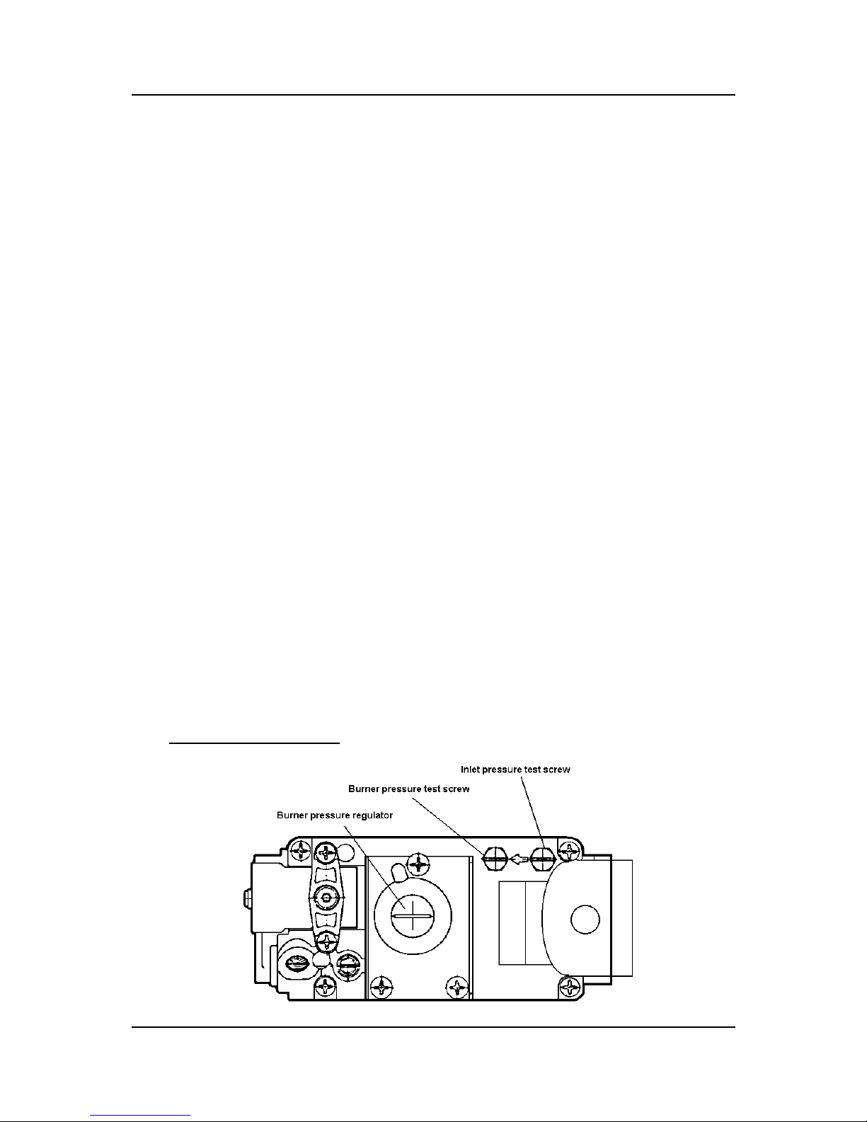
12.0 GAS VALVE ADJUSTMENT
Page 12
12/06/00Page 12
ASCONA ‘A’ & ‘APV’ INSTALLATION INSTRUCTIONS
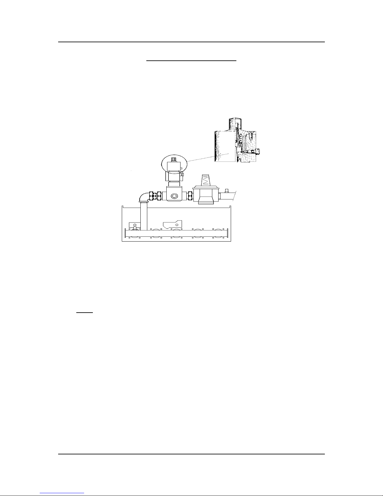
ELEKTROGAS VM-L GAS VALVE
12.1 Slow Opening and Fast Closing Valve with Hydraulic Damper and Flow - Rate Control
• Slow opening time : It can be regulated from a fast speed of 4 sec, to a slow speed of 25
sec. (Valves are delivered with a standard opening time of 10 - 12 seconds).
• Initial fast opening, followed by a slow opening : it can be regulated from 0 to 100 % of
the whole lift.
12.2
A Opening Time Regulation
Slow opening valves are supplied with an opening time of 10 - 12 seconds.
By fully unscrewing the speed adjustment screw (anti-clockwise) the valve will open quickly in
about 4 seconds.
By gradually turning the speed adjusting screw (clockwise) the opening time can be slowed up
to about 25 - 30 seconds.
NOTE
: Remove the red plastic cap to carry out following settings.
12.3
B Regulation of an Initial Quick - Opening Interval Followed by a Slow - Opening Interval
The initial quick interval can be regulated from 0 to 100 % of the whole valve movement, by
acting on the slow opening adjustment screw.
Valves are supplied with the screws completely closed and therefore with a slow shutter run.
When the screw is in a closed position and then gradually opened (anti-clockwise), each complete turn is equal to an initial part of the fast run of 1 mm.
C Flow Regulation
The flow regulation screw (located inside screw B) stops the shutter, which can be stopped at
any point of the run. When the regulation screw is in the closed position (shutter stopped
against the valve seat with zero flow) and is gradually opened (anti-clockwise) the shutter can
be raised 0.8 mm at each complete turn.
Page 13
12/06/00Page 13
ASCONA ‘A’ & ‘APV’ INSTALLATION INSTRUCTIONS
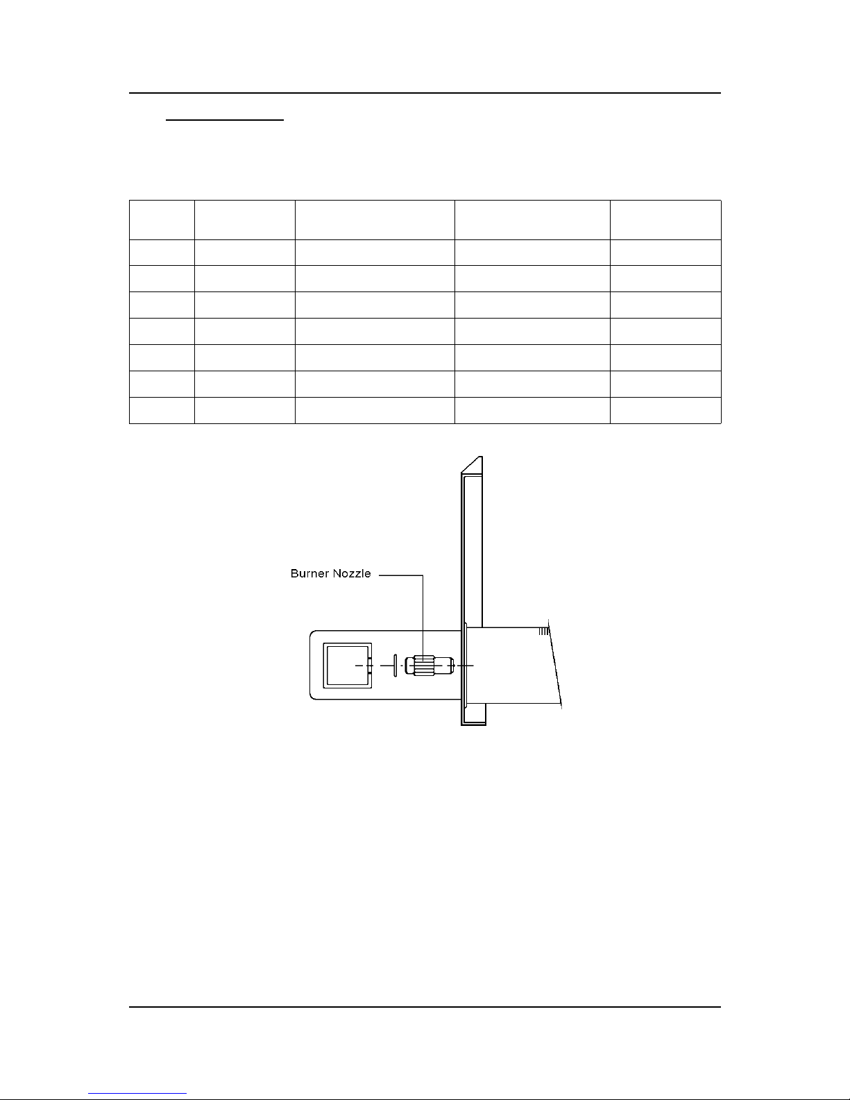
13.0 LPG CONVERSION
The boilers are supplied as standard to be run on natural gas. Should it be necessary to
convert the boiler to LPG the following operations must be carried out :
1 Remove jacket front panel.
2 Switch off electrical supply.
3 Turn off main gas cock.
4 Substitute the injectors on the main burner.
5 Nova Sit 822 gas valve : Remove the burner-pressure regulator cover and screw the
governor spring fully in, replace the cover with blank supplied. Elektrogas VM-l gas valve :
Replace the governor spring with the one supplied
6 Test for soundness.
7 Re-commission boiler as described in section 11. Using LPG burner pressure as stated in
Table 1.
NOTE : The gas supply pressure to the boiler shouldnot exceed the pressure as stated
in Table 1.
BOILER
MODEL
PART
NUMBER
INJECTORS PER KIT
&INJECTORØ
INJECTORS PER
BOILER
KITS
NECESSARY
A–3 6-P435006 4 / 1.75 2 1
A–4 6-P435006 4 / 1.75 3 1
A–5 6-P435006 4 / 1.75 4 1
A–6 6-P435006 4 / 1.75 5 2
A–7 6-P435006 4 / 1.75 6 2
A–8 6-P435006 4 / 1.75 7 2
A–9 6-P435007 4 / 1.65 8 2
Page 14
12/06/00Page 14
ASCONA ‘A’ & ‘APV’ INSTALLATION INSTRUCTIONS
Terminals 7 and 8 are boiler control circuit
CIR Heating Circulation PumpConnections
(Supplied with APV models only)
FIL Noise Suppresser
FUS Fuse
IG BoilerOn/OffSwitch
J1–J8 Control Box Connections
LB Burner Lock-out Lamp
LBP Boiler Lockout Lamp & Reset Button
LC Heating Circulation Pump‘On’ Lamp
(Fitted onAPV models only)
LF Flue Spillage Lamp
LPT Mains Power Indicator Lamp
LS High Limit Lock Out Lamp
OR External Time ClockConnections
P Low GasPressure Switch (A8 &A9)
SBPR Burner Lockout LED & Reset Button
TA Room Thermostat - On/Off Control
Connections
TAI Thermal Pump Overrun Thermostat
(Not supplied)
TF Flue Spillage Thermostat Reset Button
TR Boiler Control Thermostat
TS High Limit Thermostat
VG Main Gas Valve Solenoid
VP Safety Gas ValveSolenoid
ASCONA ‘A’ & ‘APV’ Wiring Diagram
Page 15
12/06/00Page 15
ASCONA ‘A’ & ‘APV’ INSTALLATION INSTRUCTIONS
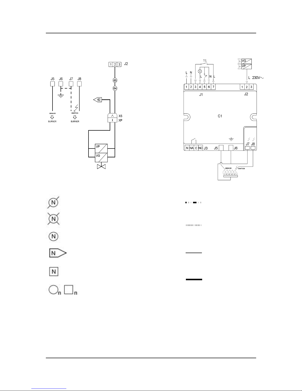
Connector pole for exchangewith printed circuit
of domestic water
Connector pole of Clima control
General connector pole
Link for electrical connector referred to pole ’N’
The direction of the arrow indicates the following
position(totherightorthepreviousare(tothe
left) ofthepole
Terminal board pole with screw connection
Number of ’N’ links of the pole
Optional connections
Terminal Links
Printed circuit board
Wire connections
Page 16
12/06/00Page 16
ASCONA ‘A’ & ‘APV’ INSTALLATION INSTRUCTIONS
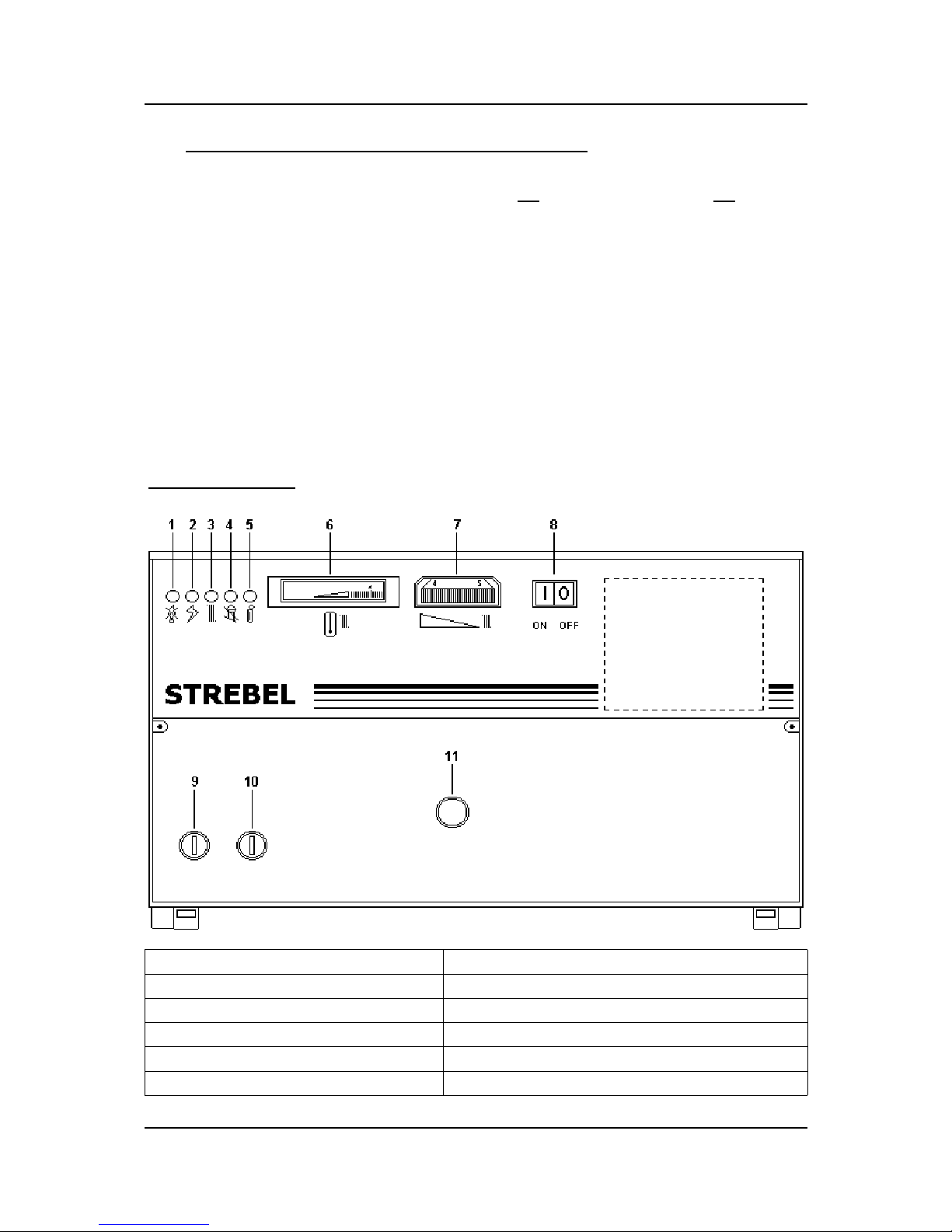
15.0 USERS OPERATING AND MAINTENANCE INSTRUCTIONS
To light the Boiler
1 Check that the boiler gas supply valves are turned ON
and that the gas supply is ON at the
meter.
2 Set the thermostat to the required temperature.
3 Switch on the electricity supply.
4 Pilot burner will light followed by main burners.
5 If red lock out light shows on control panel (No1), reset by pressing red light (No11) after
approximately one minute, then the red light light will go out and boiler will restart.
If the boiler malfunctions repeatedly contact a competent boiler servicing engineer
To shut down Boiler.
1. Switch OFF electricity supply
2. If shutting down for an extended period, also turn OFF the gas supply isolating valve.
Maintenance
We recommend that the boiler is serviced at least annually by a competent boiler servicing engineer
Control Panel Layout
1. Burner Lockout Lamp 7. Boiler Control Thermostat
2. Run Lamp 8. On / Off Switch
3.Heating Pump Lamp *9. High Temperature Limit Thermostat Reset*
4.Flue spillage Lamp *10. Flue Gas Spillage Thermostat Reset*
5.High Temperature Limit Lamp 11. Burner Lockout LED & Reset Button
6.Boiler Thermometer * Remove cover and press button
Page 17

Page 18

STREBEL LTD
1F ALBANY PARK INDUSTRIAL ESTATE
FRIMLEY ROAD, CAMBERLY
SURREY GU25 2PL
TELEPHONE : (01276 685422)
FAX : (01276 685405)
E-MAIL : [email protected]
WEB SITE : www.strebel.co.uk
THE COMPANY RESERVES THE RIGHT TO CHANGE SPECIFICATIONS AND DIMENSIONS WITHOUT NOTICE
Feb-00E & O.E
 Loading...