

Installation manual
for the authorised specialist
Turbotec lambda control 20-100 kW
20-30, 40S-70 40, 50L – 100L
12/2014

READ THE INSTRUCTION BOOKLET AND THESE SUPPLEMENTARY
INSTRUCTIONS CAREFULLY BEFORE INSTALLATION
These supplementary instructions together with those further in the instruction booklet
cover the basic principles to ensure the satisfactory installation of the boiler, although
detail may need slight modification to suit particular local site conditions.
In all cases the installation must comply with current Building Regulations, Local Authority
Byelaws and other specifications or regulations as they affect the installation of the boiler.
It should be noted that the Building Regulations requirements may be met by adopting the
relevant recommendations given in British Standards BS 8303, BS EN 15287-1:2007 as an
alternative means to achieve an equivalent level of performance to that obtained following
the guidance given in Approved Document J.
British Standards BS 6700, BS EN 14336:2004: Heating Systems in Buildings. Installation
and commissioning of water based heating systems. BS EN 12828: 2003; Heating Systems
in Buildings. Design of water based heating systems. BS EN 12831: 2003; Heating Systems
in Buildings. Method for calculation of the design heat load. All as applicable to the
appliance.
Please note that it is a legal requirement under England and Wales Building Regulations
that the installation of the boiler is either carried out under Local Authority Building Control
approval or is installed by a Competent Person registered with a Government approved
Competent Persons Scheme. HETAS Ltd operate such a Scheme and a listing of their
Registered Competent Persons can be found on their website at www.hetas.co.uk.
CO Alarms:-
Building regulations require that when ever a new or replacement fixed solid fuel or
wood/biomass appliance is installed in a dwelling a carbon monoxide alarm must be fitted
in the same room as the appliance. Further guidance on the installation of the carbon
monoxide alarm is available in BS EN 50292:2002 and from the alarm manufacturer’s
instructions.
Provision of an alarm must not be considered a substitute for either installing the appliance
correctly or ensuring regular servicing and maintenance of the appliance and chimney
system.

HEALTH AND SAFETY PRECAUTIONS
Special care must be taken when installing the boiler such that the requirements of the Health and
Safety at Work Act are met.
Handling
Adequate facilities must be available for loading, unloading and site handling.
Fire Cement
Some types of fire cement are caustic and should not be allowed to come into contact with the skin. In
case of contact wash immediately with plenty of water.
Asbestos
This boiler contains no asbestos. If there is a possibility of disturbing any asbestos in the course of
installation then please seek specialist guidance and use appropriate protective equipment.
Metal Parts
When installing or servicing this boiler care should be taken to avoid the possibility of personal injury.

BOILER PERFORMANCE
Refer to the main instruction further in this manual for details of the boiler’s performance.
PREPARATORY WORK AND SAFETY CHECKS
IMPORTANT WARNING
This boiler must not be installed into a chimney that serves any other heating appliance.
There must not be an extractor fan fitted in the same room as the boiler as this can cause the boiler to
emit fumes into the room.
Chimney
In order for the boiler to perform satisfactorily the chimney height must be sufficient to ensure an
adequate draught of approximately 10 - 15 Pa so as to clear the products of combustion and prevent
smoke problems into the room.
NOTE: A chimney height of not less than 4.5 metres measured vertically from the outlet of the boiler to
the top of the chimney should be satisfactory. Alternatively the calculation procedure given in EN 133841 may be used as the basis for deciding whether a particular chimney design will provide sufficient
draught. Ensuring the minimum chimney draught is responsibility of the Chimney specialist appointed.
The outlet from the chimney should be above the roof of the building in accordance with the
provisions of Building Regulations Approved Document J.
Because the boiler runs at high efficiencies, the temperature of the flue gases is at times lower than
conventional solid fuel appliances. Although it is not classed as a condensing appliance, the low flue gas
temperature results in condensation occurring within the flue. Any chimney flue system must therefore
be able to withstand the effects of condensate and operate under wet conditions (designation letter W).
In addition it should be soot fire resistant and able to withstand the corrosive effects of flue products
generated by solid fuels (designation G and 3 respectively). If installation is into an existing masonry
chimney then it will require re-lining with a liner meeting the specification described above. Existing
concrete or clay lined chimneys are not suitable for this boiler and must be lined as described above. All
installations must be in accordance with Building Regulations Approved Document J.

Any existing chimney must be clear of obstruction and have been swept clean immediately before
installation of the lining system. Where the chimney is believed to have previously served an open fire
installation it is possible that the higher flue gas temperature from a closed appliance may loosen
deposits that were previously firmly adhered, with the consequent risk of flue blockage. It is therefore
recommended that the chimney be swept a second time within a month of regular use after installation.
If there is no existing chimney then any new system must be to the designation described above
and in accordance with Building Regulations Approved Document J.
A single wall metal fluepipe is suitable for connecting the boiler to the chimney but is not
suitable for use as the complete chimney. The chimney and connecting fluepipe must have a
minimum diameter of 150 mm and its dimension should be not less than the size of the outlet
socket of the boiler.
Any bend in the chimney or connecting fluepipe should not exceed 45. 90 bends should not be used.
Combustible material should not be located where the heat dissipating through the walls of fireplaces or
flues could ignite it. Therefore when installing the boiler in the presence of combustible materials due
account must be taken of the guidance on the separation of combustible material given in Building
Regulations Approved Document J and also in these boiler instructions.

2
Dear Installer,
The Turbotec central heating
boiler has been subjected to
type and performance testing by
the officially authorised testing
bodies Wieselburg, TGM Vienna
and TÜV Bavaria. All boilers
below 45kW are MCS Approved.
According to the test report, the
Turbotec complies with the
applicable requirements of
EN303-5 for wood fuel.
The Turbotec lambda control is a
highly developed product, which
is not to be judged by
conventional standards and for
the installation of which certain
special features need to be
taken into account. Therefore,
we request that you follow the
instructions below precisely.
Compliance with the installation
instructions is a prerequisite for
trouble-free operation and
guarantee. Please consider that
errors during the installation
sooner or later can lead to
difficulties with approval
authorities, to malfunctions or
even to damage; i.e. in all cases
to customer’s complaints.
Moreover, subsequent
rectification is always more
expensive than a proper, careful
implementation right from the
start. A commissioning protocol
is included with the delivery.
It must be our common goal to
hand over to the customer a
correctly operating, highly
efficient system, every unit and
part of which functions as
expected.
In order to attain this goal, you
have to make a very significant
contribution – we wish you every
success in doing so.
Best regards
Strebel Ltd
Unit 1F Albany Park Industrial Estate, Frimley, Camberley
Tel: 01276 685422
Fax: 01276 685405
Email: info@strebel.co.uk
Thermostrom
Energietechnik Gesellschaft mbH
A-4407 Steyr-Dietachdorf, Ennser Strasse 91
Tel. 0043-7252 / 382 71
Fax 0043-7252 / 382 73 25
Email: thermostrom@strebel.at

3
Overview
General instructions
Area of use/scope of delivery
Overview General instructions................................................. 3
Illustration of boiler types 20-70............................... 4
Illustration of boiler type 60 L................................... 5
Boiler technical data................................................ 6
Boiler dimensions.................................................... 7
Control technical data.............................................. 8
Boiler room/air supply/installation site …..……….... 9
Checks following transport....................................... 9
Assembly Assembly of the cladding with insulation………….. 10
Flue......................................................................... 11
Mounting the air regulation units............................. 11
Mounting the induced draft fan….............................11
Filling and draining.................................................. 11
Heating connections.................................................11
Raising the return temperature............................... 12
Thermal discharge safety device..............................12
Mounting the O2 probe and exhaust fume
sensor.......................................................................12
Mounting the storage tank sensor .......................... 13
Mounting the hydraulic unit .................................... 13
Mounting the control …........................................... 13
Hydraulic diagrams - overview ............................... 14
Hydraulic diagram – system 3 ................................ 15
Electrical connection diagram ................................ 15
System 3................................................................. 16
Functional description ............................................ 16
Important instruction .............................................. 16
Hydraulic diagram – system 3.1 ............................. 17
Electrical connection diagram ................................ 17
System 3.1.............................................................. 18
Function description …........................................... 18
Important instruction .............................................. 18
Settings for system 3 ..............................................19
Table for noting system settings ............................ 20
Aggregate test ...................................................... ..20
Commissioning Instruction/commissioning/handover ...................... 21
Commissioning the control ..................................... 21
Setting the boiler water temperature ...................... 21
Commissioning the boiler........................................ 22
Heating up/adding fuel ........................................... 22
Circuit diagram ....................................................... 23
Short operating instructions: lambda control OFF .. 24
Short operating instructions: lambda control ON..... 25
Maintenance Boiler maintenance ................................................ 26
Malfunctions Troubleshooting ..................................................... 26
General instructions
Installation, assembly, electrical
connections and first commissioning
are tasks for a qualified expert. He is
responsible for ensuring proper
implementation.
Explanation of our warranty
conditions.
We have to exclude our warranty for
damages occurring due to the
following reasons:
- inappropriate or improper use
- incorrect assembly resp.
commissioning by the purchaser or
a third party, including the fitting of
third party parts
- operation of the system with
excessive pressure.
The prerequisites for the provision of
a warranty are:
- correct operation of the boiler
- operation of the system within the
performance limits specified by the
manufacturer
- use of suitable fuels.
- the return of the completed
commissioning protocol to
thermostrom Energietechnik
Gesellschaft mbH.
Instruction for the user
The system will retain its safety and
functions if it is serviced regularly
every year.
Fields of use
Boilers from the Turbotec series are
suitable and approved for use as heat
generators in hot water heating
systems with a permissible flow
temperature of up to 100 °C. They
can be installed in open and closed
systems according to DIN 4751,
sheets 1 and 2, or ÖNORM B 8130
and B 8131.
Scope and method of delivery
Boiler body loose. Cladding with
insulation in a carton. Lambda control,
storage tank sensor, exhaust fume
sensor, O2 probe, induced draft fan,
air regulator units, ash tray,
commissioning protocol, installation
and operating manual stored inside
the filling chamber.
4
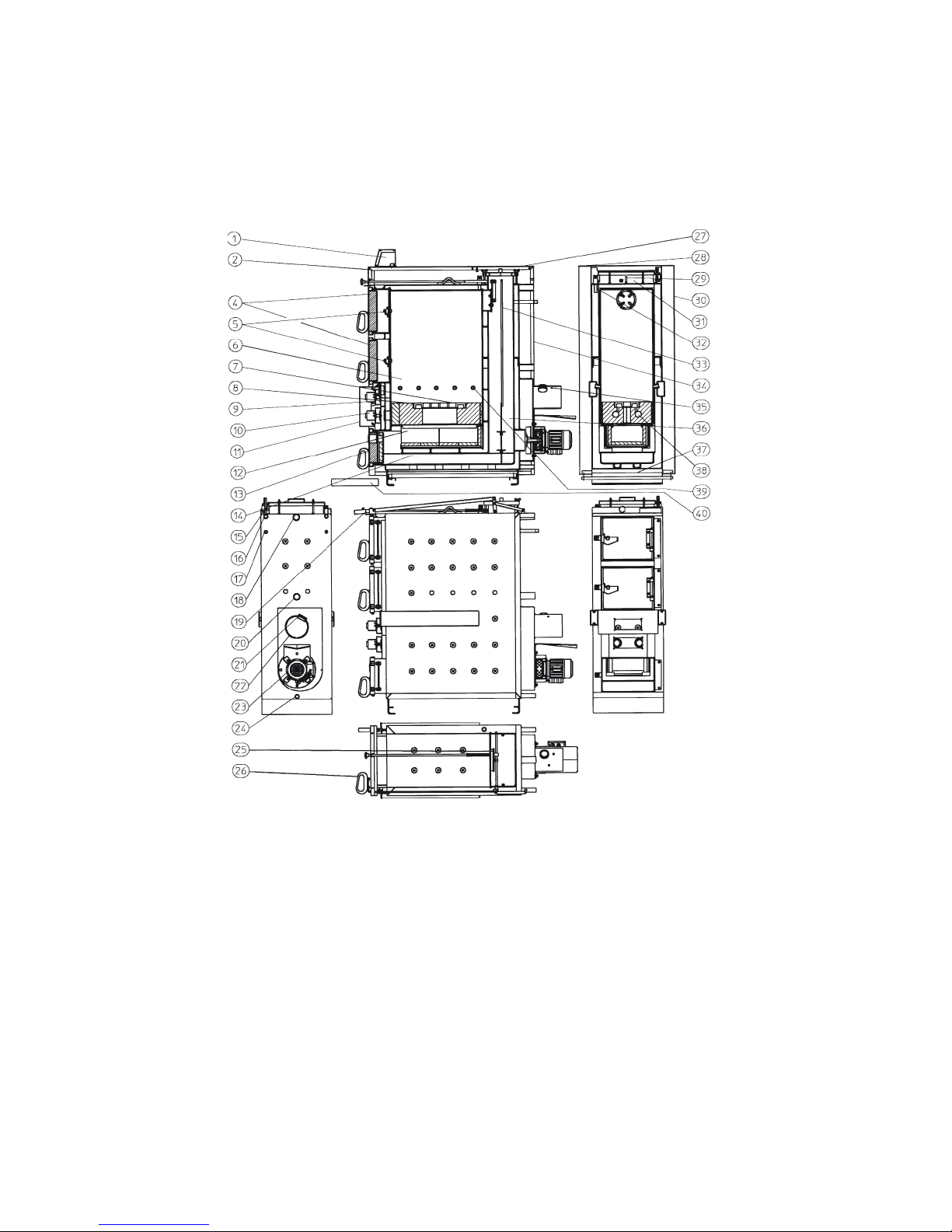
Overview
Boiler illustration
20 - 30, 40S, 50 - 70
1 Computer-controlled lambda
control
2 Cladding, front lid
4 Filling door (type 40S-70has two
filling doors)
5 Inner door
6 Filling chamber (fuel storage
chamber)
7 Burner grating
8 Burner brick
9 Primary air regulator unit with seal
10 Secondary air regulator unit with
seal
11 Cladding, actuator cover
12 Flame duct
13 Ashes door with sight glass
14 Ashes chamber
15 Cleaning lid
16 2 sleeves 1/2”
17 Heat exchanger connection R1/2”
for thermal discharge safety device
18 Heating feed connection
19 Opening rod for the gas vent flap
20 Heating return connection
21 Sleeve for O2 probe
22 Exhaust fume nozzle
23 Induced draft fan
24 Filling and emptying sleeve 1/2"
25 Gas vent flap
26 Opening handle for the gas vent
flap
27 Cladding, rear lid
28 Cladding, left side, with plug-in
wiring
29 Transport eye bolt
30 Cladding, right side
31 Insulating panel, top
32 Immersion sleeve for STL and
boiler temperature sensor
33 Exhaust fume baffle plate
34 Cladding, rear side
35 Thread for exhaust fume
sensor
36 Ancillary heating surface
37 Cladding, base
38 Secondary air apertures
39 Primary air apertures
40 Drip tray
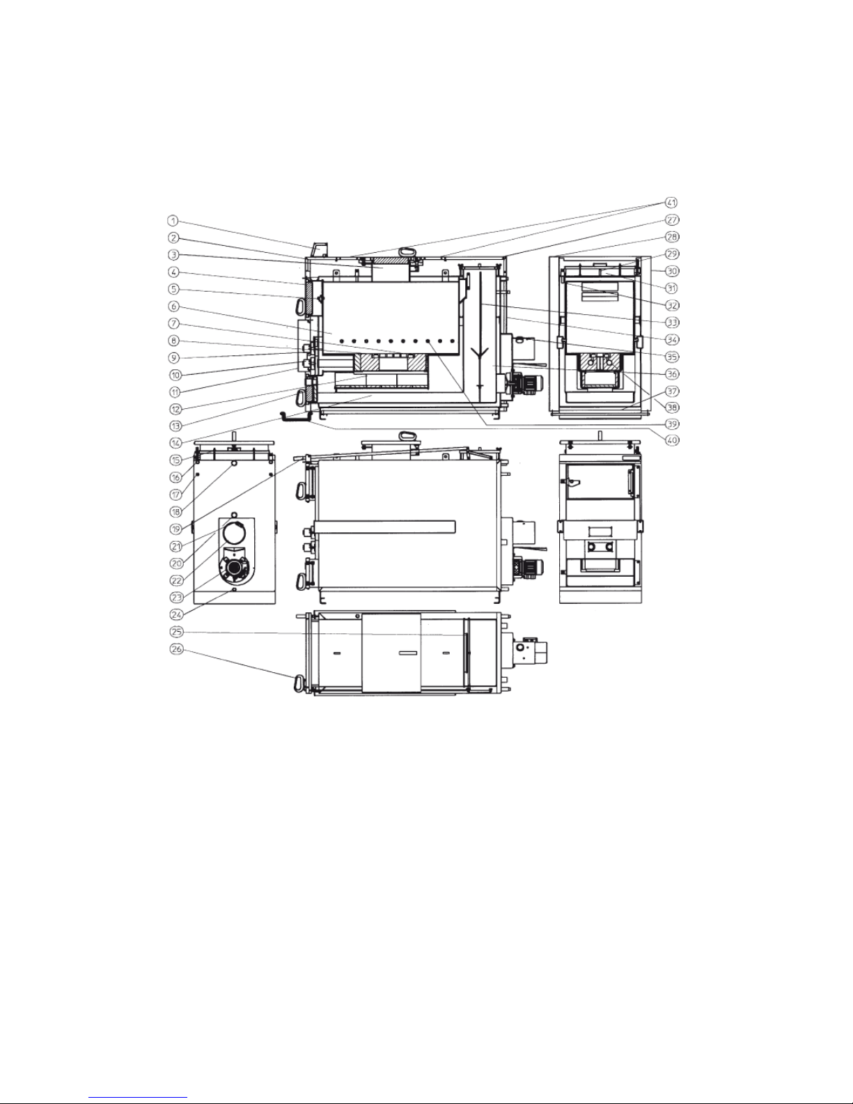
5
Overview
Boiler illustration
50L - 100L (Top loading door optional)
1 Computer-controlled lambda
control
2 Cladding, front lid
3 Filling lid
4 Filling door
5 Inner door
6 Filling chamber (fuel storage
chamber)
7 Burner grating
8 Burner brick
9 Primary air regulator unit with
seal
10 Secondary air regulator unit with
seal
11 Cladding, actuator cover
12 Flame duct
13 Ashes door with sight glass
14 Ashes chamber
15 Cleaning lid
16 2 sleeves 1/2”
17 Heat exchanger connection R1/2”
for thermal discharge safety
device
18 Heating feed connection
19 Opening rod for the gas vent flap
20 Heating return connection
21 Sleeve for O2 probe
22 Exhaust fume nozzle
23 Induced draft fan
24 Filling and emptying sleeve 1/2"
25 Gas vent flap
26 Opening handle for the gas vent
flap
27 Cladding, rear lid
28 Cladding, left side, with plug-in
wiring
29 Transport eye bolt
30 Cladding, right side
31 Insulating panel, top
32 Immersion sleeve for STL and
boiler temperature sensor
33 Exhaust fume baffle plate
34 Cladding, rear side
35 Thread for exhaust fume sensor
36 Ancillary heating surface
37 Cladding, base
38 Secondary air apertures
39 Primary air apertures
40 Drip tray
41 Optional Top loading door for
50L, 60L & 75L

6
Overview
Boiler technical data
Boiler
20
25
30
40
40S
50
60
70
50L
60L
75L
100L
Filling doors H/W
(2x for 40S-70)
cm
60/34
60/34
60/34
36/54
36/54
36/54
36/54
36/54
36/54
36/54
36/54
36/54
Flow /return
F/R
1¼’’
1¼’’
1¼’’
1¼’’
1¼’’
1¼’’
1¼’’
1¼’’
1¼’’
1¼’’
1½‘’
1½’’
Drain D 1/2"
1/2"
1/2"
1/2"
1/2"
1/2"
1/2"
1/2"
1/2"
1/2"
3/4
3/4
Safety heat
exchanger
HE
1/2"
1/2"
1/2"
1/2"
1/2"
1/2"
1/2"
1/2"
1/2"
1/2"
1/2"
1/2"
Opt. Filling lid
height/width
cm – –
– – – – – – 36/54
36/54
36/54
–
Weight
kg
515
515
515
710
925
925
925
925
940
940
1080
1200
Transport width
cm
50
50
50
69
69
69
69
69
69
69
69
89
General
operatin
g data
Rated heating power
kW
20
25
30
40
40
50
60
70
50
60
75
93
Max. operating
overpressure
bar 3 3 3 3 3 3 3 3 3 3 3 3
Permissible feed
temperature
°C
100
100
100
100
100
100
100
100
100
100
100
100
Min. return temperature
°C
55
55
55
55
55
55
55
55
55
55
55
55
Qmin. (SWT)
ltr/h
600
600
600
1000 1200
1200
1200
1200
1200
1200
1200
1400
Δp (20K)
mbar
0.57
0.89
1.3
2.3
2.3
3.6
5.2
7.1
3.6
5.2
5.2
6.6
Power
and
emission
data
at tested
rated
power
Exhaust fume
temperature
°C
158
160
163
169
169
173
178
182
173
172
171
169
CO2 content
%
15
15
15
15
15
15
15
16
16
16
15
15
CO (at 13% O2)
mg/Nm3
80
91
102
123
123
144
166
187
126
135
149
172
Solids emission (dust)
mg/Nm3
15
15
14
14
14
14
15
15
14
14
14
14
Boiler efficiency
%
91
90.8
90.6
90.1
90.1
90.3
90.4
90.6
90
90.4
91
91.9
Contents
Boiler water capacity
litres
115
115
115
210
255
255
255
255
370
370
410
470
Filling chamber volume
litres
150
150
150
190
290
290
290
290
340
340
400
460
Filling chamber depth
cm
60
60
60
60
60
60
60
60
110
110
130
110
Combustion duration
approx.
hrs.
7 6 5 5 8 7 6 5 8 6 6
6
Storage
tank
volume
Minimum Volume
Recommended by Strebel
litres
1200
1500
1800
2400
2400
3000
3600
4200
3000
3600
5000
8000
Flue
Required outlet pressure
mbar
0,10
0,10
0,10
0,10
0,10
0,10
0,10
0,10
0,10
0,10
0,10
0,10
Exhaust fume mass flow
rate
g/s
15
19
23
30
30
39
46
54
39
45
45
80
Diameter of exhaust
nozzle
cm
15
15
15
18
18
18
18
18
18
18
20
20
The manufacturer’s tables are authoritative for the dimensioning of the flue etc. Austria/Germany: in the case of existing systems, the flue must
be inspected by a master chimney sweep! UK & Eire: the chimney must be swept as per local regulations.
Strebelwerk GMBH reserve the right to change any data without prior notice.
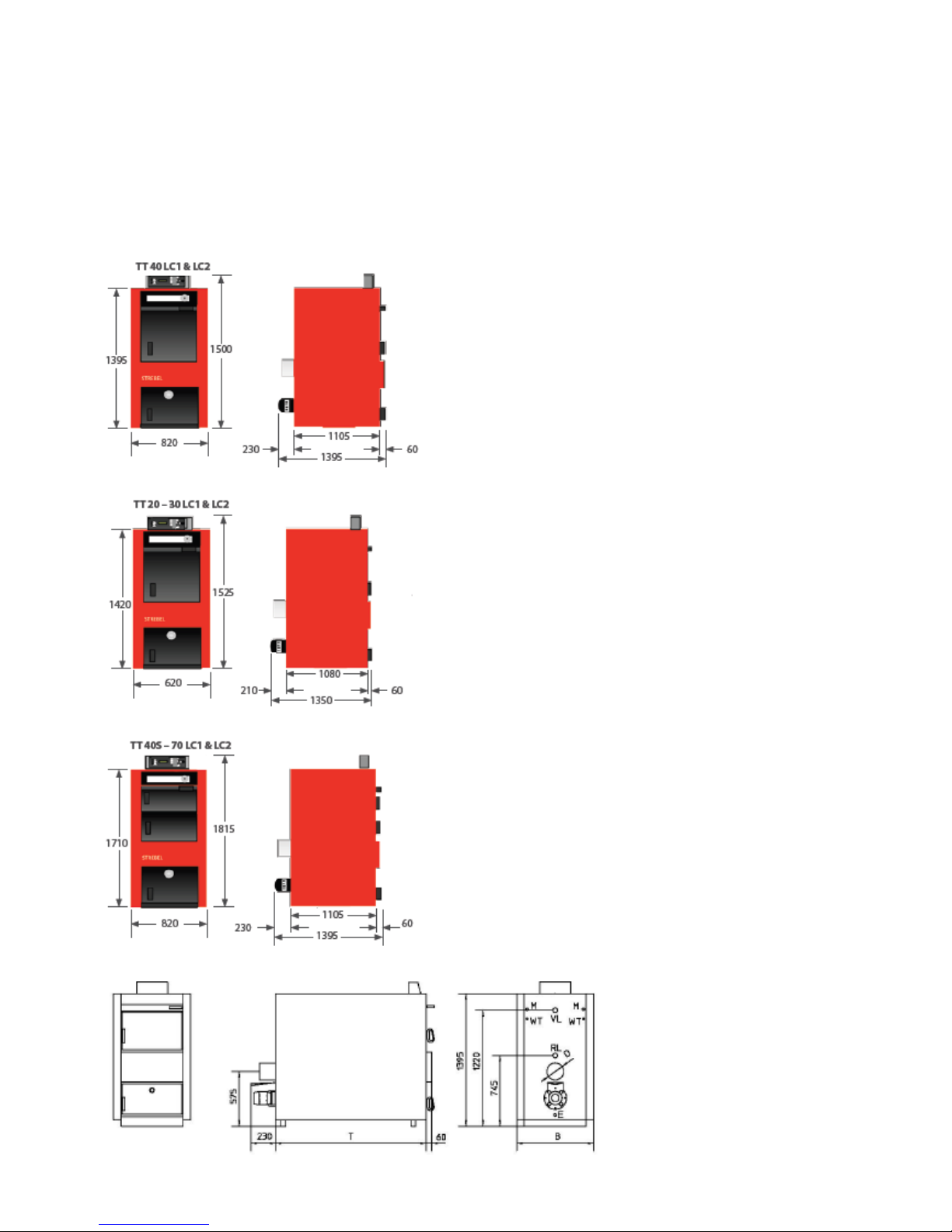
7
Overview
Boiler dimensions
Turbotec 40 lambda control
Turbotec 20 – 30 lambda control
Turbotec 40S – 70 lambda control
Turbotec 50L – 100L lambda control (Showing optional filling lid centre line)
8
Overview
Control technical data
Mains power supply
230V +10/-15% / 50Hz
Power consumption, electronics
max. 30VA at 230V
Maximum current consumption, entire system
Imax = 6.3 A
Fuse use
5 x 20 mm / 6.3 A quick-blow
Switch-off temperature of the safety temperature limiter
T = 100 C +0 / -5%
Heating circuit pump
Switching output: 230 V / max. 1.5 A
Charge pump for tap water storage tank
Switching output: 230 V / max. 1.5 A
Actuator drive for charge valve
Switching output: 230 V / max. 0.1 A
Induced draft fan
Switching output: 230 V / max. 1.5 A
Primary pump
Switching output: 230 V / max. 1.5 A
Actuator drive for return valve
Switching output: 230 V / max. 0.1 A
Floating switchover contact
Contact load: 230 V / max. 5 A
Control outputs for air regulator units
0 to 10 V / max. 3 mA
Power supply output for air regulator units
AC voltage output: 24 V / 6 VA
Electromagnetic door opener
AC voltage output: 12 V / 16 VA
Power supply output for O2 probe
AC voltage output: 12 V / 16 VA
Measurement input for Pt100 (R=108/20C)
- Storage tank sensor
- boiler sensor
- exhaust fume sensor
Maximum sensor temperature:
Tmax = 150C
Tmax = 150C
Tmax = 600C
Immersion sleeve for boiler sensor and safety temperature
limiter
2x LW7 with cable ties
Ms63, PN16, immersion depth 100
Protection class
IP 40 (appliance detached: IP 00)
Ambient operating temperature
0 C to +50 C
Ambient storage temperature
–20 C to +70 C
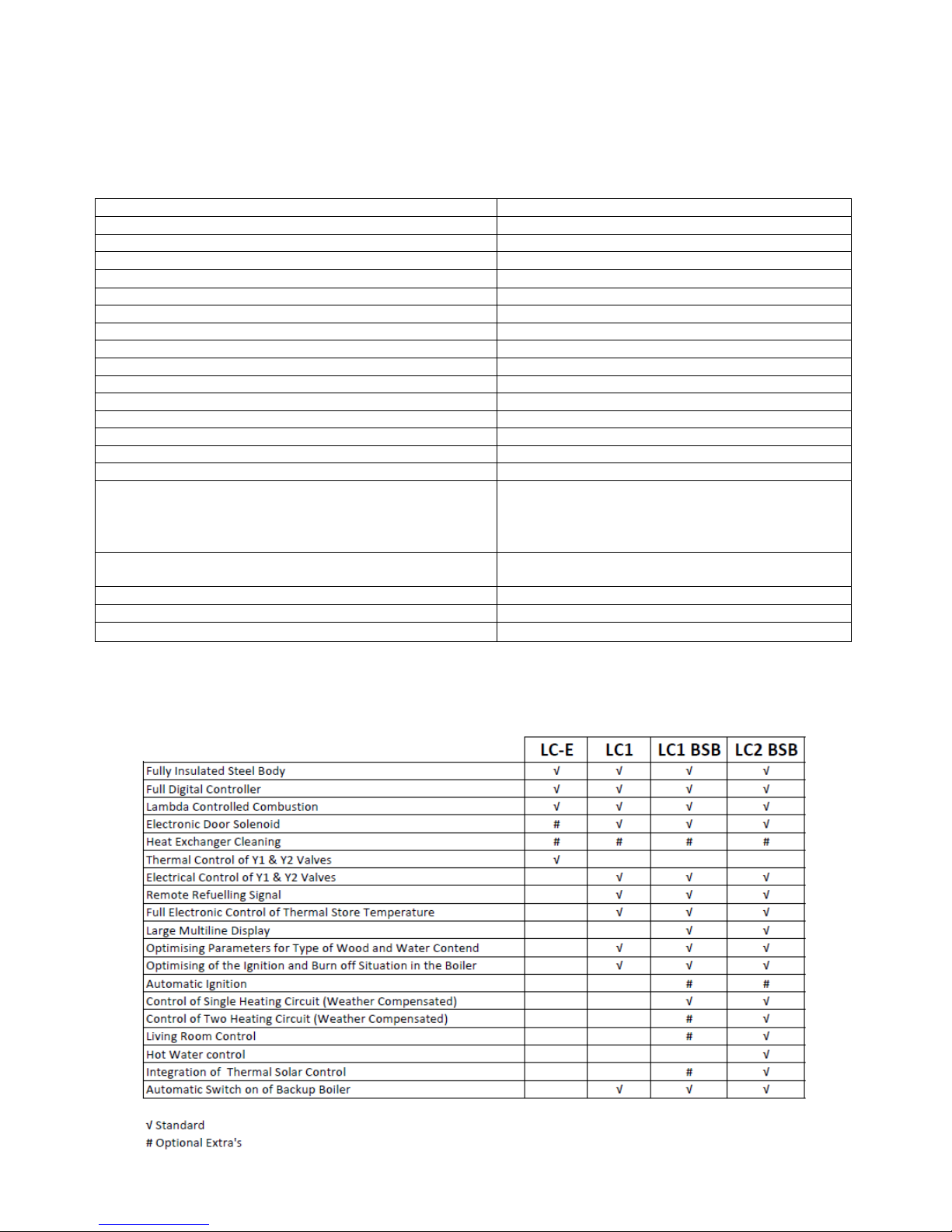
There are several controllers available in the Strebel Turbotec boiler range, each with their own special features. These controllers DO NOT
alter the performance of the appliance, only supplementing system/control outputs. Covered in this manual is LC1.

9
Overview
Boiler room/air supply/installation site
Checks following transport
Boiler room
With regard to the equipment in
the boiler room, the respective
local building regulations, the
applicable standards and fire
ordinances as well as fire
protection regulations are
authoritative. The installation
room must be frost-proof and
well ventilated. Any damage to
the boiler which occurs if these
requirements are not met, will
not be covered by the warranty.
Air supply
It must be ensured that there is
an adequate supply of fresh air
to the boiler room, so that the
combustion air required for the
operation of the installed
burners, can be replaced and
the operating personnel are not
endangered by a lack of oxygen!
The supply air must not be
contaminated by aggressive
vapours (e.g. hairspray,
percholoroethylene, carbon
tetrachloride).
Installation site
The boiler must be installed
levelly on a fortified floor. A
plinth is not required. For
unhindered operation and
maintenance of the boiler unit, it
must be ensured that there is a
passage width of at least 80cm
(type 20-70) / 130cm (type L) in
front of and on at least one side
of the boiler, and at least 50 cm
behind the boiler.
On the top side of the boiler, at
the back, there is a cleaning
aperture.. Therefore, the ceiling
clearance must be at least 60 to
80cm. Do not lay any pipes in
the vicinity of the cleaning lid
(15)!
Checks following transport
Attention must be paid to the
following points after transport
into the boiler room and before
commencing assembly:
- position of the lining stones in
the flame duct (12)
- position of the insulating stones
in the ashes door (13)
- sealing integrity of the doors;
the doors are adjustable on both
the hinge and closure sides
- remove all components from
the filling chamber, check them
against the packing list and lay
them out ready for assembly.

10
Assembly
Assembly of the cladding with insulation
Assembly of the cladding with
insulation
- Place the rear side cladding
(34) over the exhaust fume
nozzle onto the boiler.
- Slide in the base cladding (37).
- Hook the side claddings (28,
30) into the slots in the base
cladding (37) with the weldedon bolts and fasten at the top,
but do not tighten yet.
- Release the cable loom with
the plug out of the left side
cladding (28) for attachment to
the control later.
- Connect the rear side cladding
(34) to the side claddings (28,
30) using spring steel clips and
self-tapping screws.
- Place the top insulating plate
(31) on top of the boiler.
- Hook in the front lid cladding
(2).
- Adjust the heights of the side
claddings (28, 30) using the
knurled nuts so that the front
edge of the side cladding (28,
30) aligns with the doors at the
front.
- Unhook the front lid cladding
(2), tighten the side claddings
(28, 30) at the top and bottom
and hook in the front lid
cladding again.
- Lay ready the actuator cover
cladding (11), the rear lid
cladding (27) and, in the case
of type L, the cover panels
(41).

11
Assembly
Flue / mounting the air regulation units
Mounting the induced draft fan
Electrical / Water connection / heating connections
Flue
The flue must be checked by the
responsible master chimney
sweep before the heating boiler
is installed. The suitability of the
flue must be confirmed, together
with the findings. A flue which
conforms to regulations and is
correctly dimensioned for the
boiler power according to DIN
4705, is a prerequisite for the
proper and economical operation
of the heating system (see
picture for a classic example).
The exhaust fume values are to
be taken from the ‘Boiler
technical data’ sheet. If neither a
high thermally insulated flue
(heat conductivity resistance
group I according to DIN 18160
T1), nor a building authority
approved exhaust fume system
is used, the minimum exhaust
fume temperature can be limited
to, or set at 160 C via the
control. The exhaust fume pipe
between the boiler and the flue
must be absolutely airtight and
insulated, since otherwise the
induced draft fan can blow
exhaust fumes and ashes into
the boiler room through leaks
when the flue is cold. To assist
with pressure fluctuations, it is
recommended to fit a draft
stabiliser.
Mounting the air regulation
units
Fasten the primary and
secondary air regulator units
including the seals provided, to
the boiler, as shown in the
diagram.
Connect the plugs to the
connector strip at the front and
hook in the actuator cover (11).
Caution: Never separate the
air regulator flap and the
actuator from each other!
Mounting the induced draft
fan
Fasten the induced draft fan to
the boiler using four nuts as
shown in the diagram and
connect the plug to the
connector strip at the rear.
Electrical connections
The installation of any electrical
services during the installation of
this boiler and the associated
heating system must be carried
out by a registered competent
electrician and in accordance
with the requirements of the
latest issue of BS 7671.
Water connections
Filling and draining
A 1/2" sleeve (24) is provided on
the rear side of the boiler for the
filling and draining cock.
Heating connections
Boilers from the Turbotec range
have the flow and return
connections (18, 20) on the rear
side of the boiler.
Caution: The O2 probe and the
exhaust temp sensor must be
installed in the exhaust pipe; it
is essential to keep this place
free from pipework!
The water system must be
suitably vented & inhibitor used
when filling and a double-feed
indirect cylinder to the current
issue of BS 1566, Copper
indirect cylinders for domestic
purposes, Part 1Specification
for double feed indirect
cylinders is necessary where
there is a combined hot water
and central heating system.
There is no requirement for a
gravity heat-leak radiator or towel
rail to dissipate heat when the
pump is off due to the buffer
vessel and boiler thermal loss
able to compensate this.

12
Assembly
Raising the return temperature
Thermal discharge safety device
Mounting the O2 probe and the exhaust fume sensor
Raising the return temperature
The installation of a hydraulic
unit is mandatory in boilers
from the Turbotec series, since
without a hydraulic unit the
regulatory behaviour of the boiler
does not proceed correctly in
combination with the lambda
control. In general, operating
temperatures which are too low
shorten the service life of a
boiler considerably. Especially in
the area of the water-cooled
ancillary heating surfaces, where
the exhaust fumes temperatures
are already relatively low, the
water vapour in the exhaust
fumes will condense if the
temperature falls below the dew
point. This condensate causes
corrosion, hence shortening the
service life of the boiler.
Corrosion due to the formation of
condensate is avoided in
Turbotec boilers by the following
measures:
- the feed temperature is
maintained at a high level by the
lambda control.
- The return temperature is
maintained above the dew point
by the mandatory hydraulic unit
(see hydraulic unit).
Thermal discharge safety
device
In heating systems according to
DIN 4751 sheet 2, solid fuels
may only be fired if the boilers
are equipped with a suitable
safety heat exchanger and a
type-tested ‘thermal discharge
safety device’. The two 1/2"
threaded nozzles (17) of the
safety heat exchanger are
located at the rear side of the
boiler and can be used optionally
as water inlet or water outlet.
The safety heat exchanger may
not be used under any
circumstances as an operational
water heater! The
‘thermomechanical valve’ must
be connected, non-isolatable, to
the water supply network,
observing the direction of flow.
The cold water preliminary
pressure must be at least 2 bar!
The response temperature of the
thermomechanical valve must
not exceed 100 °C. The safety
heat exchanger and the thermal
discharge safety device must be
serviced and checked annually
by an expert.
TV = thermomechanical valve
M = ½” sleeve for valve probe
D = drain
CW = cold water
It is essential to mount a funnel
and drain pipe for the ‘thermal
discharge safety device’ – no
water must be allowed to flow
onto mounted electrical devices!!
Mounting the O2 probe and the
exhaust fume sensor
- Mount the exhaust fume sensor
on the exhaust fume nozzle and
connect the plug to the
connector strip at the
appropriate position (see plug
designation number).
- Screw the protective tube with
the pre-mounted O2 probe into
the sleeve (21) on the exhaust
fume nozzle (the thread of the
protective tube is already
wrapped with Teflon tape) and
connect the plug to the
connector strip at the
appropriate position (see plug
designation number).
13

Assembly
Mounting the storage tank sensor
Mounting the hydraulic unit
Mounting the control
Mounting the storage tank
sensor
- Insert the storage tank sensor
into the immersion sleeve on the
storage tank and connect the
plug to the connector strip at the
appropriate position (see plug
designation number).
Mounting the hydraulic unit
In order to raise the return
temperature and to ensure the
proper regulatory behaviour of
the boiler, it is mandatory to
install the following hydraulic
unit.
The hydraulic unit should be
installed to the left or right
coming from the boiler or
immediately after the boiler in
the heating feed pipe.
The following guide values must
be maintained when setting the
3-stage rotational speed switch
on the pump:
Boiler
Wilo Pump
Rotational
speed
stage
20
PICO30/1-6
1
25
PICO30/1-6
2
30
PICO30/1-6
3
40
PICO30/1-6
3
40S
PARA30/1-7
1
50
PARA30/1-7
1
60
PARA30/1-7
2
70
PARA30/1-7
3
50L
PARA30/1-7
2
60L
PARA30/1-7
2
75L
PARA30/1-8
2
100L
PARA30/1-8
3
In all cases the rotational speed
switch should be set in such a
way that a temperature
difference of 10 – 15 °C is
achieved between the boiler
feed and return.
The actuator on the 3-way valve
has an electrical end position
power-off switch and can
become defective if operated
manually.
Mounting the control
- Lay the lid cladding (2) on the
boiler and support it on the right
side cladding.
- Unpack the control,carefully,
unroll the capillary tube of the
safety temperature limiter (don’t
bend it!) and push it through the
recess in the lid.
- Insert the sensor of the safety
temperature limiter and the
boiler sensor into the boiler
immersion sleeve. The sensors
must be secured using the cable
ties provided in order to prevent
them being accidentally pulled
out.
- Thread the pre-wired terminal
strip from below through the
recess in the lid (2) and plug it
into the control in the correct
position (see label on the
control).
- Connect the protective earth
cable to the boiler lid using the
spade connector. Check that
the boiler protective earth
cable is connected correctly!
- Connect the plug for the mains
connection and boiler protective
earth cable.
Check that the boiler
protective earth cable is
connected correctly!
- Mount the control on the lid (2)
using the four screws provided.
- Hook in the cover plates (41) if
the boiler is a type L.
- Hook in the lid cladding (2) and
additionally the rear lid cladding
(27).

14
Assembly
Hydraulic diagrams
Overview
The following possibilities to
configure the system are stored
in the LC1 Control. Systems 3
and 3.1 are described in detail in
this installation manual.
If you wish to use a different
hydraulic system and you do not
yet have the corresponding
documents, we kindly ask you to
request them by contacting
Strebel. If an LC-E or BSB
controller is used; see separate
controller manual.
Overview of systems 1 to 5
System 1:
Monovalent system with or
without tap water storage tank
Control of tap water temperature
Manual or automatic heating
regulation with minimum heat
consumption
Heating release
Winter or summer function
selectable by customer
System 2:
Bivalent system with or without
tap water storage tank
Control of the tap water
temperature by the lambda
control or the control of the oil or
gas boiler
Heating regulation of the oil or
gas boiler with minimum heat
consumption
Forced heat consumption before
the boiler switches to standby
Automatic continuation of
operation in the case of an
alternative operating mode
Systems 3 and 4:
Monovalent or bivalent system
with buffer storage tank and
charging valve
Dimensioning of the boiler power
according to the calculated
heating needs
Heating priority (startup relief by
means of bypassing the buffer)
Intelligent buffer storage tank
management (buffer charging
priority depends on set boiler
temperature)
Residual heat withdrawal down
to minimum boiler temperature
(differential control)
Signal to add fuel if the storage
tank temperature falls below the
minimum
System 5:
Monovalent or bivalent system
with buffer storage tank
(charging valve optional)
Constant temperature control
through controlled return
temperature of the solid fuel
boiler
Control of the return temperature
of an oil or gas-fired boiler in
bivalent systems with automatic
continuation of operation
All storage tank connection
variants
Residual heat withdrawal
through minimum boiler
temperature
Signal to add fuel if boiler burns
out (automatic continuation of
operation)
Additional function with charging
valve
Dimensioning of the boiler power
according to the calculated
heating needs
Heating priority (startup relief by
means of bypassing the buffer)
Intelligent buffer storage tank
management (buffer charging
priority depends on set boiler
temperature)

15
Assembly
Hydraulic diagram – system 3
Electrical connection diagram
System no. 3, which is stored in the control, must be entered for the application cases defined in this installation manual.
Key
1 Turbotec wood gas boiler
2 Load compensation storage
tank, buffer storage tank or
energy storage tank
3 Heating distributor
4 Tap water storage tank
5 Heating circuit and tap water
control
6 Hydraulic unit
Y1 Return valve with actuator
Y2 Charging valve with actuator
Y3 Four-way valve with actuator
Y4 Non-return valve or flap
Z5 Non-return valve or flap
SS Storage tank sensor
(lambda control)
BS Boiler sensor for the heating
circuit and tap water control
P1 Primary pump
P2 Heating circuit pump
P3 Charging pump, tap water
storage tank
H1 Remote indicator ‘Add fuel’
Position Y2:
Storage tank bypassed (0)
Storage tank switched in (1)
Important instruction:
Stop valves, vents and technical safety measures are not shown in this block diagram. These must be installed
system-specifically in accordance with standards and regulations.
The electrical installation of the boiler system, including all control and safety devices, may only be performed by a
qualified electrician. The relevant national regulations (Germany: VDE DIN 57116 Electrical Equipment of
Combustion Plants; Austria: ÖVE 0116) and the Technical Connection Conditions) of the electricity supply
company must be complied with.

System 3
16
Assembly
System 3
Functional description
Important information
System 3
Turbotec wood gas boiler with
load compensation, buffer or
energy storage tank, tap water
storage tank, weather guided
heating circuit and tap water
control.
Functional description
System 3
If the heating is switched on on
the Turbotec,
- the remote indicator H1 goes
out.
- If the boiler temperature
reaches 50 C, the primary
pump P1 switches on and the
return temperature of the
Turbotec is raised via the return
valve Y1.
- From a boiler temperature of
55 C, the return valve Y1 opens
(the return temperature
continues to be raised) and heat
is discharged to the upper part of
the load compensation, buffer or
energy storage tank.
- Once the minimum
temperature has been reached
at the boiler sensor BS of the
heating circuit and tap water
control system, the charging of
the tap water storage tank takes
place according to the program
and heat is discharged to the
heating system.
- From a boiler temperature of
72 C, and depending on the
heat consumption and the target
boiler temperature that has been
set, the load compensation,
buffer or energy storage tank is
switched in and charged
accordingly.
- If the fuel is exhausted, the
heating is switched off. The
residual heat from the boiler is
fed into the load compensation,
buffer or energy storage tank
depending on the temperature
difference (between the boiler
temperature and the storage
tank temperature). Once the
boiler temperature has fallen
below the minimum value Tkmin
(can be set in the installer
menu), the withdrawal of heat
from the boiler is ended.
- The stored heat can now be
discharged to the heating
system or the tap water storage
tank, as required.
- Once the temperature in the
load compensation, buffer or
energy storage tank falls below
the minimum value TSmin (can
be set in the installer menu), the
remote indicator H1 lights up.
- Once the temperature at the
boiler sensor BS of the heating
circuit and tap water control
system falls below the minimum
value, the discharge of heat to
the heating system or tap water
storage tank is ended.
Important instruction:
The setting of a boiler
temperature TK S of 85 C
causes the load
compensation, buffer or
energy storage tank to be
charged at the same time as
heat is discharged to the
heating system.
The storage charging valve Y2
begins to open from a boiler
temperature TK I of 72 °C. In
other words, the boiler output is
only reduced after the load
compensation, buffer or energy
storage tank has been charged.
The setting of a boiler
temperature TK S of 70 C
causes the load
compensation, buffer or
energy storage tank to be
charged only after the
produced boiler output is no
longer consumed by the
heating system. The boiler
temperature will therefore
continue to increase and the
storage charging valve Y2
begins to open from a boiler
temperature TK I of 72 °C. In
other words, the boiler output is
reduced before the load
compensation, buffer or energy
storage tank has been charged.

17
Key
1 Turbotec wood gas boiler
2 Load compensation storage
tank, buffer storage tank or
energy storage tank
3 Heating distributor
4 Tap water storage tank
5 Oil or gas-fired boiler
6 Hydraulic unit
Y1 Return valve with actuator
Y2 Charging valve with actuator
Y3 Four-way valve with actuator
Y4 Non-return valve or flap
Z5 Non-return valve or flap
SS Storage tank sensor
(lambda control)
P1 Primary pump
P2 Heating circuit pump
P3 Charging pump, tap water
storage tank
Position Y2:
Storage tank bypassed (0)
Storage tank switched in (1)
Important instruction:
Stop valves, vents and technical safety measures are not shown on this block diagram. These must be installed
system-specifically in accordance with standards and regulations. In the case of operation with one flue, an
approved exhaust fume temperature monitor (DIN 3440) must be fitted to the Turbotec and switches mounted on
the doors and in the control chain of the oil and gas-fired boiler.
The electrical installation of the boiler system, including all control and safety devices, may only be performed by a
qualified electrician. The relevant national regulations (Germany: VDE DIN 57116 Electrical Equipment of
Combustion Plants; Austria: ÖVE 0116) and the Technical Connection Conditions) of the electricity supply
company must be complied with.

System 3.1
18
Assembly
System 3.1
Functional description
Important information
System 3.1
Turbotec wood gas boiler with
load compensation, buffer or
energy storage tank, tap water
storage tank, oil or gas-fired
special boiler, weather guided
heating circuit and tap water
control system
Functional description
System 3.1
If the heating is switched on on
the Turbotec,
- the oil or gas-fired burner is
switched off. The functions of the
weather-guided heating circuit
and tap water control system are
retained.
- If the boiler temperature
reaches 50 °C, the primary
pump P1 switches on and the
return temperature of the
Turbotec is raised via the return
valve Y1.
- If the boiler temperature in the
Turbotec reaches 55 C, the
return valve Y1 opens (the return
temperature continues to be
raised) and, through the
weather-guided heating circuit
and tap water control system,
the heat is discharged to the
heating system resp. to the tap
water storage tank.
- From a boiler temperature of
72 °C, and depending on the
heat consumption and the target
boiler temperature which has
been set, the load
compensation, buffer or energy
storage tank is switched in and
charged accordingly.
- If the fuel is exhausted, the
heating is switched off. The
residual heat from the boiler is
fed into the load compensation,
buffer or energy storage tank
depending on the temperature
difference (between the boiler
temperature and the storage
tank temperature). Once the
boiler temperature has fallen
below the minimum value Tkmin
(can be set in the installer
menu), the withdrawal of heat
from the boiler is ended.
- The stored heat can now be
discharged to the heating
system or the tap water storage
tank, as required.
- Once the temperature in the
load compensation, buffer or
energy storage tank falls below
the minimum value TSmin (can
be set in the installer menu), the
oil or gas-fired burner is released
and can be put into operation,
depending on the weatherguided heating circuit and tap
water control system.
Important instruction:
The setting of a boiler
temperature TK S of 85 °C
causes the load
compensation, buffer or
energy storage tank to be
charged at the same time as
heat is discharged to the
heating system. The storage
charging valve Y2 begins to
open from a boiler temperature
TK I of 72 °C. In other words, the
boiler output is only reduced
after the load compensation,
buffer or energy storage tank
has been charged.
The setting of a boiler
temperature TK S of 70 °C
causes the load
compensation, buffer or
energy storage tank to be
charged only after the
produced boiler output is no
longer consumed by the
heating system. The boiler
temperature will therefore
continue to increase and the
storage charging valve Y2
begins to open from a boiler
temperature TK I of 72 °C. In
other words, the boiler output is
reduced before the load
compensation, buffer or energy
storage tank has been charged.
If both boilers are operated with
one chimney, an approved
exhaust fume temperature
monitor (DIN 3440) must be
fitted to the Turbotec in addition
to a switch on each door so that,
at an exhaust fume temperature
of 80 °C on the Turbotec or upon
the opening of one of its doors,
the oil/gas-fired boiler will be
switched off immediately.

19
Assembly
Settings for system 3
Settings for system 3
Once the electrical connection
for System 3 has been made
and the control has been
mounted, the main heating
switch on site can be switched
on. This activates the electricity
supply and the following appears
on the display:
Code input + ### <--
Pressing the ‘Plus’ button
causes the displayed code
number (random number) to be
incremented by 1 (installer
setting menu = code + 1).
The code number is confirmed
by pressing the ‘Arrow’ button,
one arrives in the installer setting
menu and the following appears
on the display:
Language + [D] <--
The desired language for the
text display is selected via the
‘Plus’ and ‘Minus’ buttons.
The entry is confirmed by
pressing the ‘Arrow’ button, one
arrives at the next setting and
the following appears on the
display:
Boiler type + Turbotec 20 <--
The corresponding boiler type is
selected via the ‘Plus’ and
‘Minus’ buttons.
The entry is confirmed by
pressing the ‘Arrow’ button, one
arrives at the next setting and
the following appears on the
display:
System + No.: 0 <--
The desired System 3 is
selected by pressing the ‘Plus’
button.
The entry is confirmed by
pressing the ‘Arrow’ button, one
arrives at the next setting and
the following appears on the
display:
Are you sure ?
NO – YES <--
The entry is confirmed by
pressing the ‘Arrow’ button, one
arrives at the next setting and
the following appears on the
display:
Storage tank sensor + YES <--
The ‘Plus’ or ‘Minus’ button is
pressed to select whether or not
a storage tank sensor is present.
The entry is confirmed by
pressing the ‘Arrow’ button, one
arrives at the next setting and
the following appears on the
display (only if a storage tank
sensor is present):
Storage tank sensor + length in m 8 <--
If the factory-specified length of
the storage tank sensor cable
has to be changed due to
structural reasons, the actual
cable length can be entered by
pressing the ‘Plus’ or ‘Minus’
button so that correctly
measured values will be
obtained (max. cable length 50
metres, cable cross-section 2 x
0.75 mm2).
The entry is confirmed by
pressing the ‘Arrow’ button, one
arrives at the next setting and
the following appears on the
display (only if a storage tank
sensor is present):
Storage tank min. + -
TSmin [C] 45 <--
The minimum temperature in the
load compensation, buffer or
energy storage tank is selected
by pressing the ‘Plus’ or ‘Minus’
button. If the temperature falls
below the set temperature, the
‘Add fuel’ indicator is activated
and, in the case of bivalent
operation, the oil or gas burner is
released for operation.
The entry is confirmed by
pressing the ‘Arrow’ button, one
arrives at the next setting and
the following appears on the
display:
Boiler min. + -
TKmin [C] 60 <--
The minimum boiler temperature
down to which residual heat is
withdrawn from the boiler, is
selected by pressing the ‘Plus’ or
‘Minus’ button.
The entry is confirmed by
pressing the ‘Arrow’ button, one
arrives at the next setting and
the following appears on the
display:
Exhaust fume temp. min. +
TAmin [C] 100 <--
The minimum exhaust fume
temperature required for the flue,
is set by pressing the ‘Plus’ or
‘Minus’ button (the flue
manufacturer or chimney
sweep’s specifications must be
observed).
The entry is confirmed by
pressing the ‘Arrow’ button, one
arrives at the next setting and
the following appears on the
display:
Return valve + [sec] 150 <--
The running time of the return
valve actuator is set by pressing
the ‘Plus’ or ‘Minus’ button.
The entry is confirmed by
pressing the ‘Arrow’ button, one
arrives at the next setting and
the following appears on the
display:
Charging valve + [sec] 150 <--
The running time of the charging
valve actuator is set by pressing
the ‘Plus’ or ‘Minus’ button.
The entry is confirmed by
pressing the ‘Arrow’ button.
All of the previously set
values are now stored in the
control.
The installer settings menu is
now abandoned.

20
Assembly
Table for noting system settings
Aggregate test
The control has now been set up
for the existing system and is
ready for operation. The set
values can be changed at any
time in the installer settings
menu.
The set values should be noted
in the following table so that they
are available if service is
required.
Table for noting system
settings
Customer name
Street
Town/postcode
Tel. no.
Language
Boiler type
System no.
Storage tank sensor
Storage tank sensor
length in [m]
Minimum storage
tank temp.
Tsmin [C]
Minimum boiler
temp.
TKmin [C]
Minimum exhaust
fume temp.
TAmin [C]
Return valve running
time [sec]
Charging valve
running time [sec]
Aggregate test
Only possible in the operating
mode 'Heating OFF'.
For safety reasons, the
aggregate test may only be
carried out when there is no fuel
in the boiler.
The following appears on the
text display:
Heating
OFF
The selection menu is entered
by pressing the 'Arrow' button
and the following appears on the
display:
S E L E C T I O N + INFORMATION <--
By pressing the ‘Plus’ button, the
menu item
S E L E C T I O N + SETTINGS <--
Is selected. The selection menu
is abandoned automatically if no
button is pressed for more than
30 seconds.
By further pressing of the ‘Plus’
button, the following appears on
the display
S E L E C T I O N + AGGREGATE TEST
<--
The test run is activated by
pressing the ‘Arrow’ button and
the function of the aggregates
can be tested.
The displayed function or
displayed unit is switched on by
pressing the ‘Plus’ button.
The displayed aggregate is
switched off by pressing the
‘Minus’ button.
One arrives at the next test
step by pressing the ‘Arrow’
button.
The test run can be ended
prematurely by pressing the
‘Plus’ and ‘Minus’ buttons
simultaneously.
The displays, functions and
aggregates to be tested can be
seen in the ‘Short operating
instructions for the lambda
control’.

21
Commissioning
Instruction/commissioning/handover
Commissioning the control
Setting the boiler temperature
Instruction/commissioning/
handover
Following completion of the
hydraulic and electrical installation,
the boiler must be commissioned by
a qualified specialist.
Ensure all parts are fitted in
accordance with these instructions.
On completion of the installation
allow a suitable period of time for
any fire cement and mortar to dry
out, before lighting the boiler. Once
the boiler is under fire check all
seals for soundness and check that
the flue is functioning correctly and
that all products of combustion are
vented safely to atmosphere via the
chimney terminal.
On completion of the installation and
commissioning ensure that the
operating instructions for the boiler
are left with the customer. Please
advise the customer on the correct
use of the appliance and warn them
to use only the recommended fuel
for the boiler.
Advise the user what to do should
smoke or fumes be emitted from the
stove.
As part of the handover to the
system user, a qualified specialist
must explain the functions and
operation of the boiler precisely
in accordance with the
installation and operating
manuals. The commissioning
protocol can be used as an aid.
Commissioning the control
After turning on the main heating
switch on site, the power supply
to the control is activated and a
self-test of the control is carried
out automatically.
After completion of the self-test
the control is ready for operation.
Alternately, the operating status
and the boiler temperature
appear on the display. In the
event a malfunction is displayed
after turning on the main heating
switch, this must be fixed. (For
precise information about this,
please refer to the
‘Troubleshooting’ section).
The main heating switch
should in principle remain
switched on, since otherwise
important monitoring and
protective functions cannot be
performed.
Following the combustion
sequence, the control switches
automatically to stand-by
(energy efficiency function)
Setting the boiler temperature
Following the first
commissioning of the control and
the ensuing system settings by a
professional, the following
message appears on the text
display:
Heating
OFF
The Selection menu is entered
by pressing the 'Arrow' button
and the following message
appears on the display:
S E L E C T I O N + INFORMATION <--
The menu item ‘SETTINGS’ is
selected by pressing the ‘Plus’
button. The following appears on
the text display:
S E L E C T I O N + SETTINGS <--
The selected menu item is
confirmed by pressing the
‘Arrow’ button. The following
appears on the text display:
Boiler set point + TK S [C] ## <--
The value can be changed by
pressing the 'Plus' or 'Minus'
button.
Setting range: 70 – 85 C
(See important instruction –
function description)
The changed value is saved by
pressing the ‘Arrow’ button.
By pressing the ‘Arrow’ button
once again, one will arrive via
the next menu again to the text
display:
Heating
OFF
Commissioning the boiler
Heating up
During the initial commissioning,
resp. after a long standstill, the
following should be observed:
A ‘cold’ flue has no, or too little
outlet pressure, so that in this
case the exhaust fumes are
poorly expelled. Heating up will
be facilitated if you heat up the
flue with paper through the
cleaning hatch.
The following order of events
must be adhered to when
heating up the boiler:
- press the ‘Add fuel’ button. The
following appears on the text
display:
DO NOT OPEN!
Please wait!
- the induced draft fan operates
at high speed and the ‘Add fuel’
indicator blinks
- the door opener is released
after 15 seconds and the
following appears on the text
display:
C A U T I O N
OPEN SLOWLY!
Filling door 1 (centre) can now
be opened.
Filling door 2 (top), the filling lid
(60 L) and the ashes door
remain closed!
- open the interior door using the
operating hook
- switch off the induced draft fan
by pressing the ‘Minus’ button,
place 2 to 3 small dry split logs
inside, cover with kindling wood,
place paper and cardboard on
top and ignite from above.
- switch on the induced draft fan
again by pressing the ‘Add fuel’
button; the ‘Add fuel’ indicator
blinks for 10 minutes
- close the interior door; the
filling door remains open

22
Commissioning
Commissioning the boiler
Heating up/adding fuel
- wait until the control switches
automatically to the operating
mode ‘Heating ON’; the following
appears in the text display:
Heating
ON
and the ‘Heating ON’ indicator
lights up.
- open the interior door
- place wood lengthwise inside
the boiler, the logs parallel to
each other (not crosswise or
diagonally)
- close the interior door and the
filling door
- If necessary, also place wood
inside through filling door 2 or
the filling lid (type 60 L). Press
the ‘Add fuel’ button, then after
15 seconds:
- open filling door 2 and the
interior door or the filling lid; the
boiler can be filled to the top with
wood
- close the interior door and
filling door 2 or the filling lid
When the fuel has been used
up, the control switches
automatically into the operating
mode ‘Heating OFF’ and the
‘Heating ON’ indicator goes out.
Adding fuel
As a matter of principle, more
fuel should be added only if the
fuel has been used up totally,
when heating is required and the
‘Add fuel’ indicator lights up.
- Pull and latch the operating
handle of the gas vent flap
- Press the ‘Add fuel’ button. The
text display shows:
DO NOT OPEN!
Please wait!
The induced draft fan operates
at high speed and the ‘Add fuel’
indicator blinks for 10 minutes
- The door opener is released
after 15 seconds and the text
display shows:
C A U T I O N
OPEN SLOWLY!
Filling door 1 (centre) can now
be opened.
Filling door 2 (top), the filling lid
and the ashes door remain
closed!
- Open the interior door using
the operating hook
- Stir the fire bed to avoid the
formation of voids
- Place wood lengthwise inside
the boiler, the logs parallel to
each other (not crosswise or
diagonally)
- Close the interior door and
filling door 1
- If necessary, also place wood
inside through filling door 2 or
the filling lid.
Press the ‘Add fuel’ button; open
filling door 2 and the interior door
or the filling lid after 15 seconds
- The boiler can be filled to the
top with wood
- Wait until the control switches
automatically to the operating
mode ‘Heating ON’; the text
display shows:
Heating
ON
and the ‘Heating ON’ indicator
lights up.
- Close the interior door and
filling door 2 or the filling lid
- Unlatch the operating handle
of the gas vent flap and close
the flap.

23
Commissioning
Circuit diagram

Deutsch
Englisch
KESSELFÜHLER
BOILER SENSOR
TÜRÖFFNER
DOOR OPENER
SCHUTZLEITER Kesselseitenwand
PROTECTIVE EARTH CABLE boiler side wall
SCHUTZLEITER Kesseldeckel
PROTECTIVE EARTH CABLE boiler lid
NETZ
MAINS
STECKER 1
PLUG 1
RK
NC
AK
NO
WK
COM
VERDRAHTUNG JE NACH SYSTEMANWENDUNG HYDRAULIKSYSTEME 1-3
WIRING DEPENDS ON SYSTEM APPLICATION –
HYDRAULIC SYSTEMS 1 - 3
SPEICHERFÜHLER
STORAGE TANK SENSOR
Wärmeeinnahme EIN
Heat absorption ON
STELLANTRIEB RÜCKLAUFVENTIL
RETURN VALVE ACTUATOR
Wärmeeinnahme AUS
Heat absorption OFF
PRIMÄRPUMPE
PRIMARY PUMP
Stufe 2
Stage 2
SAUGZUGVENTILATOR
INDUCED DRAFT FAN
ABGASFÜHLER
EXHAUST FUME SENSOR
Heizung
Heating
O2-SONDE
O2 PROBE
Sonde
Probe
STECKERLEISTE 1
CONNECTOR STRIP 1
PRIMÄRLUFTREGELEINHEIT
PRIMARY AIR REGULATOR UNIT
SEKUNDÄRLUFTREGELEINHEIT
SECONDARY AIR REGULATOR UNIT

24
Commissioning
Short operating instructions

Deutsch
English
Wärmeerzeugung AUS
Heating OFF
AUSWAHL
SELECTION
INFORMATIONEN
INFORMATION
ENDE
END
Regelprogramm
Control program
Winterbetrieb
Winter operation
Höchstwert
Highest value
Betriebsstunden
Operating hours
Bereitschaft
Standby
keine Störung
no malfunction
EINSTELLUNGEN
SETTINGS
SOMMERBETRIEB
SUMMER OPERATION
AGGREGATETEST
AGGREGATE TEST
Kesselsollwert
Boiler set value
Servicecode mit
Service code with
Test
Test
Sonde
Probe
Testende
End of test
Primärpumpe
Primary pump
Rücklaufventil
Return valve
Ventilator
Fan
Türöffner
Door opener
Primärmotor
Primary motor
Sekundärmotor
Secondary motor
Ladeventil
Charging valve
Heizkreispumpe
Heating circuit pump
Ladepumpe
Charging pump
Umschaltkontakt
Switchover contact
Beleuchtung
Lighting
LED Wärmeerz.
LED Heating ON
LED Nachlegen
LED Add fuel
LED Störung
LED Malfunction
CODE Eingabe
CODE input
Sprache
Language
Kesseltyp
Boiler type
System Nr.
System no.
Sind Sie sicher?
Are you sure?
NEIN
NO
JA
YES
Speicherfühler
Storage tank sensor
Länge in m
Length in m
Speichermax.
Storage tank max.
Speichermin.
Storage tank min.
Kesselmin.
Boiler min.
Abgastemp. min.
Exhaust fume temp. min.
Anzeige nur bei System 1
Display only for system 1
Anzeige nur bei System 1 und 2
Display only for systems 1 and 2


Deutsch
English
Wärmeerzeugung EIN
Heating ON
AUSWAHL
SELECTION
INFORMATIONEN
INFORMATION
ENDE
END
Regelprogramm
Control program
Winterbetrieb
Winter operation
Höchstwert
Highest value
Betriebsstunden
Operating hours
Bereitschaft
Standby
keine Störung
no malfunction
EINSTELLUNGEN
SETTINGS
SOMMERBETRIEB
SUMMER OPERATION
KAMINFEGERTEST
CHIMNEY SWEEP TEST
AGGREGATETEST
AGGREGATE TEST
Kesselsollwert
Boiler set value
Servicecode mit
Service code with
Nennleistung
Rated power
Teillast
Partial load
Sicherheitstest
Safety test
Test wird durchgeführt
Test is carried out
CODE Eingabe
CODE input
Anzeige nur bei System 1
Display only for system 1
Anzeige nur bei System 1 und 2
Display only for systems 1 and 2

26
Maintenance
Boiler maintenance
Troubleshooting
Maintenance
(Heating to ‘OFF’)
Door closure bolts
The door closure bolts must be
oiled regularly.
Sealing integrity of the doors
If smoke escapes through the
doors, this is due to poor sealing
caused by the sealing material
yielding. The doors are
adjustable on both the hinge and
the closure sides and the sealing
integrity can therefore be
restored.
Sealing integrity of the gas
venting flap
The gas venting flap must lay
tightly against the frame for
proper, low-emission operation.
Sealing integrity of the O2
probe
The screw fitting of the O2 probe
must be checked for tightness (if
necessary carefully retighten).
Safety devices
The reliability performance of the
safety devices must be checked
once a year by the heating
installer or by another authorised
person. The safety valve and the
thermal discharge safety device
must be checked. It is
recommended to take out a
service contract with a specialist
firm!
Troubleshooting
The control recognises
malfunctions automatically and
executes malfunction-related
alternative programs or safety
measures.
There are two malfunction
categories: the ‘malfunction’
indicator either lights up
continuously or it blinks.
‘Malfunction’ indicator lights
up continuously
In the case of the following
malfunctions, the continuation
resp. switching on of the heating
function is not possible and the
malfunction indicator is activated
automatically:
Safety temperature limiter has
tripped
STL tripped
Reset!
Cause: boiler temperature is too
high (no heat consumption,
power failure, pump or valve
defective). After the boiler
temperature has dropped to
approx. 80 C due to heat
consumption, the STL is reset by
pressing the restart switch, thus
automatically acknowledging the
malfunction.
Measured values of the
exhaust fume temperature are
incorrect
Exhaust fume
temperature
Measured values wrong
Causes: plug contacts, sensor
cable, control, exhaust fume
sensor. After rectification of the
malfunction it will be
acknowledged by pressing the
‘Arrow’ button.
Measured values of the boiler
temperature are incorrect
Boiler temperature
Measured values wrong
Causes: plug contact, sensor
cable, control,boiler temperature
sensor. After rectification of the
malfunction it will be
acknowledged by pressing the
‘Arrow’ button.
Loss of control data
Data loss
Control defective
Cause: data memory in the
control is defective. The control
must be repaired by the
manufacturer.
‘Malfunction’ indicator blinks
In the case of the following
malfunctions, the continuation
resp. the switching on of the
heating function respectively is
possible until the malfunction
has been rectified:
The malfunction message is
shown on the text display in the
operating mode ‘Heating OFF’
and after the ‘Arrow’ button is
pressed:
Measured oxygen values are
incorrect
Oxygen
Measured values wrong
Causes: plug contact, probe
cable, O2 probe dirty/worn or
screw fitting of the O2 probe and
protective tube is loose, control.
Check the O2 probe by means of
the aggregate test.
If the result of the aggregate test
is ‘Probe OK’, then the
malfunction is automatically
deleted.
Important instruction:
Only perform the aggregate test
if there is no fire or residual
embers in the boiler.

27
Maintenance
Troubleshooting
Measured values of the
storage tank temperature are
incorrect
Storage tank temp.
Measured values wrong
Causes: plug contact, sensor
cable, control, storage tank
temperature sensor.
After rectification of the
malfunction it must be
acknowledged by pressing the
‘Arrow’ button.
Boiler temperature too low
Boiler temperature
too low [C] ###
Causes: plug contact, cables,
non-return valve, actuator,
control.
After rectification of the
malfunction it must be
acknowledged by pressing the
‘Arrow’ button.
Exhaust fume temperature too
high
Exhaust fume
temperature
too high [C] ###
Cause: because of a too long
fuel adding procedure or open
gas vent flap, the exhaust fume
temperature has exceeded 300
C.
For rectification, refer to the
operating manual.
Work on the electrical
equipment may only be
carried out by a specialist
after disconnecting the
installation from the mains!

28
Notes

29
ATTENTION!
IMPORTANT WARRANTY
INSTRUCTION
Dear sir or madam,
We are delighted that you have chosen a Strebel Turbotec wood gas boiler.
This is a product of the highest quality, which stands out due to its numerous
features designed for your convenience and safety, its durability and its high
efficiency. A pioneer in wood gasification. In order to be able to use these
advantages to the fullest extent, a conscientious commissioning of the boiler and
comprehensive information about its operation are indispensable.
For this reason we have included with your boiler a commissioning protocol and
would ask that you return this to us, having been filled in fully by a professional,
after completion of the commissioning, but at the latest within two months after
delivery. The boiler warranty will not become effective until we have received the
completed protocol.
Please note: without this protocol, which confirms the proper handover and
training of the user, we cannot give any warranty! Please contact Strebel to
arrange commissioning or training by our own engineers, if required!
We would like to thank you very much for placing your trust in Strebel, you will get
many years of pleasure from your new boiler!
Strebel Ltd
Unit 1F Albany Park Industrial Estate, Frimley, Camberley Surrey GU16 7PB
Tel: 01276 685422
Fax: 01276 685405
Email: info@strebel.co.uk

COMMISSIONING PROTOCOL
CUSTOMER NAME
INSTALLER NAME
Street
Street
Town/postcode
Town/Postcode
Tel. no.
Tel. no.
Boiler type
Email
Serial no.
Engineer Name
Mrs/Ms/Mr
Controller (eg. LC1)
Date
Signature
Signature
HYDRAULIC AND SAFETY DEVICES
OK
REMARK
System assembled according to Strebel hydraulic diagrams
System no.: ……….
Boiler and system vented, system pressurised, stop valves open
Thermal discharge safety device connected (primary pressure 2 bar,
valve sealed)
3 bar pressure relief valve connected to boiler flow
Expansion vessel approx. (5) – 10 % of total water volume
FLUE
OK
REMARK
Flue diameter approx. equal to diameter of the exhaust fume nozzle,
otherwise increase TAmin by 20 °C/diameter step
Flue height ≤ 10 m, otherwise increase TAmin by 10 °C/m additonal flue
length. Please note cold chimney draught.
Flue exhaust fume path free, pipe connections sealed
No other fireplaces connected to the flue
No electrical cables or combustible parts in the exhaust fume pipe
BOILER
OK
REMARK
Oxygen probe mounted with seal and tightened
Air regulator units mounted tightly
STL sensor and boiler temperature sensor with contact spring inserted
fully into the boiler immersion sleeve
Cleaning lid and doors tightly sealed
Flame duct and ashes door linings OK
Cast grating placed in position
Drip tray removed from the boiler
ELECTRICAL CONNECTION
OK
REMARK
Voltage supply 230 V with protective earth cable
Electrical installation according to connection diagram
Protective earth cable connected to boiler lid via spade connector
Plugs latched in place at the rear side of the boiler and on the control
COMMISSIONING
Controller setting according to installation manual
OK
REMARK
Aggregate test carried out, whereby of particular importance are
Lambda probe
Return valve running direction
Primary motor running direction, end position
Secondary motor running direction, end position
Charging valve running direction
Test heating of boiler according to operating manual
OK
REMARK
Explanation of function and operation of the heating system
whereby of particular importance are
Cleaning the filling chamber floor
Cleaning the grating support and the secondary air zone

 Loading...