

Page 1
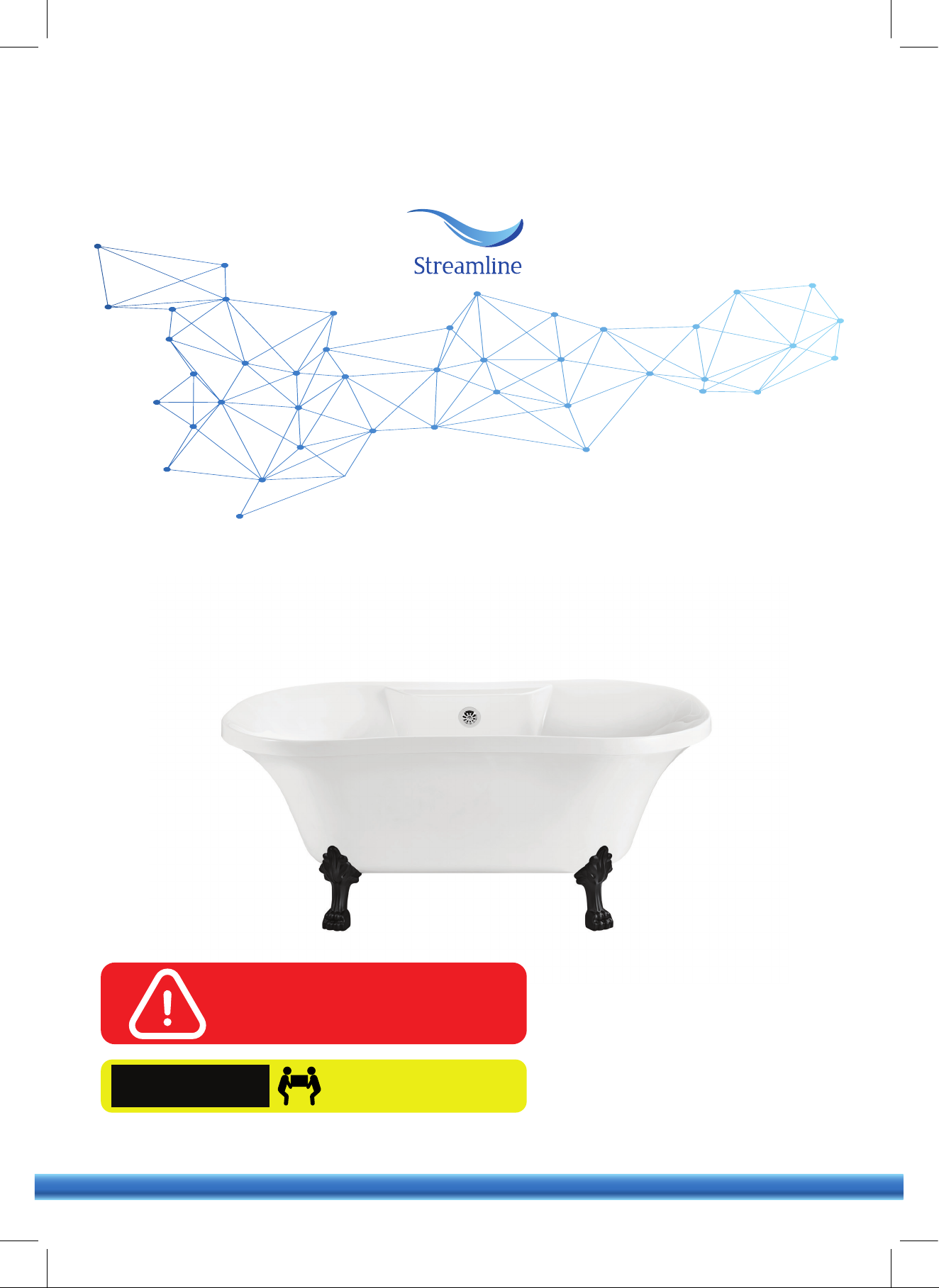
CLAWFOOT BATHTUB SERIES
OWNER'S MANUAL &
INSTALLATION GUIDE
READ ENTIRE INSTALLATION GUIDE
PRIOR TO INSTALLING THE BATHTUB
THIS BATHTUB SHOULD ONLY BE
INSTALLED BY A CERTIFIED PLUMBER
CAUTION!
QUESTIONS ON PRODUCT, INSTALLATION, RETURNS? PLEASE CONTACT
streamlinebath.com
TWO PEOPLE ARE REQUIRED
TO LIFT THE BATHTUB
(310) 935-0028[email protected]
Page 2
PRIOR TO INSTALLING
These products must be installed by a fully insured and licensed plumber only.
Installation of any product by anyone other than fully insured and licensed plumber shall void limited warranty.
We are not responsible for any local code compliance for this product.
Building and plumbing codes may vary state-to-state.
Streamline shall not be held liable for any and all incidental damages or flood caused due to use of this product.
Streamline shall not be held liable for any and all fees stemming from cost of installation, re-installation, removal,
subsequent damage, or transportation in a case of a product defect.
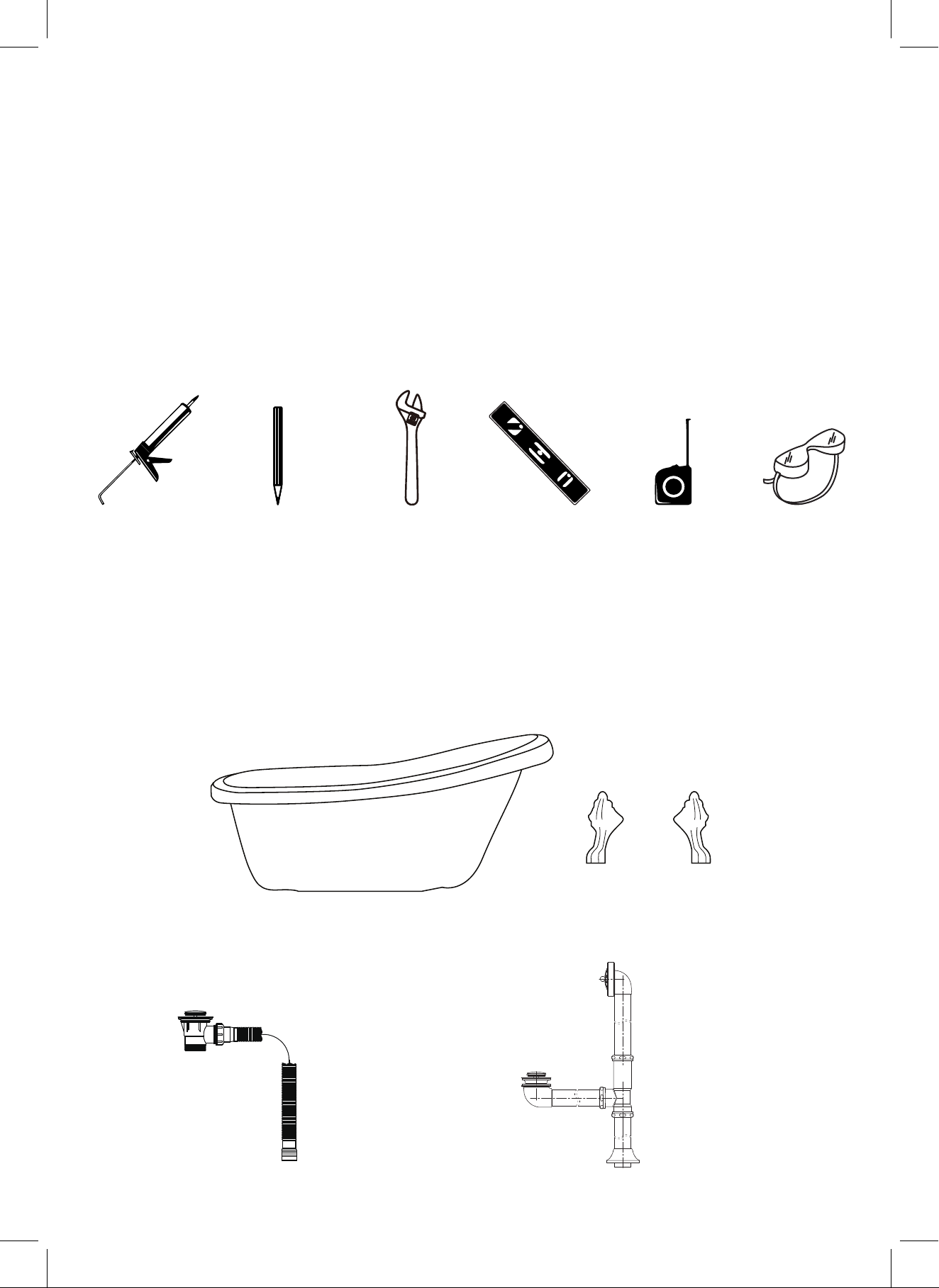
TOOLS REQUIRED
Silicone
Adjustable Key Measuring Tape Safety GlassesPencil Level Bar
WHAT'S IN THE BOX
Please note:
Different bathtub models have different drain & clawfeet models. Please see the next page to determine which
drain or clawfoot model applies to the bathtub model that you have purchased.
Bathtub
Clawfeet
(Pre-installed)
Model A1840-0
Model: N-DWF-GLD
Model: N-DWF-CH
DrainDrain
Page 3
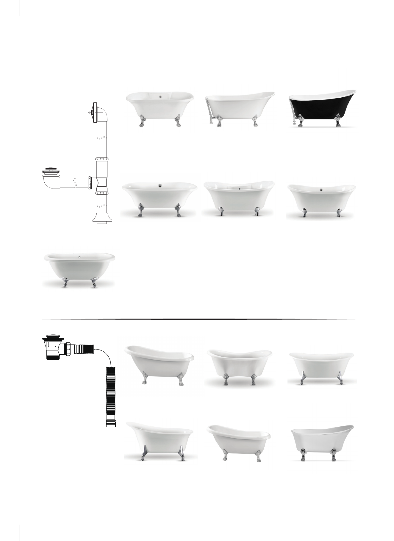
DRAIN MODEL COMPATIBILITY
FREESTANDING BATHTUB
N-DWF-CH
N-DWF-GLD
N-1120-59CFBL-DM
N-1121-67CFWH-DM
N-100-60CFWH-DM
N-101-68CFWH-DM
N-102-60CFRD-DM
N-103-68CFBL-DM
N-860-60CFGR-FM
N-861-68CFWH-FM
N-340-67CFWH-FM
N-341-59CFWH-FM
N-342-63CFWH-FM
N-343-55CFWH-FM
N-900-60CFWH-DM
N-901-68CFWH-DM
N-344-59CFBL-FM
N-345-67CFBL-FM
N-920-60CFWH-FM
N-921-68CFGR-FM
Model
Model A1840-0
N-480-61FSHW-FM
N-1100-59CFWH-FM
N-1101-67CFGR-FM
N-1020-62CFWH-FM
N-1021-62CFRD-FM
N-481-61FSBL-FM N-346-55CFWHIN-FM
N-482-61FSRD-FM
N-1080-59CFWH-FM
N-1081-67CFWH-FM
N-347-59CFWHIN-FM
N-348-63CFWHIN-FM
N-349-67CFWHIN-FM
Page 4
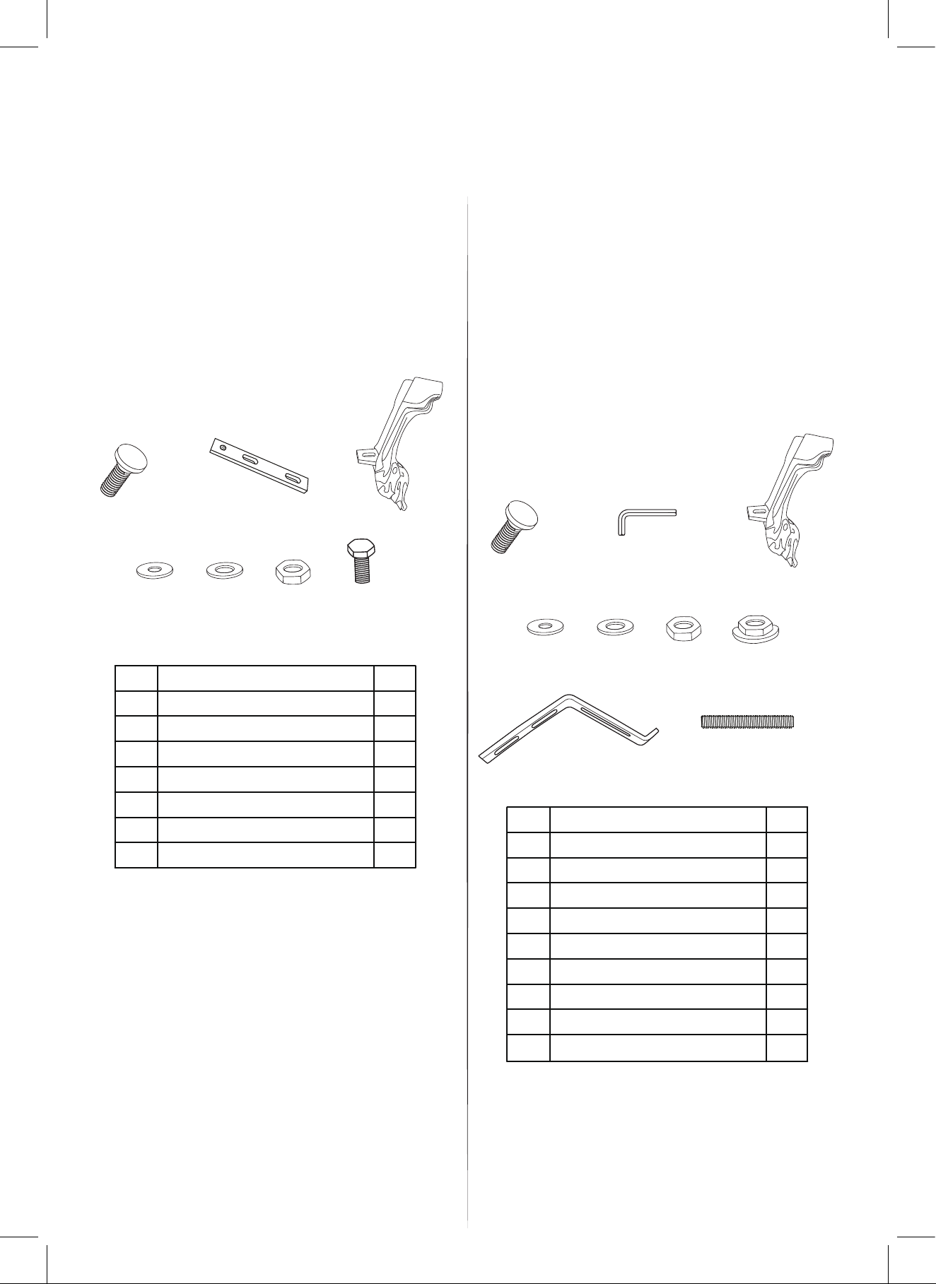
WHAT'S INCLUDED IN THE CLAWFOOT BOX
Applicable models :
N-CFL1775-CH N-CFL11603-BL
N-CFL1775-WH
N-CFL1775-BL
N-CFL1775-GLD
N-CFL1912-CH
N-CFL1912-WH
N-CFL1912-BL
N-CFL1912-GLD
N-CFL11603-CH
N-CFL11603-GLD
1
N-CFL11603-WH
N-CFLK36572-BL
N-CFLK36572-CH
N-CFLK36572-GLD
N-CFLK35672-WH
N-CFL46572-BL
N-CFL46572-WH
N-CFL46572-GLD
N-CFL46572-CH
2
Applicable models:
N-CFL11601-CH
N-CFL11601-WH
N-CFL11601-BL
N-CFL11601-GLD
3
1
2
3
4
Leveling Feet
1
2
Metal Plate
3
Claw Feet
4
Washer With Small Diameter
5
Washer With Large Diameter
Nut
6
7
Hex Bolt
5
ITEMNo.
6
7
Qty
4
4
4
8
4
8
4
4
Leveling Feet
1
2
Hex Key
3
Claw Feet
4
Washer With Small Diameter
5
Washer With Large Diameter
Nut
6
7
Nut With Washer
5
8 9
6
ITEMNo.
7
Qty
4
1
4
14
9
12
16
Metal Plate
8
9 8
Bolts
4
Page 5
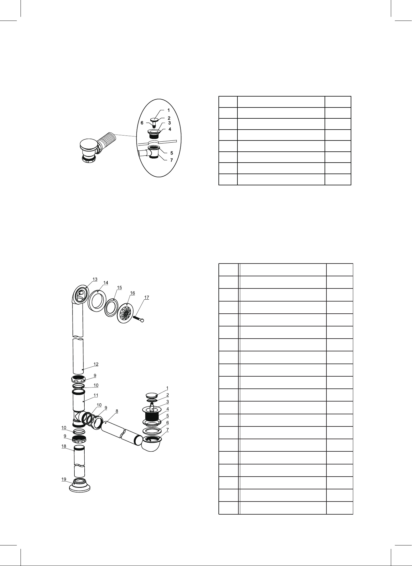
DRAIN DIAGRAMS
Model: A1840-0
ITEMNo.
Pop-Up Cover
1
O Ring
2
Strainer
3
Rubber Gasket
4
Flat Rubber Gasket
5
Cartridge
6
Tee
7
No ITEM Qty
Qty
1
1
1
1
1
1
1
1
Cover
2
Cover gasket
3
Cartridge
4
Strainer
5
Waste upper gasket
6
Waste lower gasket
7
Connector
8
Coupling nut
9
Nut
10
Washer
11
Tee
12
Pipe
13
Overflow body
14
Tapered rubber gasket
15
Overflow upper gasket
1
1
1
1
1
1
1
1
1
3
3
1
1
1
1
Model: N-DWF-GLD
Model: N-DWF-CH
16
Overflow plate
17
Pin Bolt
16
Taic piece
17
Flange
1
1
1
1
Page 6

CLAWFOOT DIRAGRAM
1
1
2
3
4
5
2
6
ITEMNo.
Leveling Foot
1
Nut
2
Clawfoot
3
4
Hex Bolt
Washer With Large Diameter
5
6
Washer With Small Diameter
7
Metal Plate
2
3
4
5
6
3
6
7
7
Qty
Leveling Foot
1
2
1
1
1
2
1
1
Metal Plate
2
Nut
3
4
Bolt
Washer With Small Diameter
5
6
Nut With Washer
Clawfoot
7
8
ITEMNo.
Qty
1
1
3
2
2
4
1
Washer With Large Diameter8 2
Applicable models :
CFL1775-CH N-CFL11603-BL
CFL1775-WH
CFL1775-BL
CFL1775-GLD
CFL1912-CH
CFL1912-WH
CFL1912-BL
CFL1912-GLD
N-CFL11603-CH
N-CFL11603-GLD
N-CFL11603-WH
N-CFLK36572-BL
N-CFLK36572-CH
N-CFLK36572-GLD
N-CFLK35672-WH
N-CFL46572-BL
N-CFL46572-WH
N-CFL46572-GLD
N-CFL46572-CH
Applicable models:
CFL11601-CH
CFL11601-WH
CFL11601-BL
CFL11601-GLD
Page 7
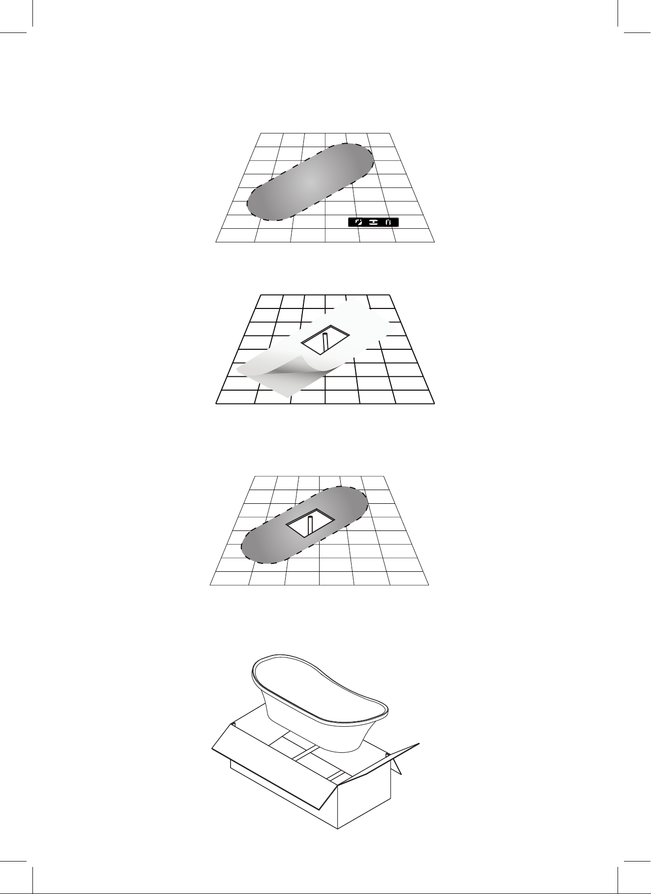
BATHTUB INSTALLATION
1. Ensure that the floor at the installation site has sufficient floor support and is level.
2. Waterproofing the floor is highly recommended.
3. Determine the location of the drainpipe on the floor by taking measurements of the drain and waste
location underneath the unit. Clean the drain hole area in preparation of setting the drain. The area
should be dry & free from any debris.
4. Remove the bathtub from its box. It is recommended that the bathtub is carried by a minimum of
two people. Ensure to carry and set down the bathtub only in the upside-down position.
Page 8
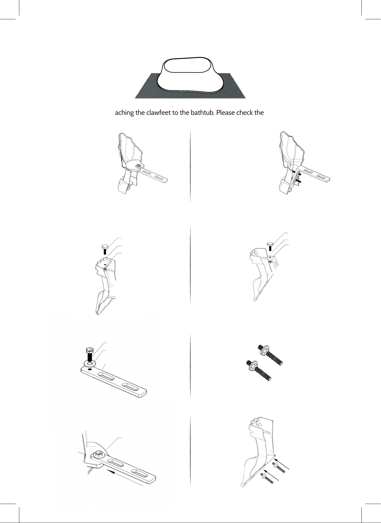
5. Gently place the bathtub in the upside-down position on a tarp or cardboard sheet in order to avoid
contact with any rough surface.
6. This step will be attaching the clawfeet to the bathtub. Please check the previous page to see which
clawfeet model is applicable to your bathtub.
Applicable models :
N-CFL1775-CH
N-CFL1775-WH
N-CFL1775-BL
N-CFL1775-GLD
N-CFL1912-CH
N-CFL1912-WH
N-CFL1912-BL
N-CFL1912-GLD
a) Take (1) adjustable foot [#1], place it through
the hole in the clawfoot [#3], and screw (1) nut [#2]
at the bottom of the adjustable foot.
1
2
3
a) Take (1) adjustable foot [#1] and put it through (1)
metal plate [#2], using (1) nut [#3] to tighten the
adjustable foot at the bottom.
Applicable models:
N-CFL11601-CH
N-CFL11601-WH
N-CFL11601-BL
N-CFL11601-GLD
1
2
3
b) Take (1) bolt [#4] and (1) washer [#5] and
place them through the metal plate [#8].
4
5
8
c) Take the metal plate and slip it snug with the
clawfoot [#3].
3
b) Take (1) bolt [#4] and (1) nut with washer [#6]
and screw the nut onto the bolt approximately 1/4
of the length of the bolt.
Repeat Step 1 with the second bolt.
c) Take the bolt & nut & screw them into the clawfoot
as shown in the diagram below. Make sure to tighten
the bolt into the clawfoot using the provided hex key.
Page 9
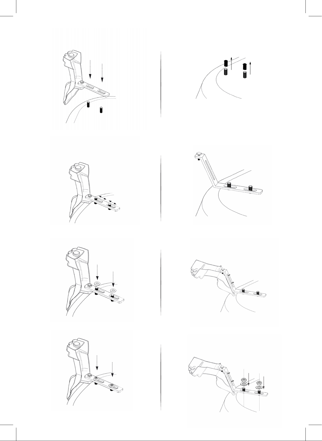
d) Place the metal plate on top of the bolts
that are already on the bottom of the bathtub.
e) Make sure to adjust the metal plate so that it fits
snug with the bolts on the bathtub. This will help to
ensure that the clawfeet are placed correctly and
are functioning properly.
d) Remove the safety caps from the bolts on the
bathtub.
e) Place the metal plate [#2] over the bolts on the
bathtub as shown in the diagram below. Make sure
to adjust the metal plate so that it fits snug with the
bolts on the bathtub. This will help to ensure that the
clawfeet are placed correctly and are functioning
properly.
f) Take (2) washers [#6] and place them over the
metal plates on the bathtub.
g) Put (1) nut [#2] over each of the metal bolts and
screw them on. Do not tighten yet.
f) Take the clawfoot [#7] & align it with the bathtub,
ensuring that the top top bolts go through the opening
and are fit snug with both the bathtub & metal plate.
g) Take (1) washer [#8] and put it over the bolt
on the bathtub. Then take (1) nut [#3] and place
it over the washer, but do not tighten the bolt
completely. Repeat this step for the other bolt
on the bathtub.
Page 10
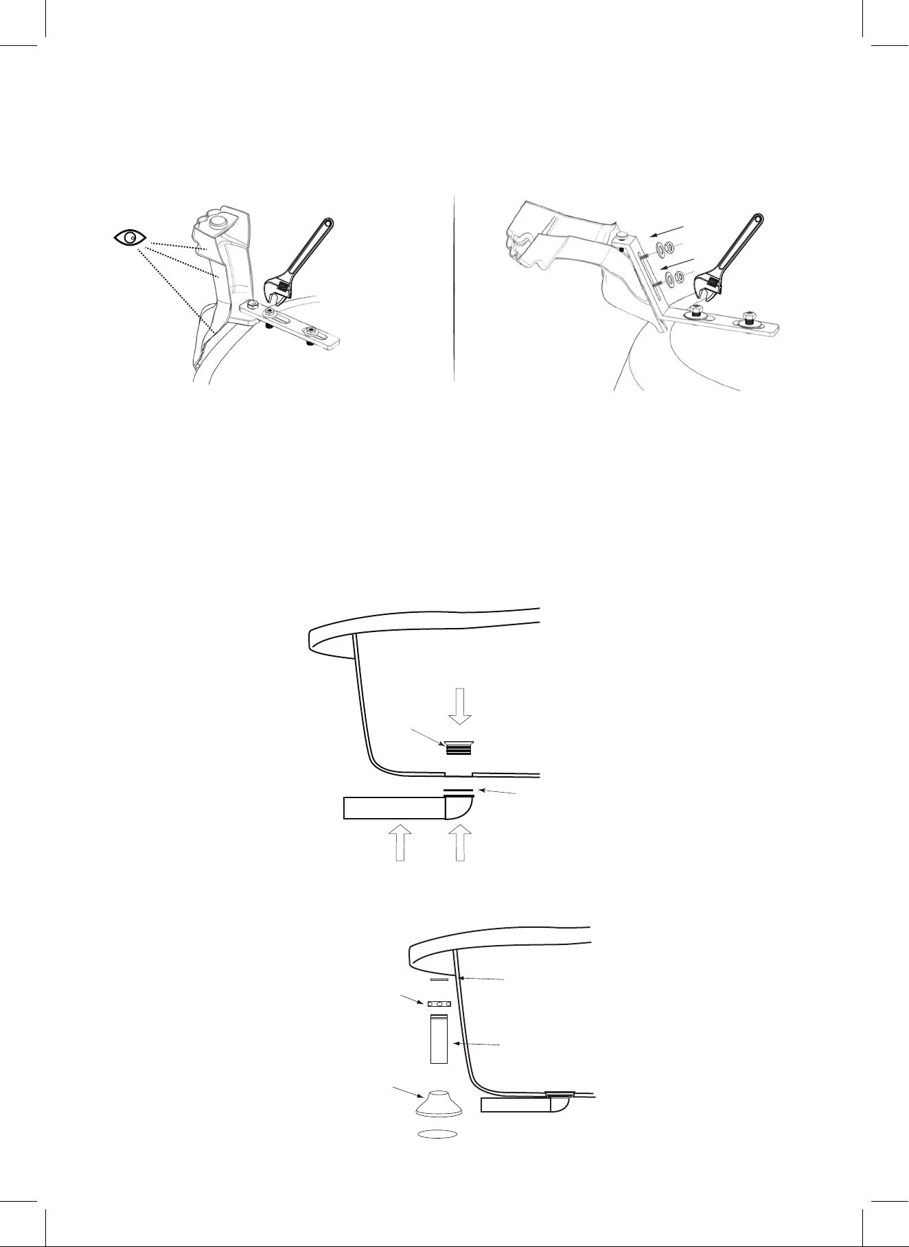
h) Check to ensure that the clawfoot is aligned
properly with the bathtub and is sitting snug
against the bathtub.
Once this is done, use a wrench to tighten all
of the nuts.
h) Take (1) washer [#5] and place it over the bolt
on the metal plate. Then take (1) nut with washer
[#6] and screw it into the bolt. Do not tighten.
Repeat the same step for the lower bolt. Once
this is done, use a wrench to tighten all of the nuts.
i) Repeat the same procedure for the other 3 legs. i) Repeat the same procedure for the other 3 legs.
The following drain installation is applicable to drain models N-DWF-CH & N-DWF-GLD. Please skip to
step 12 for drain model A-1840-0.
7. Take the strainer, place silicone sealant around it, and then place it into the drain hole ensuring
a tight connection with the drain ell & gasket. Use silicone sealant. DO NOT use plumbers putty to seal.
Silicone
Sealant
Strainer
Gasket
Drain Ell
8. Insert the tailpiece into the trap inlet using the O-ring, coupling nut, & flange. The tailpiece may
need to be cut for proper fit. 1''-2'' of the tail piece shoudl fit inside the trap. Slip the flange over the tailpiece
and slide down to the floor.
Coupling Nut
Flange
O Ring
Tailpiece
Trap Inlet
Page 11
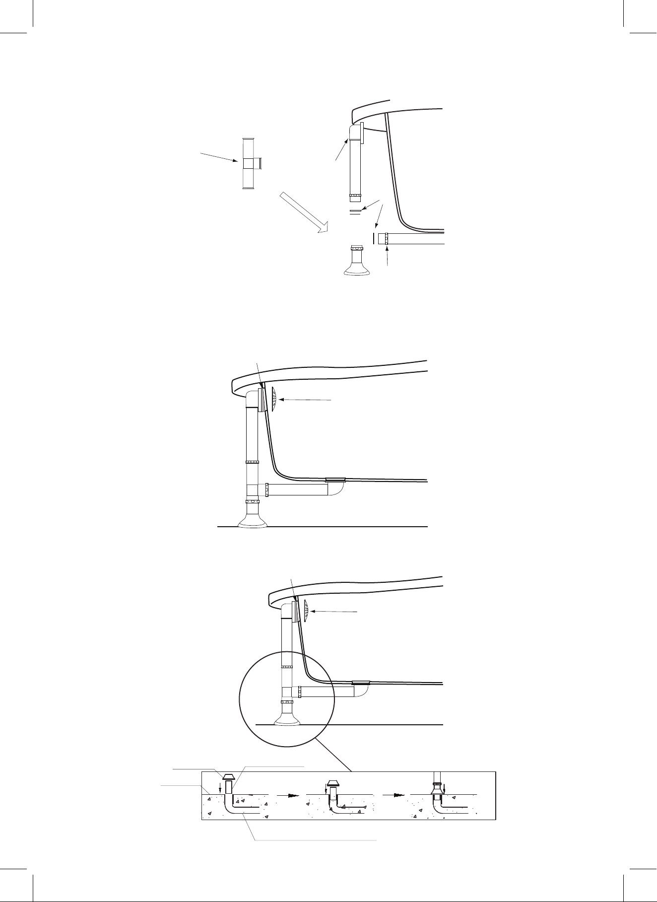
9. Assemble the tee section to the tailpiece, overflow, & drain ell using the coupling nuts and O-rings
that are provided.
Tee
Overow Ell
O Ring
Coupling Nut
10 . Attach the tapered rubber gasket to the overflow ell. Align the overflow ell with the overflow hole &
secure the drain to the tub with overflow plate and screw provided.
Tapered Rubber Gasket
Overow Plate
11 . Make sure a watertight seal exists on all bath drain connections.
Cover
Floor
Drain Pipe
End home plumbing
Page 12
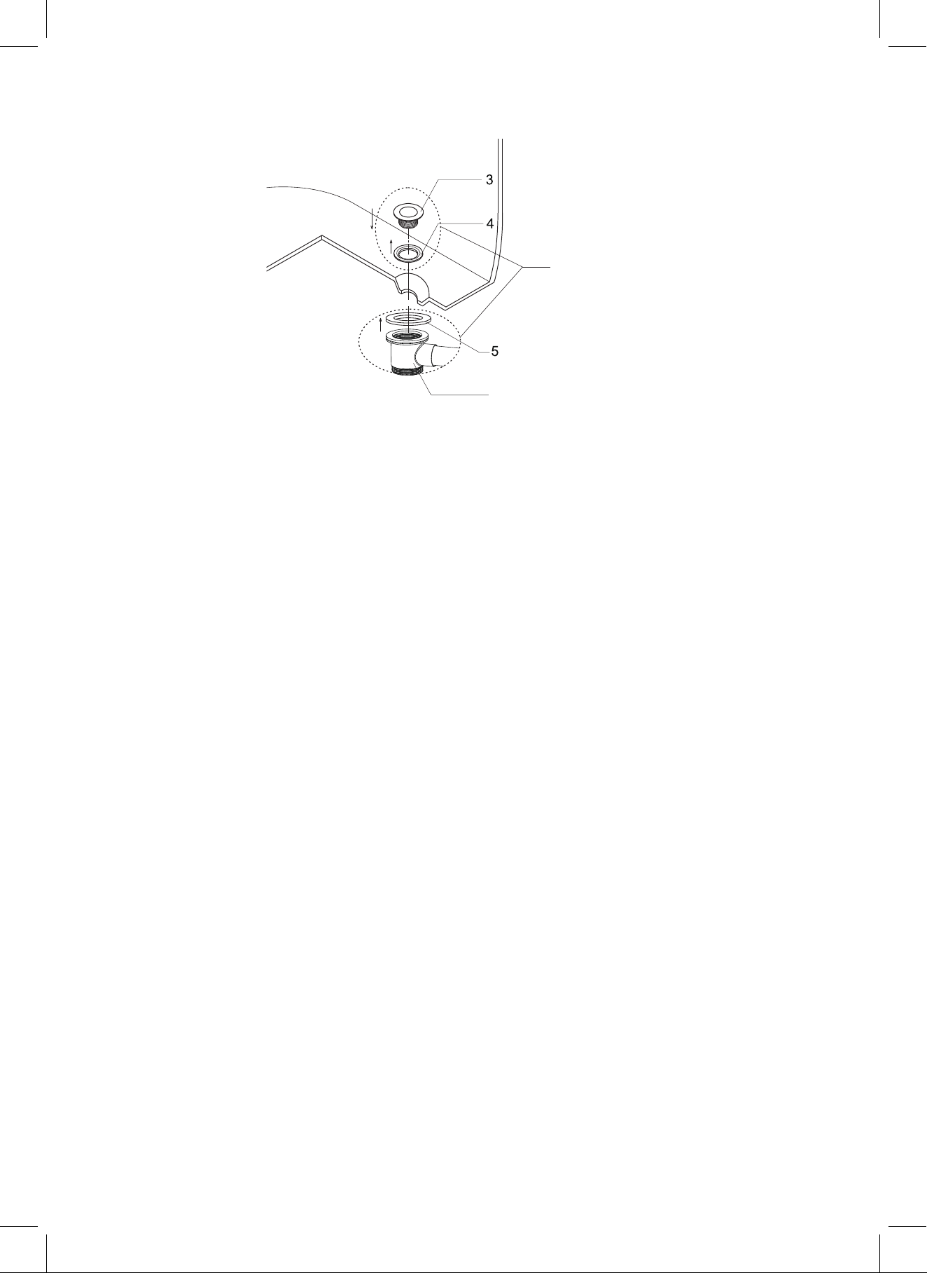
The installation steps below are for drain model A1840-0.
Strainer
Rubber Gasket
A1840-0
Flat Rubber Gasket
Connector
7
12. Put the rubber gasket (#4) onto the strainer (#3)
13. Put the rubber gasket and strainer through the pre-drilled drain hole.
14. Put the flat rubber gasket (#5) onto the connector (#7).
15. Connect the connector with the flat rubber gasket, strainer, and rubber gasket and tighten them by
hand. Then use a wrench to tighten the connector.
 Loading...