

Page 1
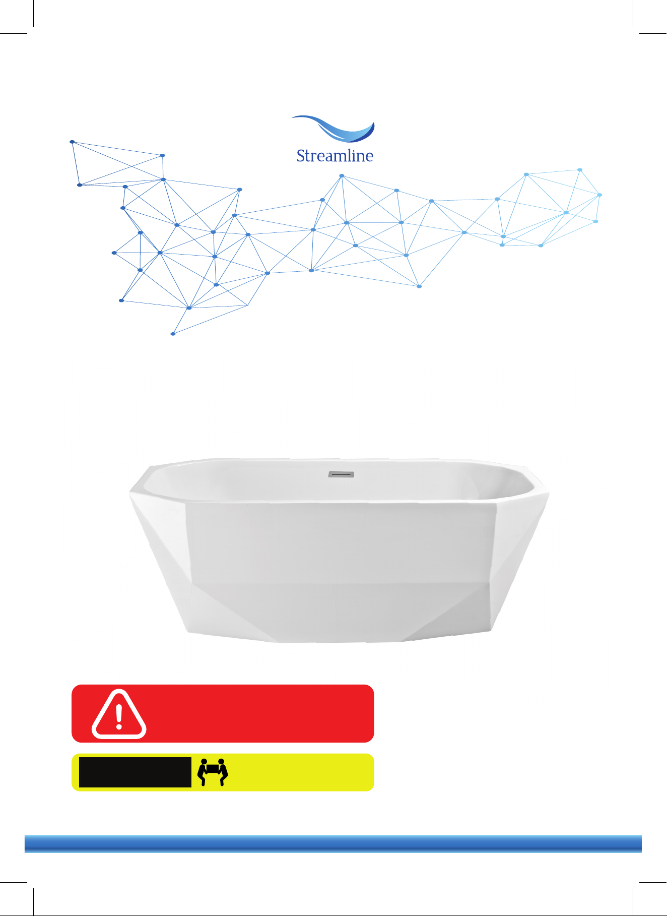
FREESTANDING BATHTUB SERIES
OWNER'S MANUAL &
INSTALLATION GUIDE
READ ENTIRE INSTALLATION GUIDE
PRIOR TO INSTALLING THE BATHTUB
THIS BATHTUB SHOULD ONLY BE
INSTALLED BY A CERTIFIED PLUMBER
CAUTION!
QUESTIONS ON PRODUCT, INSTALLATION, RETURNS? PLEASE CONTACT
streamlinebath.com
TWO PEOPLE ARE REQUIRED
TO LIFT THE BATHTUB
(310) 935-0028
Page 2
PRIOR TO INSTALLING
These products must be installed by a fully insured and licensed plumber only.
Installation of any product by anyone other than fully insured and licensed plumber shall void limited warranty.
We are not responsible for any local code compliance for this product.
Building and plumbing codes may vary state-to-state.
Streamline shall not be held liable for any and all incidental damages or flood caused due to use of this product.
Streamline shall not be held liable for any and all fees stemming from cost of installation, re-installation, removal,
subsequent damage, or transportation in a case of a product defect.
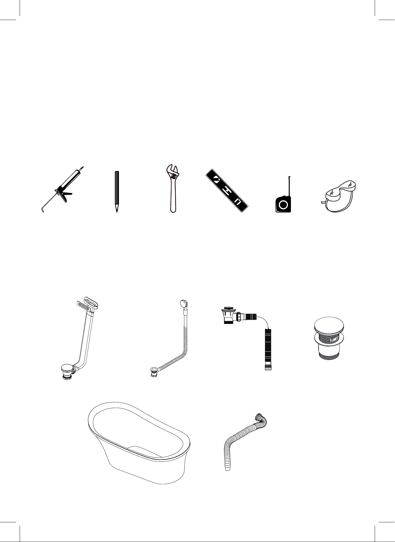
TOOLS REQUIRED
Silicone
Adjustable Key Measuring Tape Safety GlassesPencil Level Bar
WHAT'S IN THE BOX
Please note:
Different bathtub models have different drain models. Please see the next page to determine which drain model
applies to the bathtub model that you have purchased.
(Pre-installed)
Model A1040-F+ (A604)
(Pre-installed)
Model A1040-C
(Pre-installed)
Model A1840-0
N1606
athtub F
B
lexible Hose*
*All models except N1606 come with a flexible hose.
Page 3
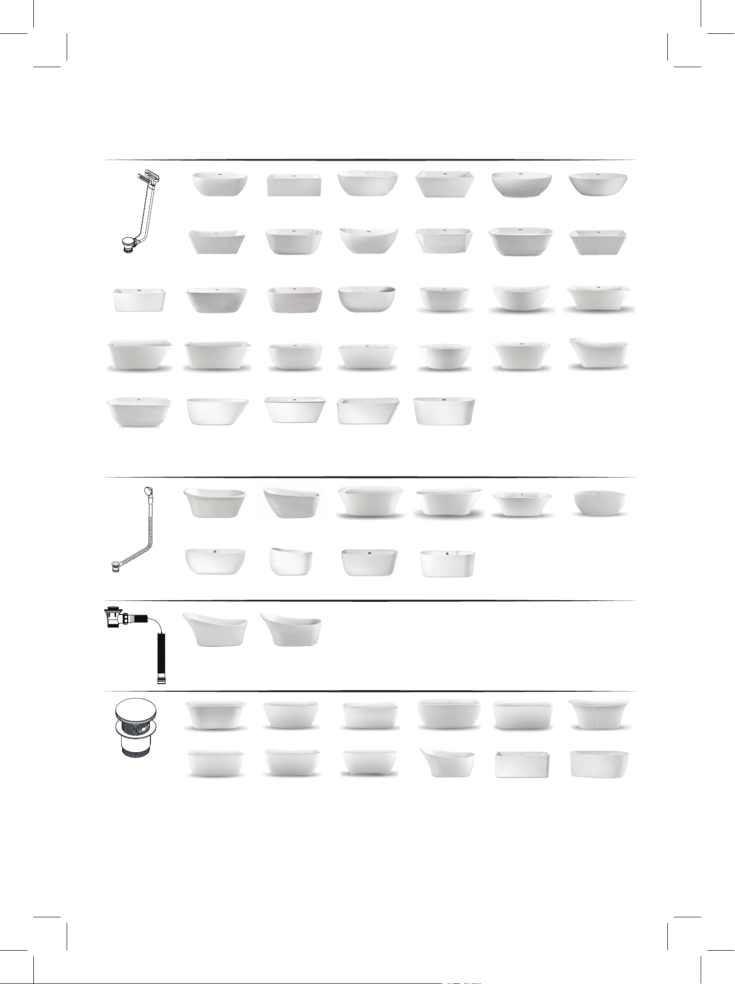
DRAIN MODEL COMPATIBILITY
FREESTANDING BATHTUB
N-140-60FSWH-FM N-380-63FSWH-FM
A1040-F+ (A604)
N-682-63FSWH-FM N-700-59FSWH-FM
N-1201-59FSWH-FM
N-662-59FSBLU-FM
N-663-67FSBL-FM
N-664-59PRWH-FM
N-540-62FSWH-FM
N-541-67FSWH-FM
N-542-70FSWH-FM
N-701-67FSWH-FM
N-1221-59FSWH-FM
N-1780-59-FSWH-FM N-2000-59FSWH-FM N-2020-63FSWH-FM N-2180-62FSWH-FM
N-1781-63FSWH-FM N-2001-63FSWH-FM
N-260-66FSWH-FM
N-261-62X30FSWH-FM
N-262-58FSWH-FM
N-560-59FSWH-FM
N-561-67FSWH-FM
N-562-71FSWH
N-780-59FSWH-FM
N-1241-59FSWH-FM N-1261-59FSWH-FM
N-300-59FSWH-FM N-320-60FSWH-FM
N-580-62FSWH-FM
N-581-66FSWH-FM
-FM
N-801-59FSBL-FM
N-802-67FSBL-FM
N-321-70FSWH-FM
N-620-63FSWH-FM
N-621-59FSWH-FM
N-622-67FSWH-FM
N-880-59FSWH-FM
N-881-63FSPRWH-FM
N-882-67FSBL-FM
N-1301-59FSWH-FM N-1321-59FSWH-FMN-1220-67FSWH-FM
N-381-67FSWH-FM
N-660-59FSWH-FM
N-661-67FSWH-FM
N-940-75FSWH-FM
N-420-63FSWH-FM
N-421-67FSWH-FM
N-681-67FSWH-FM
N-1000-71FSWH-FM
N-1340-67FSWH-FM
A1040-C
A1840-0
N1606
N-721-67FSWH-FM
N-1800-67FSWH-FM
N-460-63FSWH-FM
N-1560-59FSWH-FM N-1660-59FSWH-FM
N-1700-59FSWH-FM
N-1701-67FSWH-FM N-1721-67FSWH-FM
N-280-59FSWH-FM
N-281-67FSWH-FM
N-2040-51FSWH-FM
N-820-59FSWH-FM
N-821-63FSWH-FM
N-822-67FSWH-FM
N-1760-55FSWH-FM
N-1580-59FSWH-FM N-1600-59FSWH-FM N-1620-59FSWH-FM N-1640-59FSWH-FM
N-1720-59FSWH-FM N-1740-59FSWH-FM N-1760-55FSWH-FM N-2002-67FSWH-FM N-2080-59FSWH-FM
N-1160-59FSWH-FM
N-1161-59FSBL-FM
N-2060-59FSWH-FM N-2120-59FSWH-FM
N-1520-61FSWH-FM
N-1521-65FSWH-FM
N-1522-69FSWH-FM
N-1761-59FSWH-FM
N-1762-63FSWH-FM
N-1060-59FSWH-FM
N-1680-67FSWH-FM
Page 4
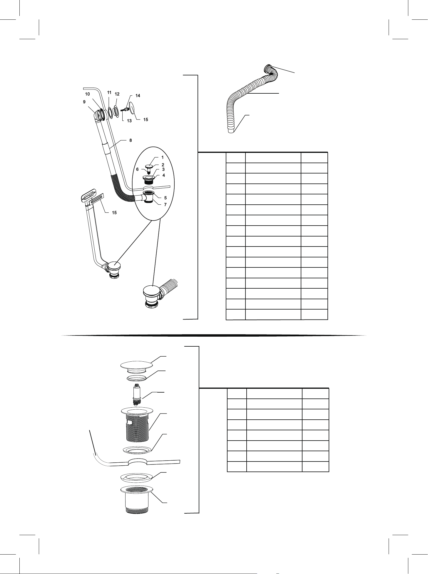
DRAIN DIAGRAMS
Model: A1040-C
Flexible Hose
Drain Diameter: 1.25"
Model: A1040-C
Pop-Up Cover
1
O Ring
2
Strainer
3
Rubber Gasket
4
Flat Rubber Gasket
5
Cartridge
6
Pre-Installed to Bathtub
Overall Tube Length: 47''
ITEM Qty.No.
1
1
1
1
1
1
Model: A1040-F+(A604)
Model: A1840-0
Tee
7
Coupling Pipe
8
Overflow Body
9
Backside Gasket
10
Upper Gasket
11
Strainer
12
Pin
13
Pin Bolt
14
Overflow Plate
15
1
1
1
1
1
1
1
1
1
1
2
Model: N1606*
3
ITEM Qty.No.
Thickness of Bathtub
Model: N1606
1
Pop-Up Cover
4
5
6
2
O Ring
3
Cartridge
Strainer
4
Rubber Gasket
5
Flat Rubber Gasket
6
Tee
7
* Please note, bathtub models with this drain assembly
do NOT come with a flexible hose.
1
1
1
1
1
1
1
7
Page 5
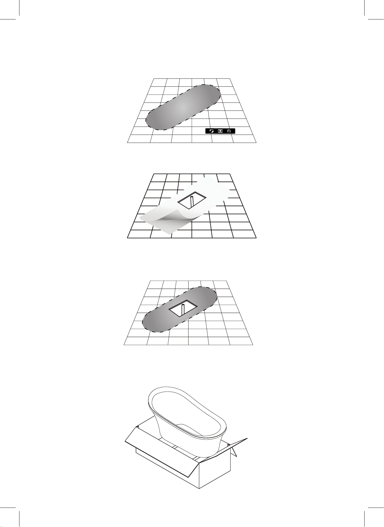
BATHTUB INSTALLATION
1. Ensure that the floor at the installation site has sufficient floor support and is level.
2. Waterproofing the floor is highly recommended.
3. Determine the location of the drainpipe on the floor by taking measurements of the drain and waste
location underneath the unit. Clean the drain hole area in preparation of setting the drain. The area
should be dry & free from any debris.
4. Remove the bathtub from its box. It is recommended that the bathtub is carried by a minimum of
two people. Ensure to carry and set down the bathtub only in the upside-down position.
Page 6
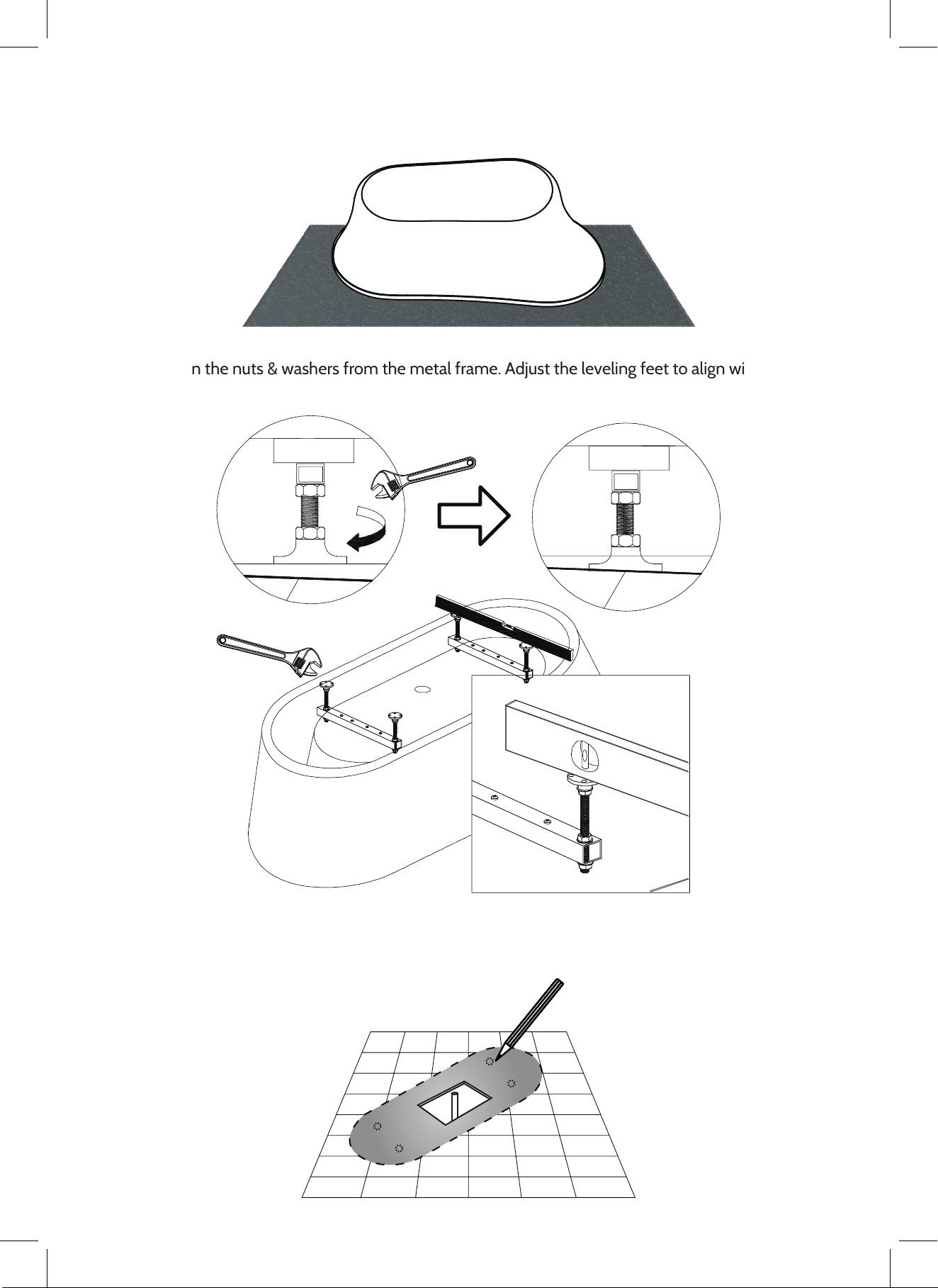
5. Gently place the bathtub in the upside-down position on a tarp or cardboard sheet in order to avoid
contact with any rough surface.
6. Loosen the nuts & washers from the metal frame. Adjust the leveling feet to align with the bathtub’s
bottom as well as the floor and then tighten the washer and nuts.
7. Ensure to mark all positions of leveling legs on the floor using a pencil. Move the bathtub into the
desired location near the drainpipe.
Page 7
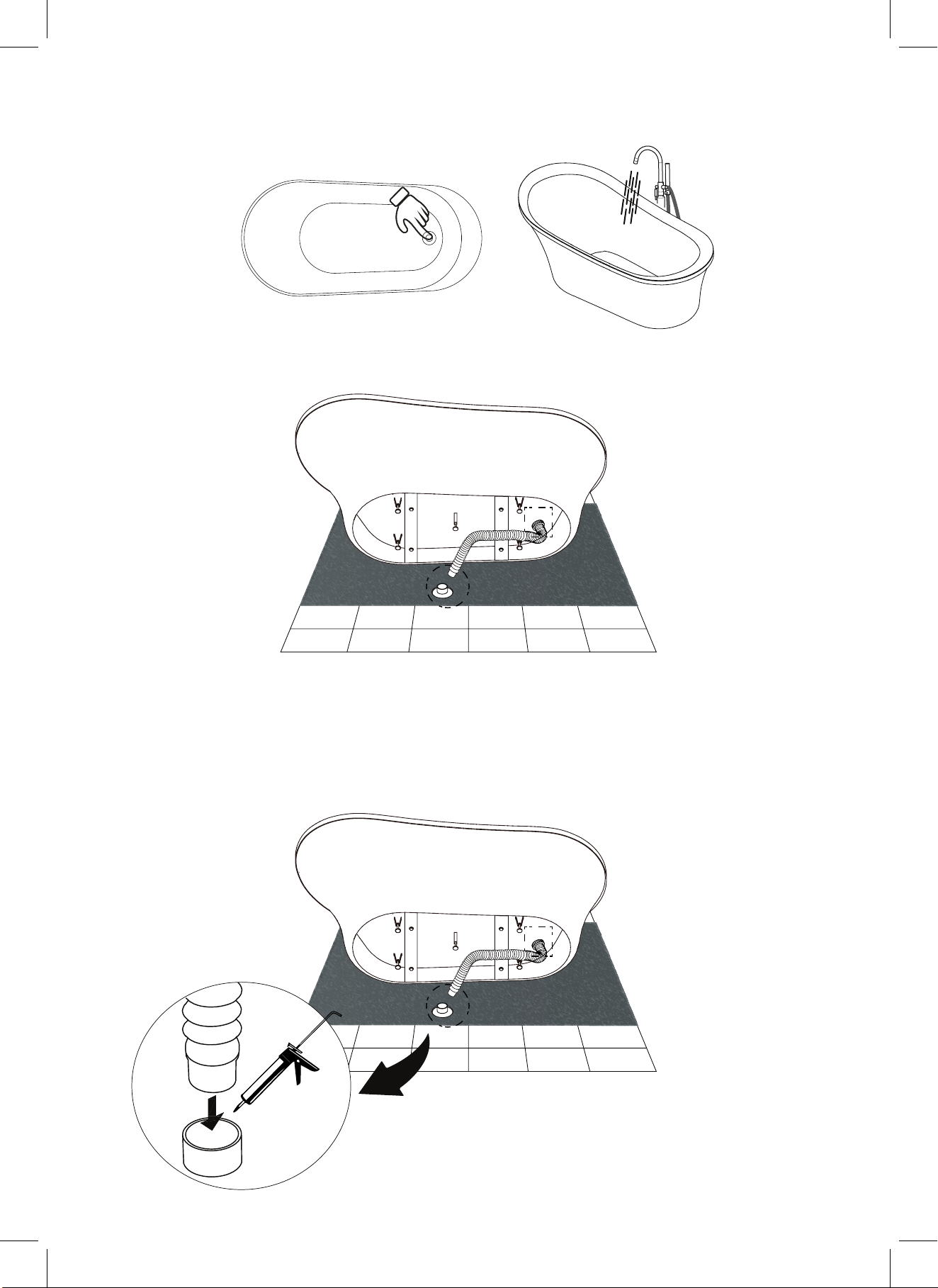
8. Before proceeding with installation, push the pop up into a close position and fill the bathtub above
the overflow [Note: some models may not have an overflow] to test for overflow and drain leakage.
9. Proceed to place the provided flexible drain hose into the floor drain.
10. Please note, the flexible hose is a basic way that we provide to connect to the end plumbing in a
home. The plumbing installation in every home differs, so please consult with a certified plumber
to see if the plumbing in your home is compatible with using a basic flexible hose.
11. Seal the connection by using a PVC pipe sealant to join the parts together.
Page 8
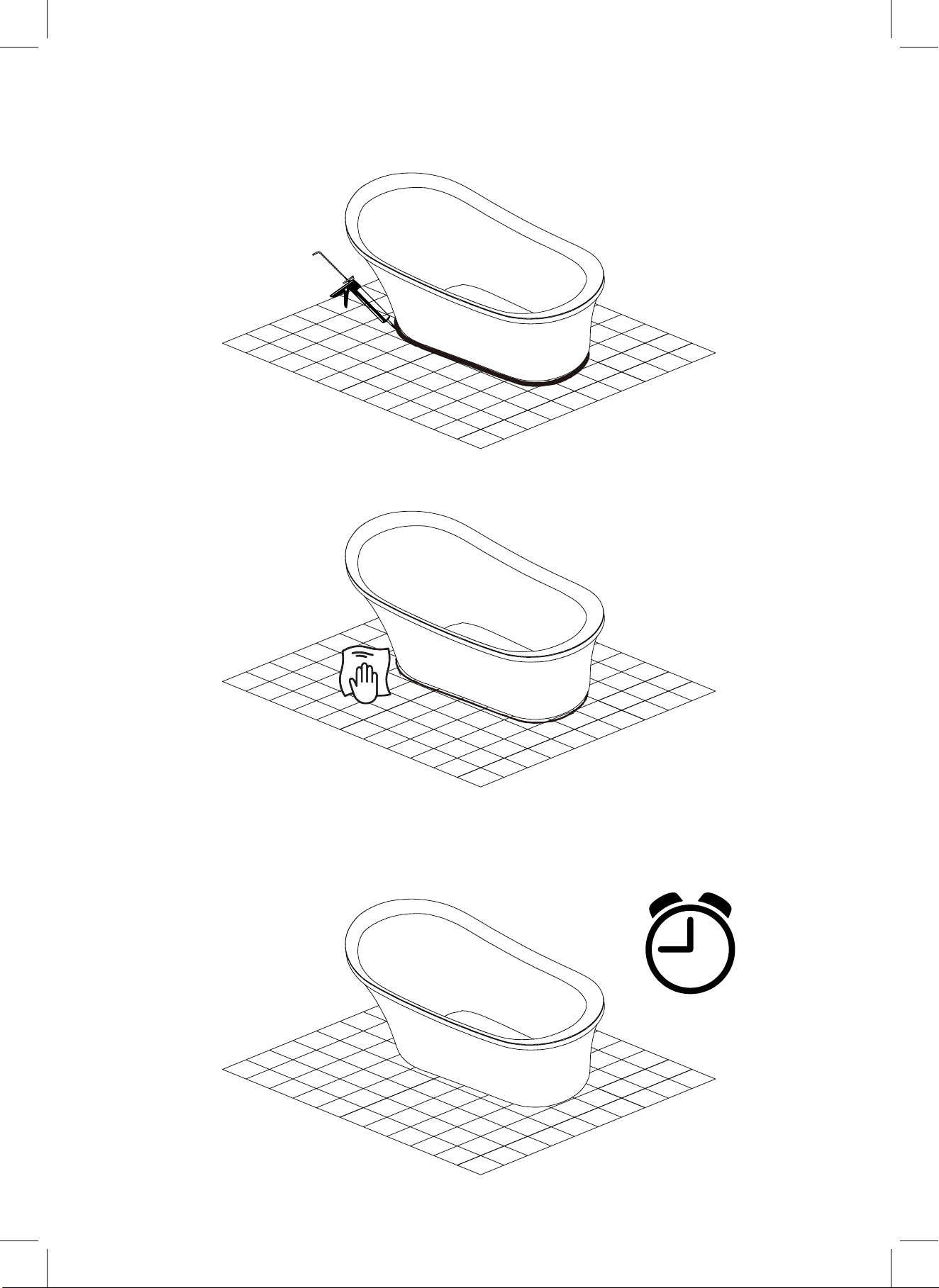
12. Apply silicone along the bottom of the bathtub In order to create an airtight seal. Then apply a bead
of tub & tile caulk around the edges of the base.
13. With the bathtub now in place, wipe off any excess silicone, tub & tile caulk where the bathtub meets
the floor.
14. Allow for up to 24 hours for the adhesive material to set.
24h
Page 9
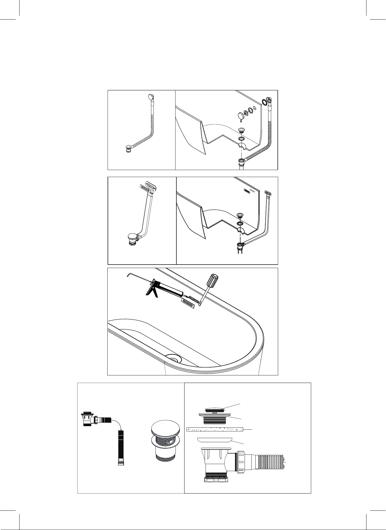
INTERNAL DRAIN INSTALLATION DIAGRAM
Please Note: The drain may have already been installed by the manufacturer prior to shipment.
These drawings are to only show how the drain connects to the bathtub.
Model
A1040-F+ (A604)
Model
Model A1040-C
Pop-Up Cover
Washer
Model
Model A1840-0
Thickness of Bathtub
Washer
Model: N1606
Page 10
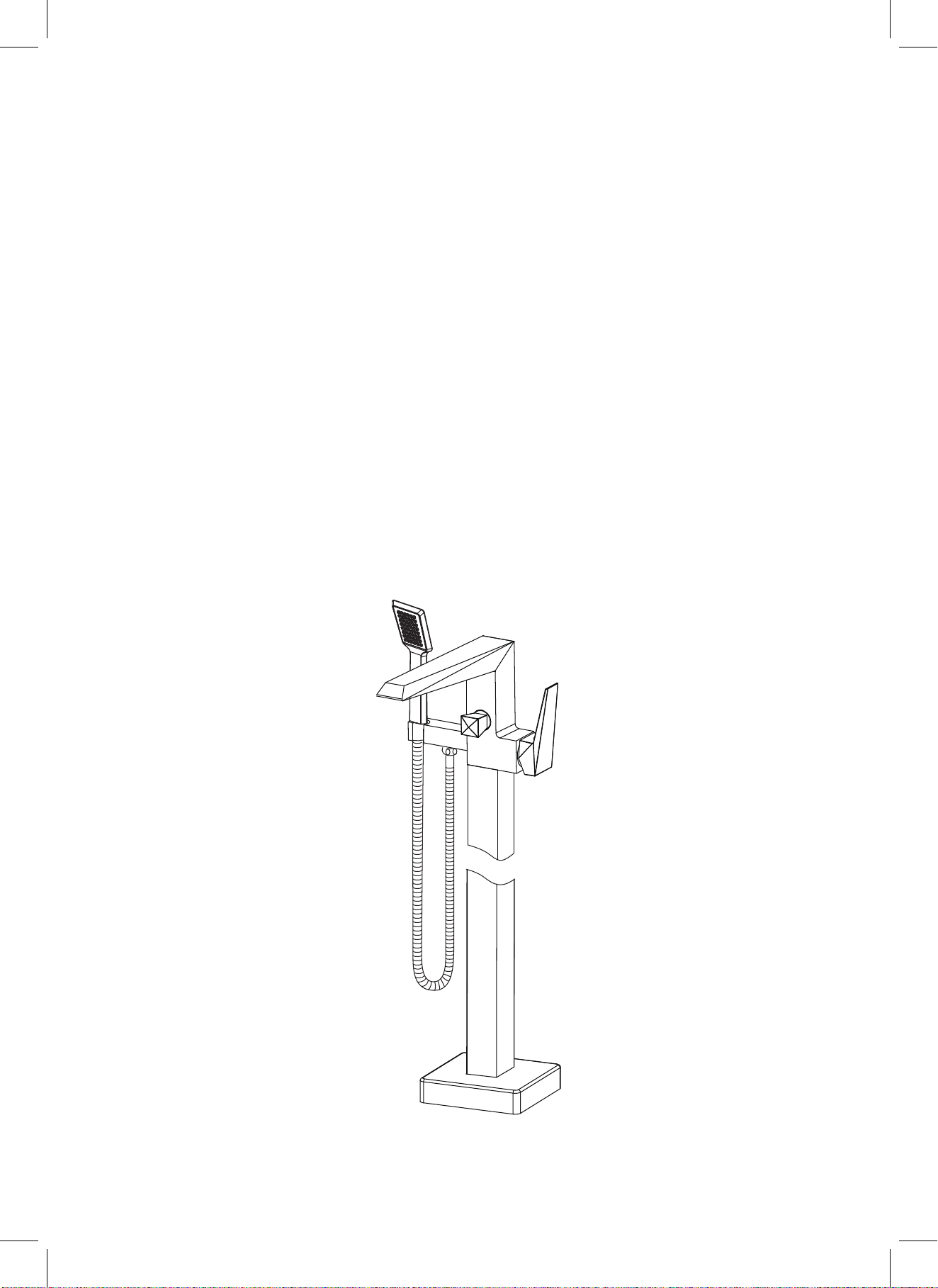
SINGLE HANDLE FREESTANDING
TUB&SHOWER FAUCET
H-100-TFMSHCH
Page 11
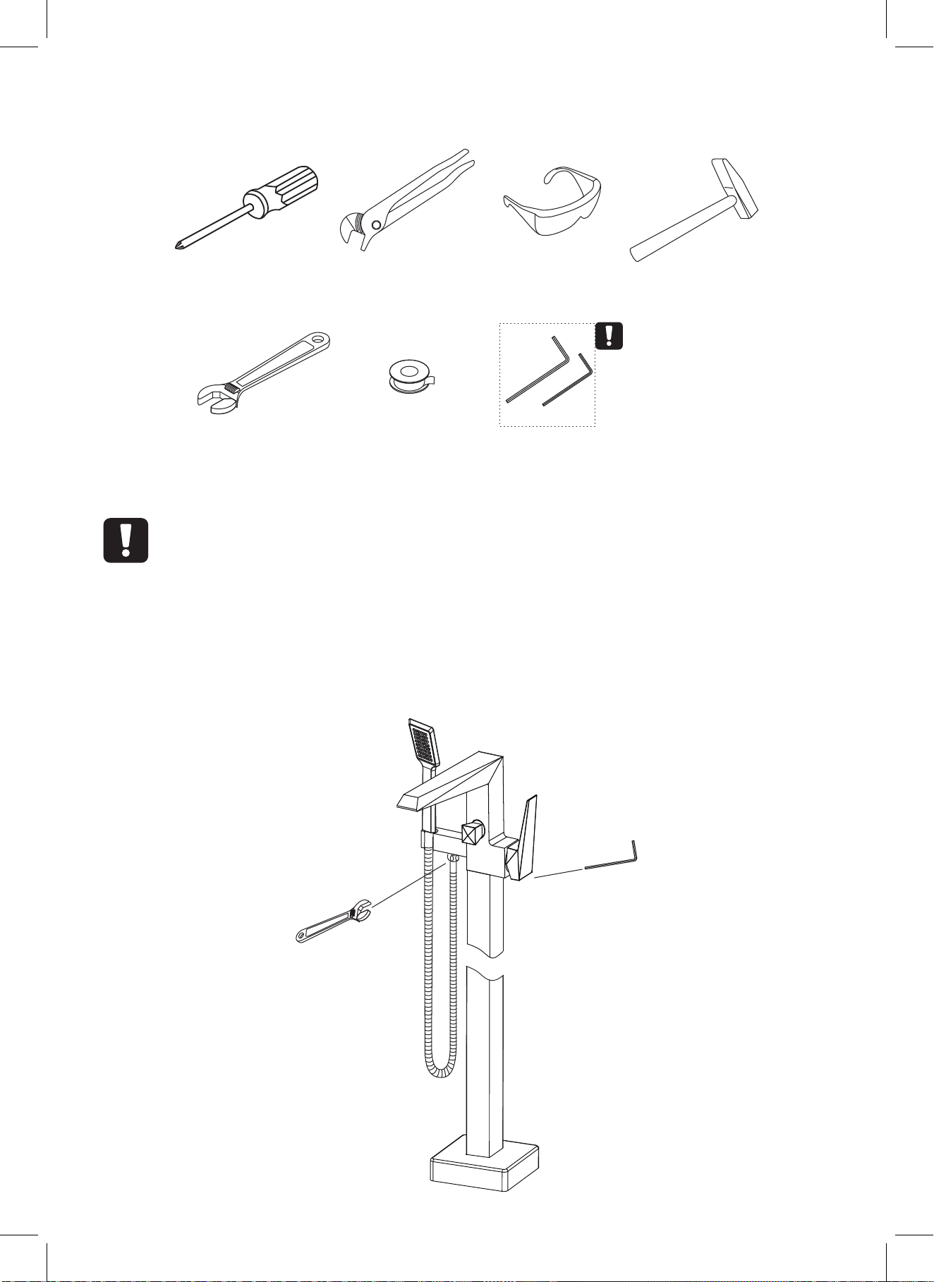
RECOMMENDED TOOLS
Screwdriver Channel Locks Goggles
Adjustable Wrench Teflon tape Allen key
ATTENTION:
for easy installation, you will need:
1. To read all the installation instruction completely before
beginning.
2. To read all the warning, attention and maitenance
information.
Hammer
WARNING:
Please keep the
tool for future use!
THE TOOLS MIGHT BE APPLIED TO THE FOLLOWING PLACES:
Page 12
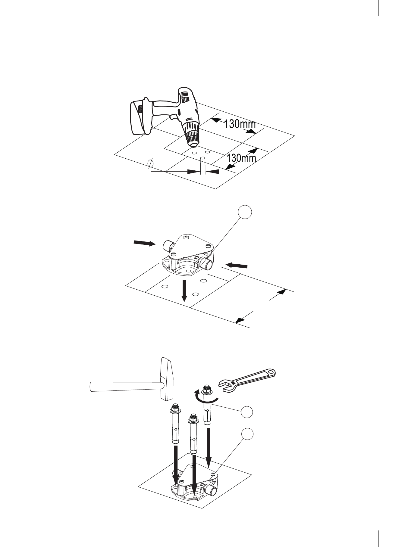
FAUCET INSTALLATION
1. Drill one hole of 130mmx130mm max and drill 3 holes with 80mm diameter as shown.
80
mm
2. Align the base ① with the holes exactly as shown.
1
HOT WATER
COLD WATER
MAX 130mm
3. Insert the expansion anchors ① into the holes on the base ② with a hammer, tighten with
adjustable wrench.
1
2
Page 13
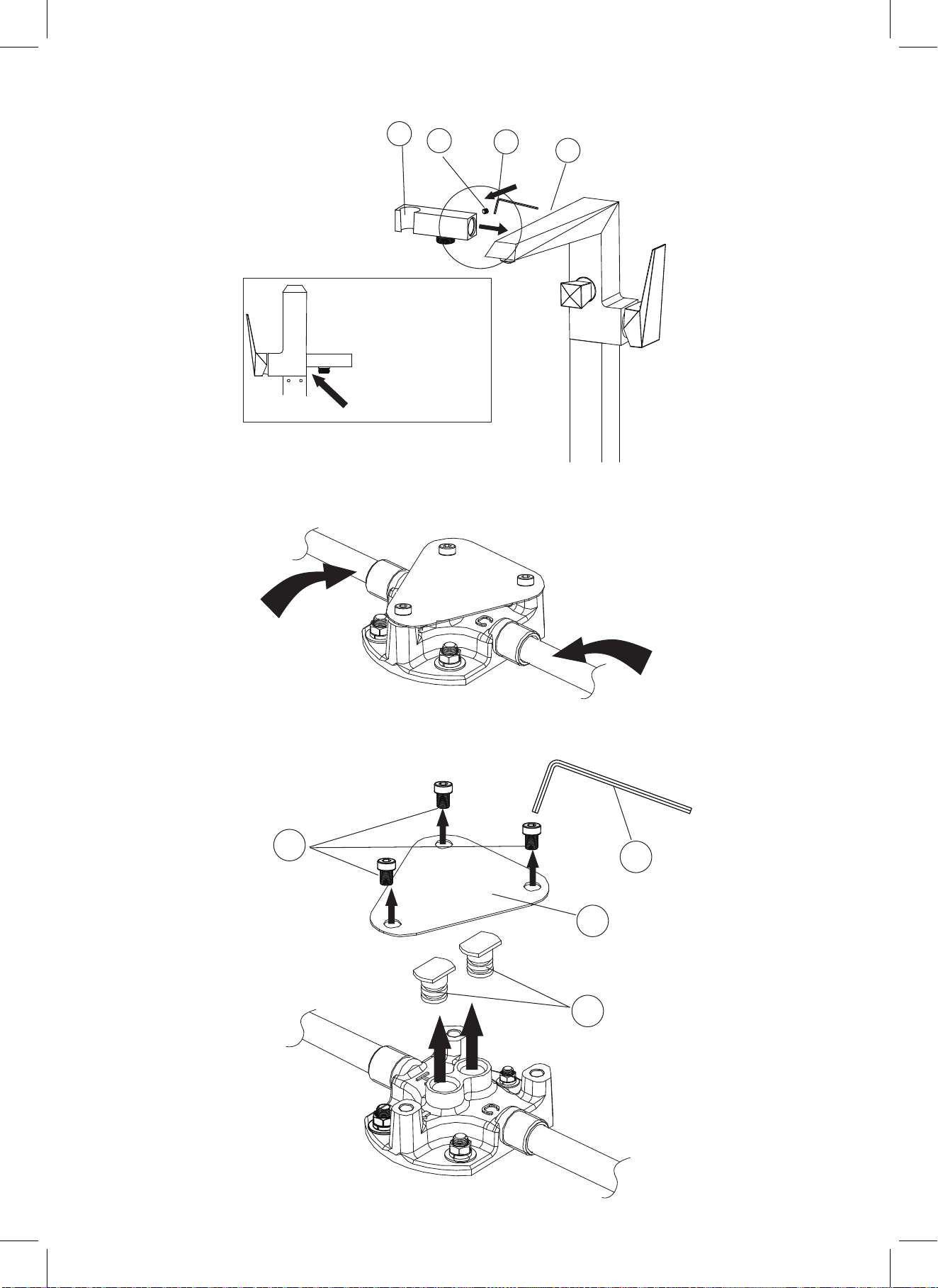
4. Tighten the shower holder① into faucet body④ with a screw② and Allen key③.
1
2
INSTALLATION
LOCATION
5. Connect hot and cold supply lines and test by opening water lines.
3
4
HOT WATER
COLD WATER
6. If there are no leaks, remove the 3 screws (1) with the Allen key (2), then remove plate (3) and
nuts (4) as shown.
1
2
3
4
Page 14
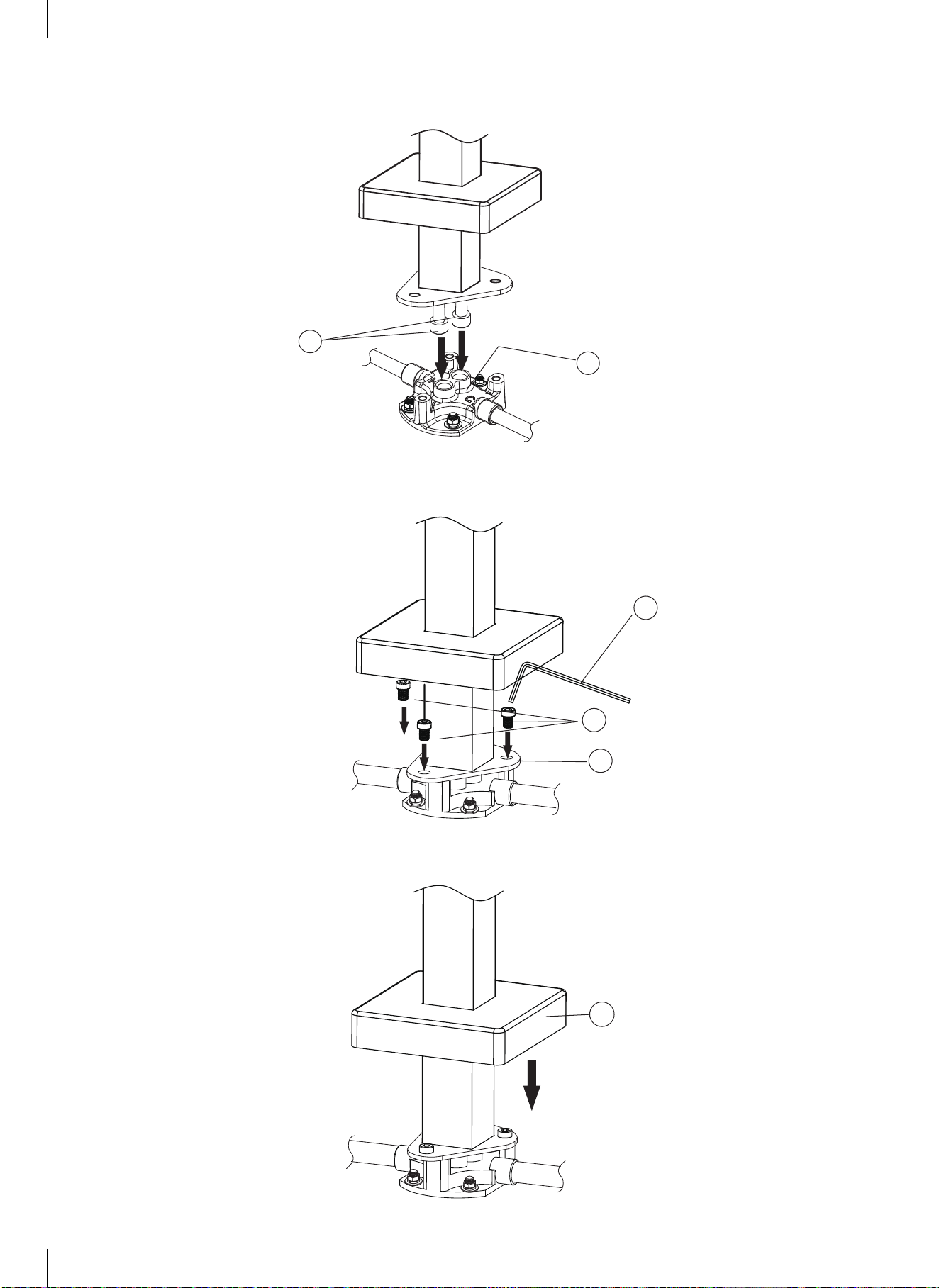
7. Connect hot water flexible hose(1) and cold water flexible hose(1) to the base (2) correctly as shown.
1
2
8. Insert 3 screws (1) into holes on the plate (2), Tighten with allen key (3).
9. Put down cover (1) and complete installation.
3
1
2
1
Page 15
CHECKING AND TESTING
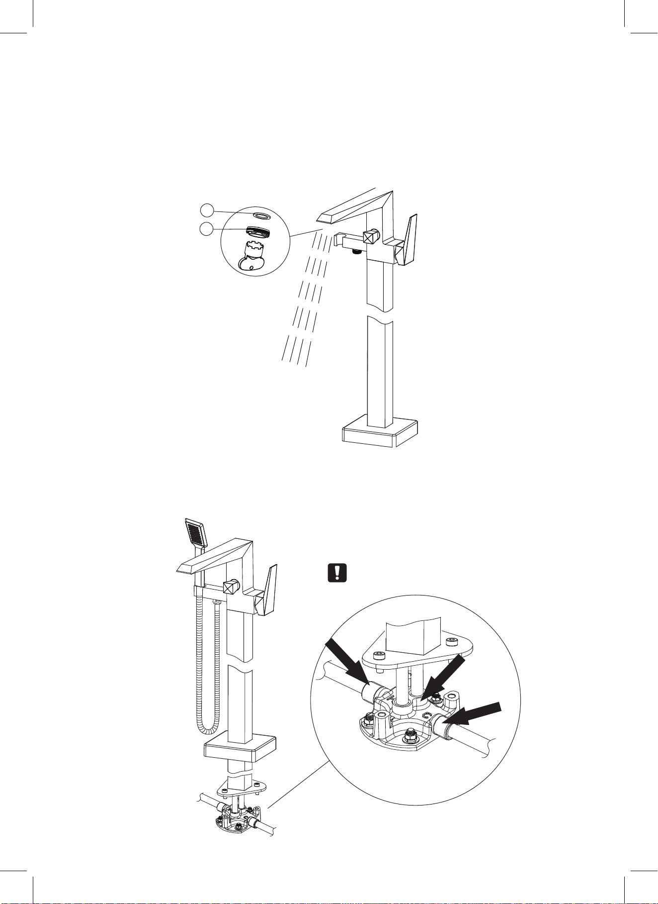
1. Remove the aerator ② with aerator wrench, take out the o-ring ① too.Turn the faucet handle all the
way on, turn on hot and cold water supply and flush water lines for one minute.Reinstall aerator
with aerator wrench.
1
2
2. Check all connections at arrows for leaks, re-tighten it if necessary.
BUT DON'T OVERTIGHTEN
Page 16
MAINTENANCE
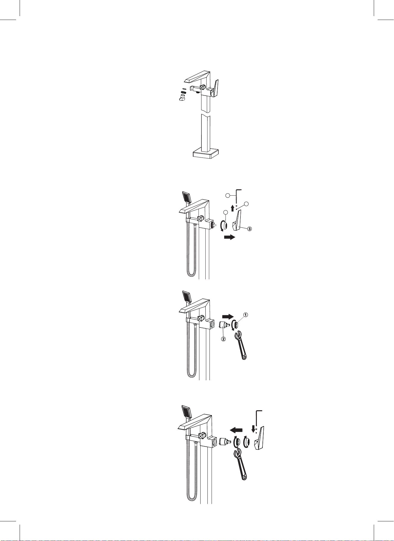
A. If there is splash or low flow rate,please remove the aerator with the wrench and clean the debris.
B. If faucet leaks from the handle or drips from spout, please replace cartridge following the following
steps:
1. Disassemble the screw② with allenkey①, take out the handle③, then remove the trim cap④.
1
2
4
3
2. Unscrew the cartridge nut① with adjustable wrench, then take out the old cartridge②.
1
2
3. Place a new cartridge in the cartridge seat, then screw the cartridge lock nut and assemble the handle
by securing the screws. Repeat the above steps for the other cartridge if necessary.
Page 17
CLEANING AND CARE
Daily cleaning and care are required in order to keep the product shining and properly working.
1. Clean it with water and dry it with soft cloth.
2. Clean the product with gentle liquid or glass cleaner.
3. Don't use acid cleaner.
4. Don't clean with abrasive material, abrasive paper or knife.
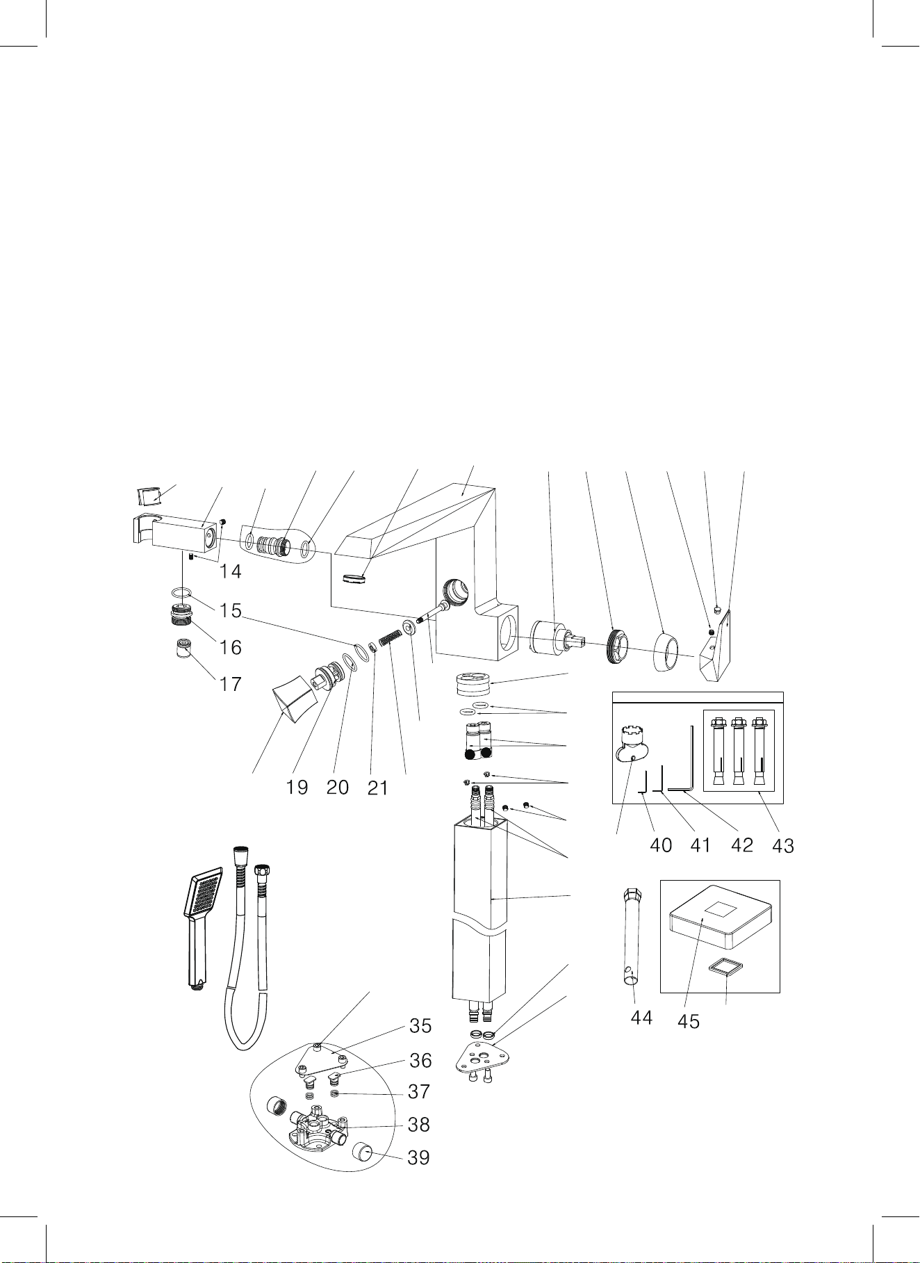
PARTS LIST
1 3
1 2
1 8
1 1
1 0
9
8
2 4
7
6
2 5
4
5
3
2
1
2 6
2 3
2 7
2 2
2 8
2 9
3 0
4 7
3 4
3 1
3 2
3 3
4 6
 Loading...