

Page 1
840 Jury Ct.
San Jose, CA 95112
Tel: 888.604.5234
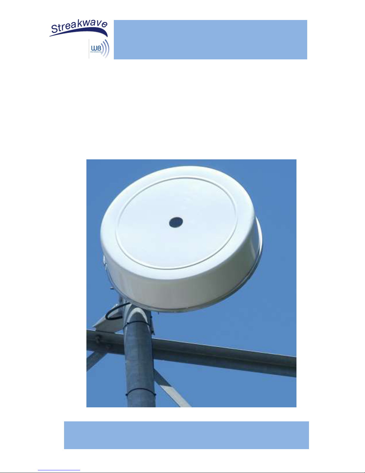
Thank you for purchasing WB Manufacturing’s Optic Series
Antenna. Follow the instructions below for proper
installation of the antenna. A 9/16” wrench and Phillips
screwdriver will be required to complete assembly.
INSTALLATION GUIDE - Optic Series Antenna
www.streakwave.com
Page 2
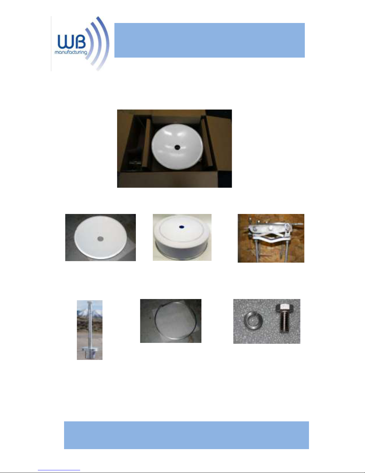
Step 1: Remove the reflector and its parts from the
packaging. Be sure that all the components are inside.
*(Feedhorns are sold, packed and shipped
separate from the antenna).
Reflector (1)
Band Clamp (1)
Radome (1)
Feedhorn (1)*
Mount Assembly (1)
3/8”x1” Stainless Steel Bolt, Washer (3)
840 Jury Ct.
San Jose, CA 95112 Tel: 888.604.5234
www.streakwave.com
Page 3
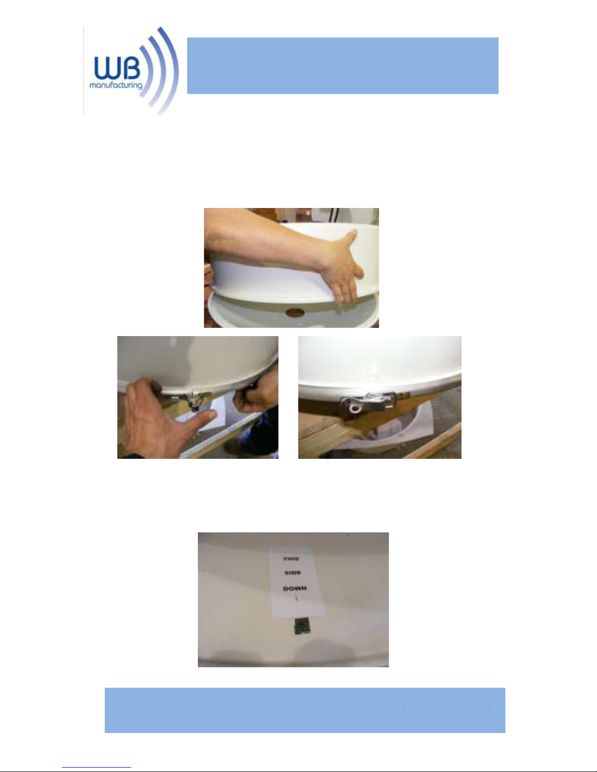
Step 2: During shipping the reflector is positioned inside
the radome. Remove the band clamp, flip the reflector
over, and use the band clamp to re-attach the radome to
the reflector.
Note: Before fastening the band clamp, rotate
radome to ensure that the weep hole will be
positioned at the bottom.
840 Jury Ct.
San Jose, CA 95112 Tel: 888.604.5234
www.streakwave.com
Page 4
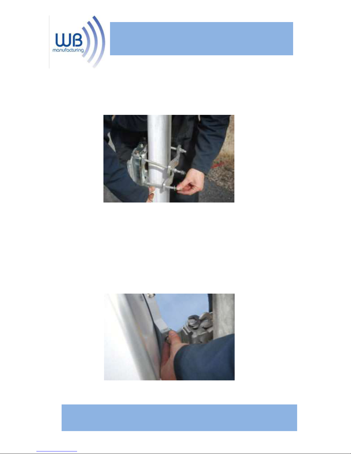
Step 3: Using the Tower Clamps (2) attach the Optic
antenna to the tower. Tighten the nuts securely.
Step 4: Use 3/8”x1” Stainless Steel Bolt and Washer (3)
to attach the antenna to the mount.
840 Jury Ct.
San Jose, CA 95112 Tel: 888.604.5234
www.streakwave.com
Page 5
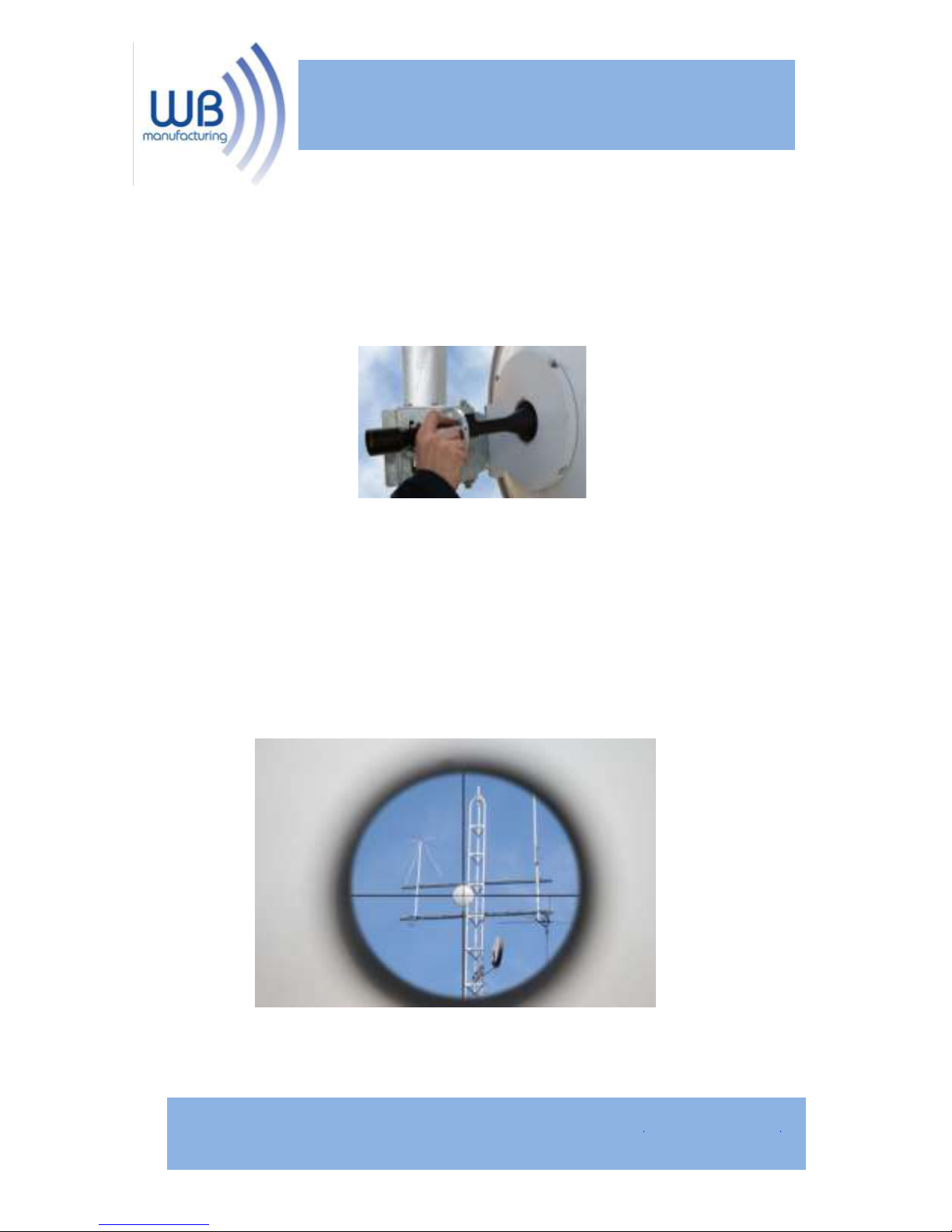
Step 5(Optional): The Optic antenna is designed to
work with an advanced aiming scope. If the scope is to
be used, insert the scope into the back of the antenna.
Once the scope is securely in place it can now be used
to more accurately aim the antenna. Use the AccuAim
Elevation and Azimuth adjustment bolts on the mount to
achieve pinpoint accuracy (shown in Step 6).
840 Jury Ct.
San Jose, CA 95112 Tel: 888.604.5234
www.streakwave.com
Page 6
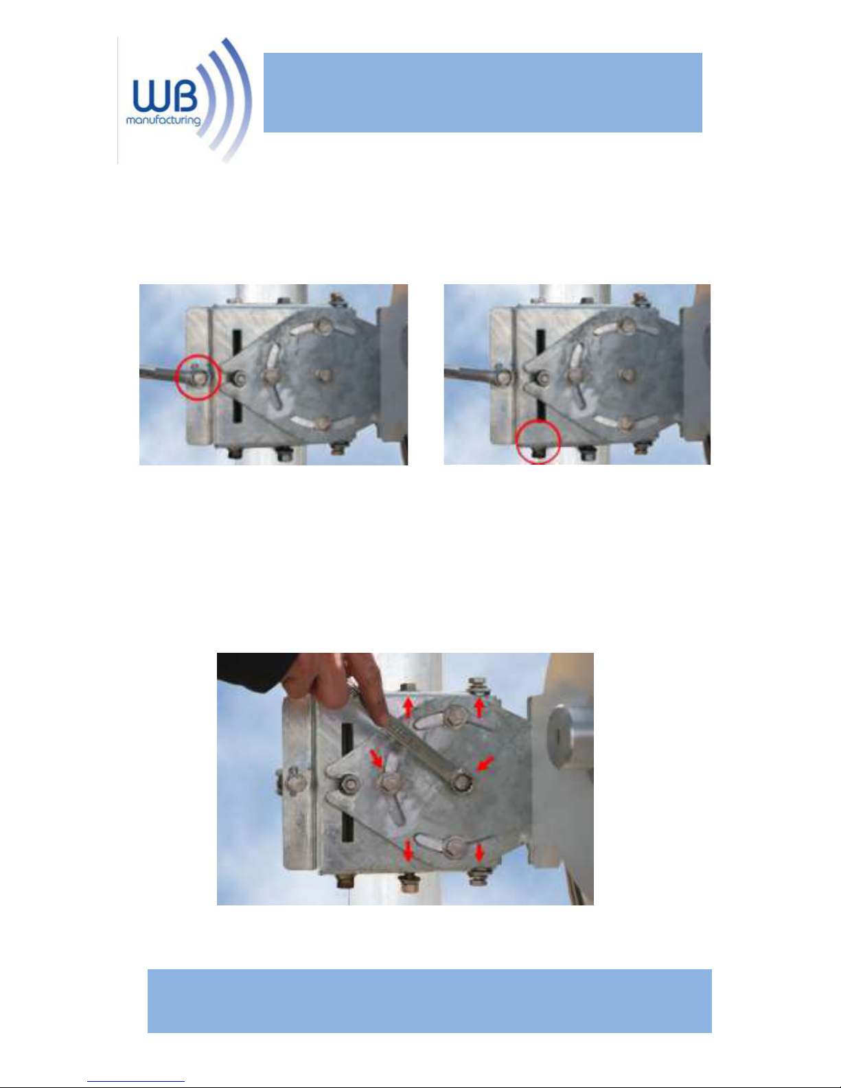
Step 6: Align the Optic antenna using the AccuAim
Elevation and Azimuth adjustment bolts located on the
mount.
Step 7: Once aiming is complete, securely tighten the
following bolts.
Azimuth
Elevaon
840 Jury Ct.
San Jose, CA 95112 Tel: 888.604.5234
www.streakwave.com
Page 7
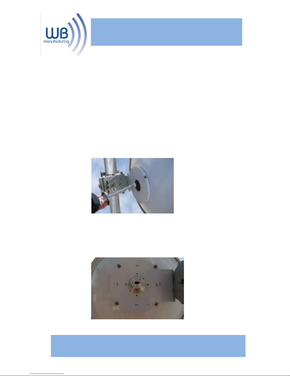
*The following steps will differ depending on the
radio you have selected to use with this Universal
Antenna.
Remec-Based Radios
Step A: Insert the feedhorn into the back of the
antenna. (Remove the scope (if used) from the antenna
and replace it with the feedhorn).
Line the grooves on the feedhorn up with the screws on
the ODU plate to insert completely. Then Twist into the
desired position.
840 Jury Ct.
San Jose, CA 95112 Tel: 888.604.5234
www.streakwave.com
Page 8
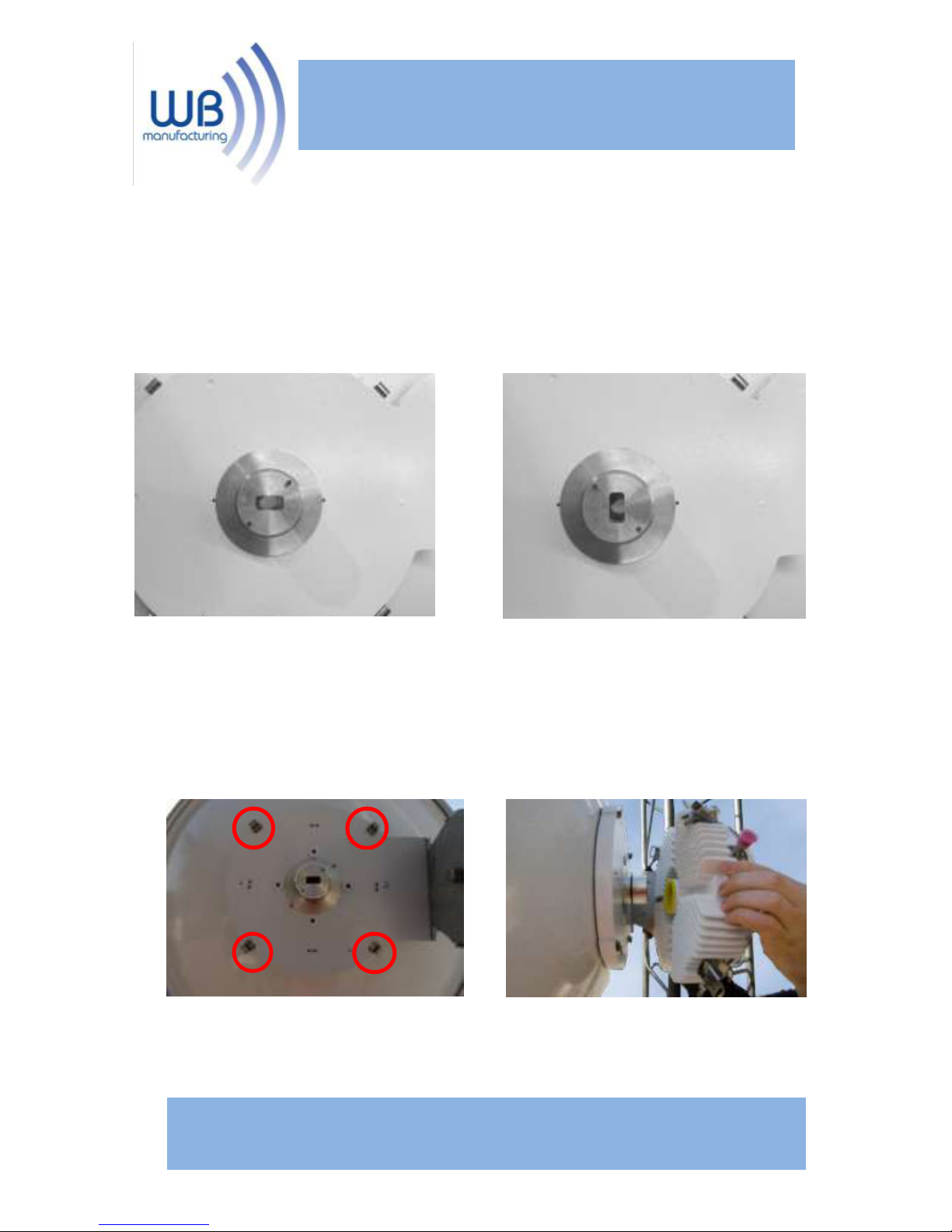
Note: The pictures below show the proper alignment for
vertical and horizontal polarity using a rectangular
waveguide. When using circular waveguide any
orientation of the feedhorn will work.
Step B: Attach the radio using the fasteners on the
ODU and the clips provided on the ODU plate. Be sure
Radio.
Vercal Polarity
Horizontal Polarity
840 Jury Ct.
San Jose, CA 95112 Tel: 888.604.5234
www.streakwave.com
Page 9
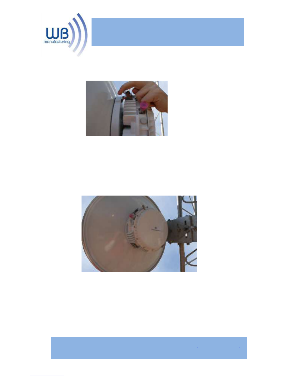
*Make sure all fasteners are secured tightly.
Installation of the Optic Series antenna is now
complete!
840 Jury Ct.
San Jose, CA 95112 Tel: 888.604.5234
www.streakwave.com
Page 10
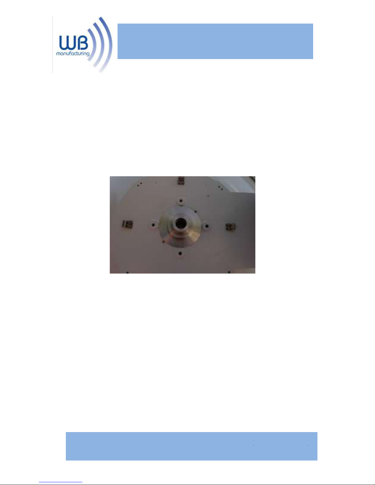
Dragonwave Radios
Step A: Insert the feedhorn into the back of the
antenna. (Remove the scope (if used) from the antenna
and replace it with the feedhorn). Line the grooves on
the feedhorn up with the screws on the ODU plate to
insert completely. Then Twist into the desired position.
Note: When using circular waveguide any orientation of
the feedhorn will work.
840 Jury Ct.
San Jose, CA 95112 Tel: 888.604.5234
www.streakwave.com
Page 11
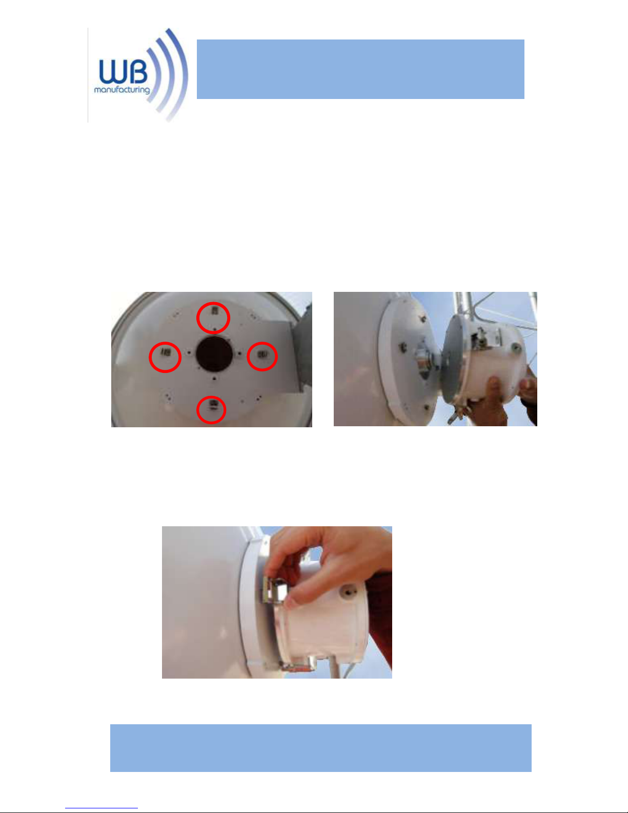
Step B: Attach the radio using the fasteners on the
ODU and the clips provided on the ODU plate. The
fasteners may need to be repositioned. Use the allen
wrench that came with the feedhorn to remove the clips.
Re-position them appropriately (As Shown Below).
*Make sure all fasteners are secured tightly.
840 Jury Ct.
San Jose, CA 95112 Tel: 888.604.5234
www.streakwave.com
Page 12
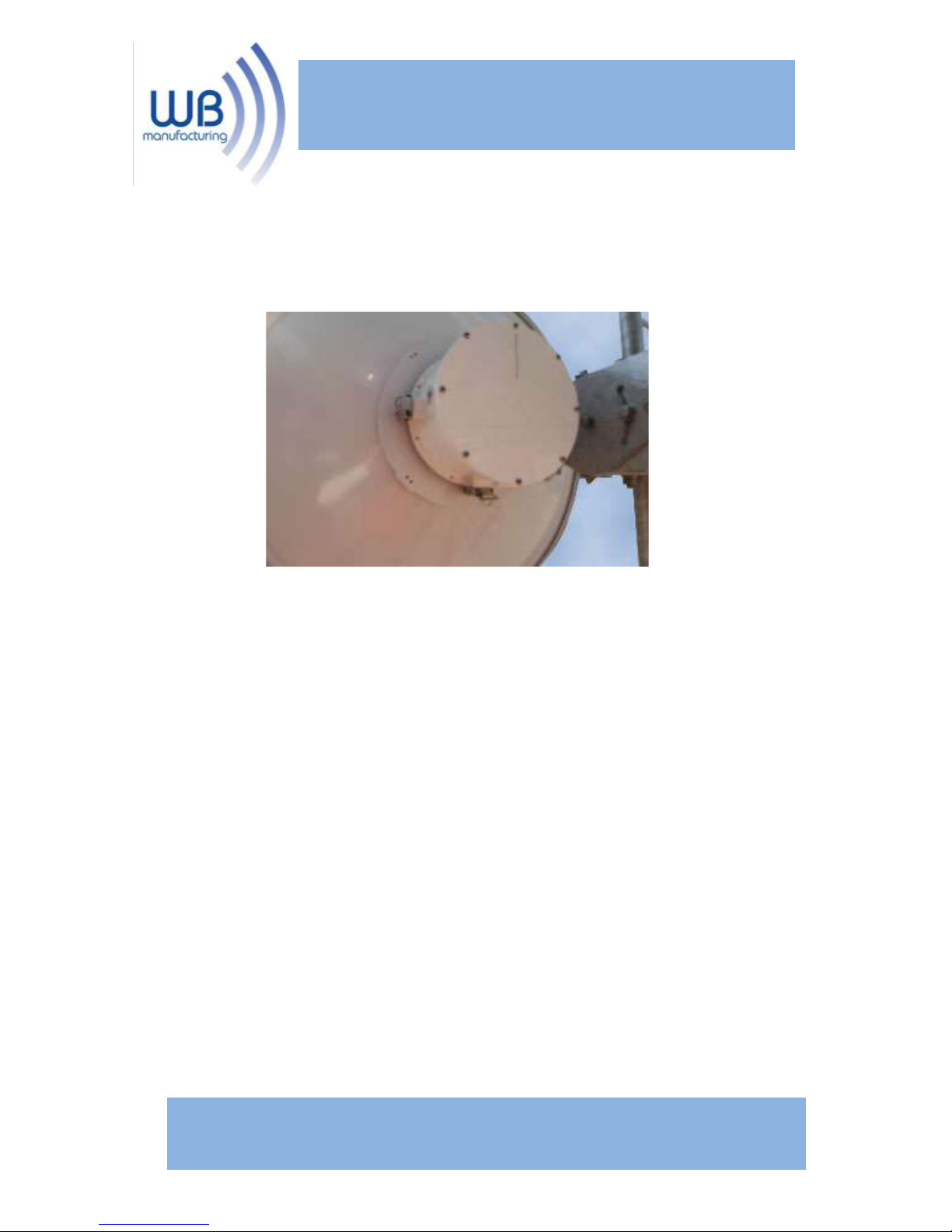
Installation of the Optic Series antenna is now
complete!
840 Jury Ct.
San Jose, CA 95112 Tel: 888.604.5234
www.streakwave.com
Page 13
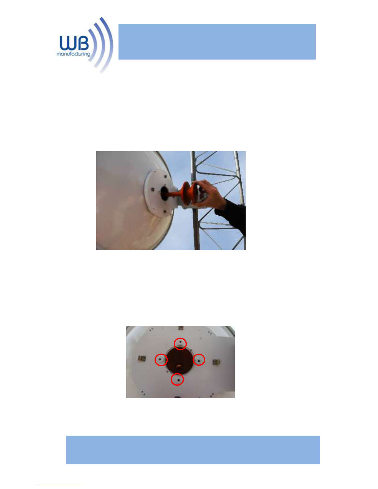
SAF Radios
Step A: Insert the feedhorn into the back of the
antenna. (Remove the scope (if used) from the antenna
and replace it with the feedhorn).
Step B: Attach the radio using the ¼’’x ½’’ bolts (4)
provided in the feedhorn packaging.
840 Jury Ct.
San Jose, CA 95112 Tel: 888.604.5234
www.streakwave.com
Page 14
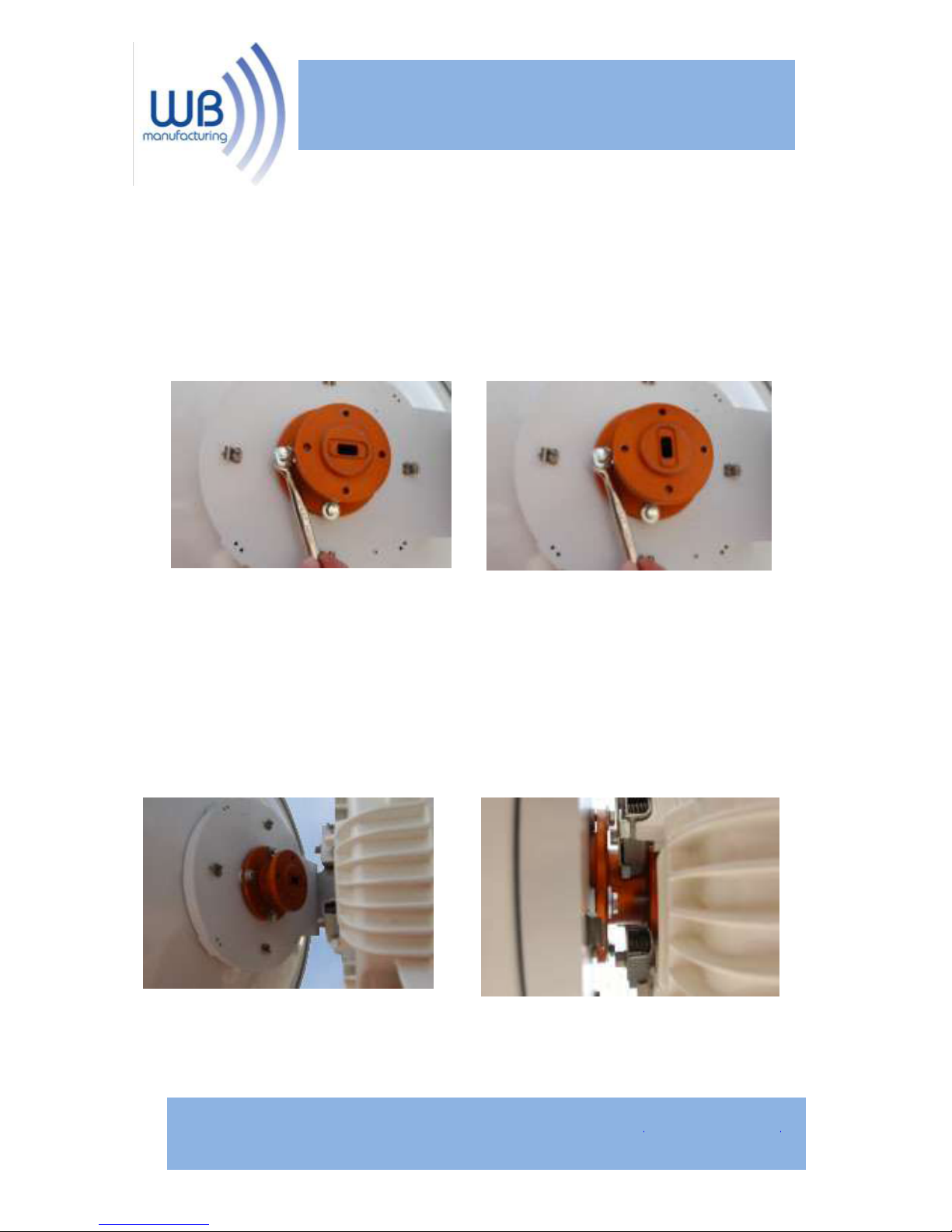
Note: The pictures below show the proper alignment for
vertical and horizontal polarity using a rectangular
waveguide. When using circular waveguide any
orientation of the feedhorn will work.
Step C: Align the bolts on the SAF Radio with the
corresponding holes on the feedhorn according to the
desired polarity. Using the tool SAF provides with the
radio, fasten the radio to the feedhorn.
Vercal Polarity
Horizontal Polarity
840 Jury Ct.
San Jose, CA 95112 Tel: 888.604.5234
www.streakwave.com
Page 15

Installation of the Optic Series antenna is now
complete!
840 Jury Ct.
San Jose, CA 95112 Tel: 888.604.5234
www.streakwave.com
 Loading...