

Page 1
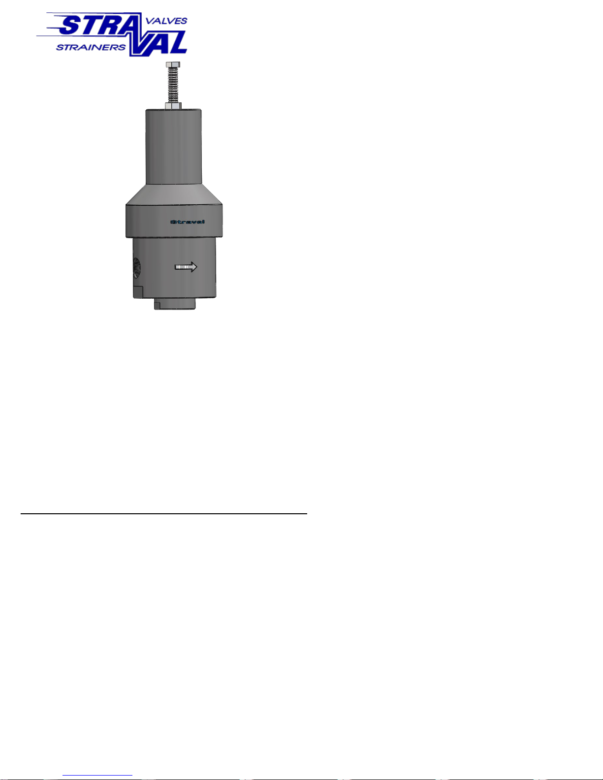
PRINCIPLE OF OPERATION:
Fluid passing through the valve enters the inlet port passing the
the valve seat formed by main valve, and finally through the
outlet port. Outlet pressure is sensed by the underside of the
diaphragm through a vertical port, which connects with the outlet port. Pressure regulation is achieved when a force balance is
maintained between the pressure acting on the underside of the
diaphragm and the spring force, which is adjusted to hold a particular outlet pressure. If the outlet pressure is below the set
point as preset by the adjusting spring, the spring force overcomes the pressure force acting on the underside of the diaphragm. This causes the main valve to open, thereby admitting
higher inlet pressure fluid to raise the outlet pressure until the
force balance is restored. As soon as the outlet pressure is restored, the main valve begins to close and to limit the amount
of higher inlet pressure fluid passing through the valve.
Never apply the valve on shut-off or dead ended service,
as the valve is not designed for this purpose. Always install a
relief valve on the outlet side of the regulator.
OPERATING INSTRUCTIONS
If the valve has not been ordered preset to a specific outlet
pressure, simply adjust the spring (5) compression by loosening the lock nut (2) and turn the adjusting screw (1) Clockwise to increase the spring compression. This will
increase the outlet pressure. Similarly, turning the screw
counterclockwise will reduce the spring compression and correspondingly reduce the outlet pressure.
OPERATING INSTRUCTIONS
MODEL PRS-09i-P
PLASTIC PRESSURE REDUCING
VALVE
DISASSEMBLY/ASSEMBLY INSTRUCTIONS
If the regulator fails to maintain the proper outlet pressure, there could be a number of probable causes as follows: Internal clogging of foreign objects or material,
sediment, etc. in the valve seat area, sensing port, diaphragm cavity and valve spring cavity which houses the
spring. If this condition appears frequently a strainer
installed at the inlet side of the valve is recommended.
If disassembly is required, make sure the valve piping is
not under pressure and sufficiently cooled off for operating personnel to handle. To disassemble the valve, it is
not necessary to remove the valve from the piping, although it may be more convenient to work on the valve at
a bench with a vise. Unscrew the spring chamber (3)
with a strap wrench.
If fluid is leaking from the adjusting screw, the diaphragm is suspect. Inspect the diaphragm (9), replace if
torn, abraded, or delaminated or otherwise damaged or
cut. Sealing area of the diaphragm should be free from
tears or cuts, otherwise external leakage will occur. Examine to see if there are signs the diaphragm pulled
away from the outer clamped seating area. If so, realign
diaphragm and make sure the spring chamber is tightened properly, and checked again for tightening after full
temperature is reached after installation. Also, check to
make sure the locknut (7) is tight which holds the diaphragm plates and main valve shaft together (6) & (8). A
spare diaphragm should always be kept on hand to keep
down time to a minimum.
Examine the main valve (6) and seat area for excessive
wear particularly in the valve seat area. Replace external
valve spring (5) if corroded or damaged.
Reassemble valve in the same sequence as disassembled
making sure the diaphragm lock nut (7) and spring
chamber (3) are tight so that no leakage can take place
in these areas. Tighten the diaphragm lock nut (6) snug
plus ¼ turn, and spring chamber hand tight plus ¼ turn
using a strap wrench (3). Also examine the O-ring seal
for the bottom plug to make sure it is not damaged or
shows signs of deterioration. Replace if necessary.
It is often easier to assemble the spring chamber assembly upside down by dropping the spring and spring hardware into the spring chamber. Then the body (11) subassembly with the main valve (6) and diaphragm (9) can
be positioned over the spring chamber (3) and threading
the assembly together until hand tight. Then the final
tightening with a strap wrench can be done with the
valve right side up.
Phone: 973-340-9955 Fax: 973-340-9933
http://www.straval.com Email: [email protected]
Page 2
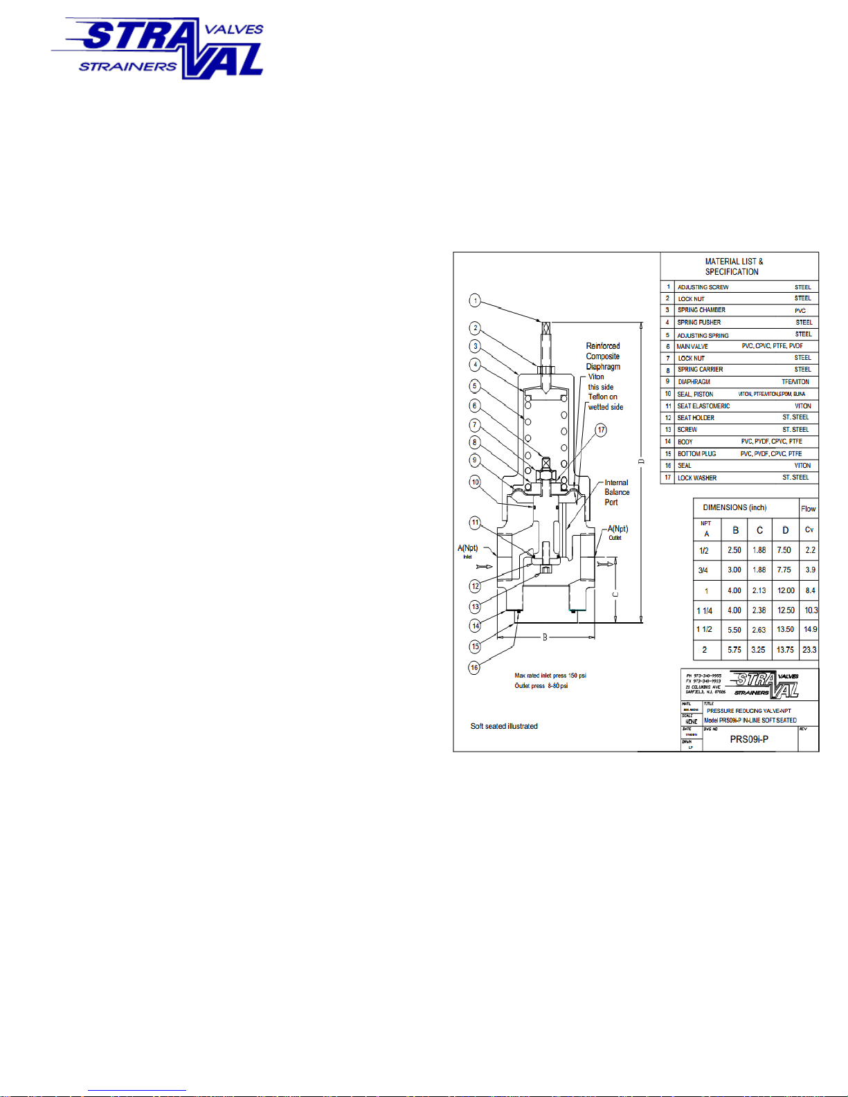
After the valve is properly assembled, reset the spring adjusting
screw (1) until the desired outlet pressure is achieved at the flow
range the valve will be operating. Then tighten the adjusting
screw lock nut (2). Note that some valves, depending on the
droop characteristic, may require readjustment of the spring setting if there are wide ranges in flows. Consult factory for application assistance if a different spring or if a different valve is required.
NOTE: When the outlet pressure must be maintained
at a specic value, and where excessive pressure may
damage equipment, a relief valve must be installed on
the outlet side of the regulator.
OPERATING INSTRUCTIONS
MODEL PRS-09i-P
PLASTIC PRESSURE REDUCING
VALVE
Phone: 973-340-9955 Fax: 973-340-9933
http://www.straval.com Email: [email protected]
 Loading...