

APPLICATIONS:
Valve should only be used for non-corrosive fluids, or where
the materials selected are compatible with the fluid and will
not cause corrosive buildup, which could keep the main
valve from opening. When liquids contain debris or other
solid matter, which might cause internal clogging or improper operation of the valve, a strainer with a fine wire mesh
should be installed before the inlet of the valve. In-line
strainer fittings or basket strainers can be purchased from
STRA-VAL to solve this problem. Do not use this valve as
a shutoff valve, even though the valve, when new, is able
to do so. In time as wear sets in, seat leakage may increase
and result in an objectionable pressure rise at zero flow. As
long as the flow through the valve is greater than the seat
leakage, the valve could still regulate.
PRINCIPLE OF OPERATION
Fluid passing through the valve enters through the inlet port
through the valve seat formed by the main valve and seat,
and finally through the outlet port. Outlet pressure is sensed
by the underside of the piston, which is able to move up and
down with changes in outlet pressure. Pressure regulation is
achieved when a force balance is maintained between the
pressure acting on the underside of the piston and the
spring force, which is adjusted to hold a particular outlet
pressure. If the outlet pressure is below the set point,
which is preset by the adjusting spring, the spring force
overcomes the pressure force acting on the underside of the
piston. This causes the main valve to open, thereby admitting higher inlet pressure fluid to raise the outlet pressure
until the force balance is restored. As soon as the outlet
pressure is restored, the main valve begins to close to limit
the amount of higher inlet pressure fluid passing through
the valve
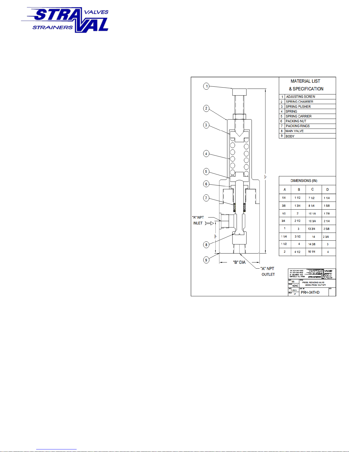
OPERATING INSTRUCTIONS
MODEL PRH-09THD
PRESSURE REDUCING VALVE
MAINTENANCE & REPAIR
When the valve is shipped from the factory it is usually ready for operation. On larger valves, all that may
be required is to install the adjusting screw if it is
strapped to the spring chamber and make a final pressure adjustment at the final operating conditions. This
step is not required if the valve is ordered preset for a
specific pressure setting and so marked
Check to make sure that the discharge piping is not
blocked off and that the valve does not operate
against a shut-off condition. Check to make sure there
is no visible leakage coming from the spring chamber.
This would occur if the packing nut is set too loose or
if the packing rings take a slight set. A simple adjustment of the packing nut by 1/6 or 1/4 turn is normally
sufficient. This would have to be done with the spring
chamber removed If after extensive use the valve begins to lose its ability to regulate, or if there is excessive seat leakage due to wear, which would cause an
excessive pressure rise on the outlet side of the
valve, or if there is external seal leakage, the valve
will require parts to be replaced and
the valve sent in for possible repair. Before removing
the valve from service Make sure that the valve is
isolated from the piping completely in order
avoid any personal injury
Usually, only the v-packing rings will require replacement. However, if there is excessive seat leakage,
then the main valve may also require replacement or
just a minor re-cutting of the seating surfaces. With
the valve removed from service, a quick test for mechanical operation is to see if the main valve is free
to move by hand. This should be done with the
spring chamber removed. If the main valve is not free
to move, the packing nut is either too tight or the
main valve is frozen in place or worn, and will therefore need to be disassembled.
DISASSEMBLY / ASSEMBLY INSTRUCTIONS
To disassemble the valve, it is best to remove the
valve from the piping, since it is more convenient to
work on the valve on a bench with a vise. Unscrew
the spring chamber with a wrench in the area provided
with wrench flats. With the spring chamber off, the
packing nut may be removed and the Teflon v-packing
rings extracted. Make sure the valve is not under
pressure if it is still in the line. Be sure not to damage
them as they perform a critical sealing function. If
they are damaged or worn they need to be replaced.
When reinstalling the v-packing rings, make sure that
they are properly installed as shown in the illustration
with the open part of the “v” facing the pressure side.
Phone: 973-340-9955 Fax: 973-340-9933
http://www.straval.com Email: sales@straval.com
The packing rings expand under pressure and therefore should
not be over tightened. If the packing rings are over tightened,
the valve will not be very responsive to pressure changes or not
even regulate at all. It is usually sufficient to make the packing
nut hand tight and add 1/4 to 1/2 turn with a wrench. Finally
when the valve is installed in the line without the spring chamber any additional tightening may be performed while under
pressure, if there still any leakage through the v-packing rings.
After this adjustment is performed, the spring chamber and
spring hardware may be installed. Next inspect the seat and
main valve in the area where sealing contact is made. It may
be necessary to just re-lap these parts with a fine grit lapping
compound such as A#600 grit. If there is more severe wear or
damage that can’t be corrected by lapping, then the parts need
to be replaced or re-machined making sure that the parts remain concentric. Also, inspect the main valve in the area where
the teflon-v-packing rings perform their sealing function.
If the area is not too severely worn, the surface may be repolished and restored to a smooth low friction surface finish. If
this area is very rough or worn, the valve will not regulate
properly and will stick because of excessive friction and wear. If
in doubt, replace the entire main valve from the factory. It is
generally recommended that the valve be overhauled by replacing the main valve, and v-packing rings, in order to restore the
valve in an as new condition. If the main valve is purchased
from the factory, it must be lapped into the body at final assembly for optimum regulating performance, particularly if the valve
is operating in a low flow mode where the valve travel is very
small and the clearance through the valve seat is very small.
After the valve is properly assembled, reset the adjusting screw
until the desired outlet pressure is achieved at the flow range
the valve will be operating, then tighten the adjusting screw lock
nut. Little or no adjustment is required to compensate for
changes in inlet pressure, as this valve is a balanced design.
OPERATING INSTRUCTIONS
MODEL PRH-09THD
PRESSURE REDUCING VALVE
OPERATING INSTRUCTIONS
Adjust the spring compression by loosening the lock nut and
turn the adjusting screw clockwise to increase the spring compression; this will increase the outlet pressure. Similarly, turning
the screw counterclockwise will reduce the spring compression
and correspondingly reduce the outlet pressure. A slow pressure
build up will take place if the outlet is completely blocked off
which may take place over a period of time depending on how
effective the valve seat is performing and the volume of the discharge piping. For this reason it is strongly recommended
that a relief valve be installed on the outlet side of the
valve to protect any equipment damage that may take place
because of this possible pressure build up in a shut off or
blocked discharge condition. If the regulator fails to maintain the
proper outlet pressure, there could be a number of probable
causes as follows: Packing nut may be over tightened, Internal
clogging of foreign objects or material, sediment, rust, etc. in
the valve seat area. If disassembly is required make sure the
valve piping is not under pressure and sufficiently cooled off for
operating personnel to handle. When a valve is ordered with
socket weld connections, the valve seat must be re-lapped by
the customer after the valve is welded to the piping. Every precaution should be made to minimize distortion due to excessive
heat during welding. Depending on the degree of distortion
caused by welding, it is recommended that lapping be performed
with several course grit grades first, and finally finishing with a
#600 or better yet a #800 grit to get the best seat finish.
Phone: 973-340-9955 Fax: 973-340-9933
http://www.straval.com Email: sales@straval.com
 Loading...