

Strautmann Verti-Mix 951-1651, Verti-Mix 1251-L, Verti-Mix 1501 D, Verti-Mix 951-L, Verti-Mix 3101 D Translation Of The Original Operating Instructions

Translation of the
Original Operating Instructions
Fodder mixing wagon
Verti-Mix 951-1651
Verti-Mix 951-L, 1251-L
Verti-Mix 1501 D-3101 D
65200921 0.000
05.16

Designation:
Fodder mixing wagon
Function:
Chopping, mixing, transport and discharge of all types of silage and normal
fodders used in keeping livestock
Model:
Verti-Mix
Verti-Mix L
Verti-Mix Double
Type:
951, 1251, 1451, 1651
951-L, 1251-L
1501 Double, 1801 Double, 2401 Double, 3101 Double
Serial number:
W09649000_0S38001-W09659000_0S38999
Trade name:
Fodder mixing wagon Verti-Mix
Fodder mixing wagon Verti-Mix L
Fodder mixing wagon Verti-Mix Double
Dipl.-Kfm. W. Strautmann
Managing Director
Dipl.-Wirt.-Ing. P. Strautmann
Managing Director
EU Declaration of Conformity
Manufacturer:
B. Strautmann & Söhne GmbH u. Co. KG
Bielefelder Str. 53
D-49196 Bad Laer
Legal person established within the EC and authorized to compile the technical documentation:
B. Strautmann & Söhne GmbH u. Co. KG
Bielefelder Str. 53
D-49196 Bad Laer
Description and identification of machine:
We hereby explicitly declare that the machine complies with all relevant provisions of the following
directives:
2006/42/EC:2006-05-17 EC machinery directive 2006/42/EC
2014/30/EU:2014-02-26 (Electromagnetic compatibility) Directive 2014/30/EU of the European
Parliament and the Council dated 26 February 2014 for harmonisation of
laws of the member states on the electromagnetic compatibility (revised
version)
Sources of the applied harmonized standards:
EN ISO 12100:2010 Safety of machinery - Basic concepts, general principles of design - Risk
assessment and risk reduction
EN ISO 13857:2008 Safety of machinery - Safety distances to prevent hazard areas from
EN ISO 4254-1:2013 Agricultural machinery - Safety - Part 1: General requirements
being reached by upper and lower limbs
EN 349:1993+A1:2008 Safety of machinery - Minimum distances to prevent limbs from being
crushed
EN ISO 4413:2010 Fluid power - General rules and safety requirements for hydraulic
systems and their components
EN 703:2004+A1:2009 Agricultural machinery - Silage loading, mixing and/or chopping and
Bad Laer, 04/01/2016
distributing machines - Safety

Identification data
Verti-Mix 951-1651, Verti-Mix 951-L, 1251-L, Verti-Mix 1501 D-3101 D 05.16
3
Operating instructions, spare parts lists and brochures are also
available in the Strautmann information library on the internet:
www.strautmann-infothek.de
Identification data
Please enter the machine’s identification data here. They are registered on the type plate.
Manufacturer: B. Strautmann & Söhne GmbH u. Co. KG
Vehicle/Machine ID number: _ _ _ _ _ _ _ _ _ _ _ _ _ _ _ _ _
Type:
Year of manufacture:
Manufacturer’s address
B. Strautmann & Söhne GmbH u. Co. KG
Bielefelder Straße 53
D-49196 Bad Laer
Phone: + 49 (0) 5424 802-0
Fax: + 49 (0) 5424 802-64
E-mail: info@strautmann.com
Spare parts order service
B. Strautmann & Söhne GmbH u. Co. KG
Bielefelder Straße 53
D-49196 Bad Laer
Phone: + 49 (0) 5424 802-30
Fax: + 49 (0) 5424 802-64
E-mail: parts@strautmann.com
Spare parts catalogue online: www.strautmann-elise.de
Please always refer to the vehicle/machine ID number of your machine when ordering spare parts.
Formal information about the operating instructions
Document number: 65200921 0.000
Date of compilation: 05.16
© Copyright B. Strautmann & Söhne GmbH u. Co. KG, 2016
All rights reserved.
Reproduction, even in excerpts, only allowed with the permission of B. Strautmann & Söhne GmbH u.
Co. KG.

Foreword
4
Verti-Mix 951-1651, Verti-Mix 951-L, 1251-L, Verti-Mix 1501 D-3101 D 05.16
Foreword
Dear customer,
You have decided in favour of a quality product from the large B. Strautmann & Söhne GmbH u. Co.
KG product range. We thank you for the confidence you have shown in us.
Upon receipt of the machine, please check for transport damage or missing parts! Check the delivered
machine for its completeness, including the ordered optional extras, by means of the delivery note.
Only immediate complaints will give reason to compensation!
Read and observe these operating instructions and any other included operating instructions for
individual machine components before the first start-up; in case of doubt, the details and information
contained in such sub-supplier documentation shall prevail! In particular observe the safety
instructions, thus being able to fully benefit from the advantages of your recently acquired machine.
Please make sure that all operators of the machine have read these operating instructions before
starting the machine.
The machines are available with various optional extras. Due to the individual equipment of your
machine, not all descriptions included in these operating instructions apply to your machine. Optional
extras are marked in these operating instructions and are available at extra cost.
In case of any inquiries or problems, please refer to these operating instructions or call us.
Regular service and maintenance and timely replacement of worn-out or damaged parts will result in a
longer service life of your machine.

Contents
Verti-Mix 951-1651, Verti-Mix 951-L, 1251-L, Verti-Mix 1501 D-3101 D 05.16
5
Contents
1 User information 10
1.1 Purpose of document 10
1.2 Keeping of operating instructions 10
1.3 Location details in the operating instructions 10
1.4 Applied modes of specification 10
1.5 Applied terms 11
1.6 Activity-related safety instructions and important information 11
1.6.1 Activity-related safety instructions 11
1.6.2 Important information 12
2 Product description 13
2.1 General overview of machine 13
2.2 Safety and protective devices 14
2.3 Supply lines between tractor and mchine 16
2.4 Traffic-related equipment 16
2.5 Type plate 17
2.6 Technical data 18
2.6.1 Verti-Mix 18
2.6.1.1 Dimensions of wagon 20
2.6.1.2 Tyre pressure 22
2.6.2 Verti-Mix L 22
2.6.2.1 Dimensions of wagon 23
2.6.2.2 Tyre pressure 24
2.6.3 Verti-Mix Double 24
2.6.3.1 Dimensions of wagon 25
2.6.3.2 Tyre pressure 27
2.7 Required tractor equipment 28
2.8 Drawbar 30
3 Safety instructions 31
3.1 Correct use 31
3.2 Safety-conscious working 31
3.3 Organisational measures 32
3.3.1 User’s obligation 32
3.3.2 Operator’s obligation 32
3.3.3 Qualification of operator 33
3.4 Product safety 33
3.4.1 Hazardous areas and dangerous spots 33
3.4.2 Safety-conscious operation of machine 34
3.4.3 Safety and protective devices 34
3.4.4 Structural alterations 34
3.4.5 Spare and wearing parts, auxiliary materials 35
3.4.6 Warranty and liability 35
3.5 Basic safety instructions 35
3.5.1 General safety and accident prevention instructions 35
3.5.2 Hydraulic system 38
3.5.3 Electrical system 39
3.5.4 Propeller shaft operation 39
3.5.5 Hitched machines 40
3.5.6 Brake system 40
3.5.7 Axles 41
3.5.8 Tyres 42
3.5.9 Fodder mixing wagon 42
3.5.10 Service and maintenance of machine 43
3.6 Warning and instruction signs 43

Contents
6
Verti-Mix 951-1651, Verti-Mix 951-L, 1251-L, Verti-Mix 1501 D-3101 D 05.16
3.6.1 Warning signs 44
3.6.2 Instruction signs 48
3.6.3 Placing of warning and instruction signs 49
3.7 Risks in case of non-observance of safety instructions and warning signs 52
4 Loading of machine 53
4.1 Verti-Mix 54
4.2 Verti-Mix L 54
4.3 Verti-Mix Double 55
5 Commissioning 56
5.1 Road traffic regulations 57
5.1.1 Road traffic regulations in Germany 57
5.2 Check tractor’s compatibility 58
5.2.1 Calculate actual values 58
5.2.2 Preconditions for the operation of tractors with rigid drawbar trailers 59
5.2.2.1 Combination options of coupling devices and drawgears 59
5.2.2.2 Calculate actual DC value for combination to be coupled 60
5.2.2.3 Calculate tractor’s admissible towing capacity 61
5.3 Secure tractor and machine against accidental starting and rolling 62
5.4 Drawbar 63
5.4.1 Adjust mounting height of drawbar 63
5.4.2 Couple drawbar 64
5.4.2.1 Bolt-type coupling 64
5.4.2.2 Tow-hook (hitch hook) and drawbar lug (hitch ring) 65
5.4.2.3 Draw pin (Piton-Fix) and drawbar lug (hitch ring) 65
5.4.2.4 Ball-type coupling and shell 65
5.4.3 Uncouple drawbar 66
5.4.3.1 Bolt-type coupling 66
5.4.3.2 Tow-hook (hitch hook) and drawbar lug (hitch ring) 67
5.4.3.3 Draw pin (Piton-Fix) and drawbar lug (hitch ring) 67
5.4.3.4 Ball-type coupling and shell 67
5.5 Propeller shaft 68
5.5.1 Adjust length of propeller shaft to tractor 69
5.5.2 Couple propeller shaft to the tractor 70
5.5.3 Uncouple propeller shaft from tractor 71
5.6 Supporting leg 71
5.6.1 Mechanical supporting leg 72
5.6.1.1 Lift mechanical supporting leg to transport position 72
5.6.1.2 Lower mechanical supporting leg to support position 72
5.6.2 Hydraulic supporting leg 73
5.6.2.1 Lift hydraulic supporting leg to transport position 73
5.6.2.2 Lower hydraulic supporting leg to support position 74
5.6.3 Fixed supporting leg with bottom hitch 74
5.7 Check machine for proper functioning 74
5.8 Hydraulic hose pipes 75
5.8.1 Connect hydraulic hose pipes 75
5.8.2 Disconnect hydraulic hose pipes 76
5.9 Brake system 76
5.9.1 Hydraulic service brake 77
5.9.1.1 Connect hydraulic brake system 78
5.9.1.2 Disconnect hydraulic brake system 79
5.9.2 Automatic reverse overrun brake system 79
5.9.2.1 Connect automatic reverse overrun brake system 80
5.9.2.2 Disconnect automatic reverse overrun brake system 80
5.9.3 Dual-line compressed-air brake system 81
5.9.3.1 Connect brake and feed line 82
5.9.3.2 Disconnect brake and feed line 83
5.9.3.3 Manoeuvre unhitched machine by means of a manoeuvring vehicle 84
5.9.4 Hydraulic service brake system 84

Contents
Verti-Mix 951-1651, Verti-Mix 951-L, 1251-L, Verti-Mix 1501 D-3101 D 05.16
7
5.9.4.1 Connect hydraulic brake system 85
5.9.4.2 Disconnect hydraulic brake system 85
5.9.5 Parking brake 85
5.10 Hitch and unhitch machine 86
5.10.1 Hitch machine 86
5.10.2 Unhitch machine 88
5.11 Container attachment 88
5.12 Set conveyor speed 89
5.12.1 Manual setting of conveyor speed 89
5.12.2 Set conveyor speed via control set 90
5.12.3 Set control dial range of E-control set 90
5.13 Mount control set on the tractor 91
5.13.1 Mount holder with pocket for Bowden cable control set 91
5.13.2 Mount E-control set on the tractor 92
5.14 Battery for weighing device 92
5.15 Set deflector plate 93
6 Operation 95
6.1 Direct tractor connection 95
6.2 Bowden cable control set 95
6.2.1 Possible symbols and their meaning 96
6.3 E-control set 99
6.3.1 Functions and their symbols 99
7 Use of machine 105
7.1 Fill fodder mixing wagon 107
7.1.1 Recommended filling order 109
7.2 Mix fodder components 110
7.2.1 Counter-cutters 110
7.3 Fodder discharge 111
7.3.1 Eliminate blockages 112
7.4 Working with the straw blower 113
7.4.1 Eliminate blockages 114
7.5 Working with the litter spreading drum 115
7.6 Driving mechanism with switchgear 117
7.6.1 Change gear level by means of switchgear 118
8 Transport journeys 119
8.1 Secure protective devices for transport journeys 120
8.2 Stop-cock at side discharge conveyor or conveyor extension 121
9 Service and maintenance of machine 122
9.1 Enter the mixing container 123
9.2 Cleaning of machine 126
9.3 Lubrication of machine 126
9.3.1 Lubrication plan 127
9.4 Preservation/Longer downtimes 128
9.5 Check/Top up/Change gear lubricant oil 128
9.5.1 Quantities when filled and change intervals 128
9.5.2 Admissible gear lubricant oils 129
9.5.3 Mixer gearbox 129
9.5.3.1 Check oil level 129
9.5.3.2 Change oil 130
9.5.4 Switchgear 132
9.5.4.1 Check oil level 132
9.5.4.2 Change oil 133
9.5.5 Spur gear for driving mechanism with on-board hydraulic system without
switchgear 133

Contents
8
Verti-Mix 951-1651, Verti-Mix 951-L, 1251-L, Verti-Mix 1501 D-3101 D 05.16
9.5.5.1 Check oil level 134
9.5.5.2 Change oil 134
9.6 On-board hydraulic system 134
9.6.1 Admissible hydraulic oils 135
9.6.2 Check oil level 135
9.6.3 Change oil 136
9.7 Replace shear bolts of shear bolt coupling 136
9.8 Auger position, Verti-Mix Double 137
9.9 Check / Adjust discharge door distance 137
9.10 Cutting knives of mixing auger(s) 138
9.10.1 Swivel / Replace cutting knives 139
9.10.2 Grind cutting knives 141
9.11 Crossover conveyor, discharge conveyor or conveyor extension 142
9.11.1 Check conveyor for visible defects 142
9.11.2 Adjust /Tighten conveyor 143
9.11.3 Clean driving rollers, carrying rollers and pulleys 143
9.12 C-conveyor 144
9.12.1 Check C-conveyor for visible defects 144
9.12.2 Tighten / Adjust C-conveyor 144
9.12.3 Clean C-conveyor 145
9.13 Replace Bowden cable of mechanical Bowden cable control unit 146
9.14 Replace remote control cable adapter 147
9.15 Hydraulic system 148
9.15.1 Depressurise hydraulic system 149
9.15.2 Hydraulic hose pipes 149
9.15.2.1 Marking and period of use of hydraulic hose pipes 149
9.15.2.2 Maintenance intervals 149
9.15.2.3 Inspection criteria for hydraulic hose pipes 150
9.15.2.4 Installation and removal of hydraulic hose pipes 150
9.16 Tyres 151
9.16.1 Check tyres 151
9.16.2 Change tyres 151
9.17 Brake system and chassis 152
9.17.1 Check/Clean in-line filters of compressed-air brake system 152
9.17.2 Check brake system for proper functioning. 153
9.17.3 Set compressed-air brake system 153
9.17.4 Drain compressed-air reservoir of compressed-air brake system 154
9.17.5 Set hydraulic brake system 155
9.17.6 Lubrication and maintenance plan – Chassis 155
9.17.7 Lubricate brake shaft bearing 157
9.17.8 Lubricate standard slack adjuster 158
9.17.9 Check clearance of wheel hub bearing 159
9.17.10 Check brake linings 159
9.18 Tightening torques 160
9.18.1 Tightening torques of wheel nuts 161
10 Remedy of malfunctions 162
10.1 Machine 162
10.2 Electrics 163
10.2.1 Emergency manual operation in case of failure of electrical system 163
10.3 Weighing device 164
11 Disassembly / Disposal 165
12 Circuit diagrams 166
12.1 Hydraulics 166
12.1.1 Without on-board hydraulic system 166
12.1.1.1 Bowden cable 166
12.1.1.2 E-control set and weighing and control set Multiscale 168

Contents
Verti-Mix 951-1651, Verti-Mix 951-L, 1251-L, Verti-Mix 1501 D-3101 D 05.16
9
12.1.2 With on-board hydraulic system 170
12.1.2.1 Without straw blower 170
12.1.2.2 With straw blower 172
12.2 Electronic system 174
12.2.1 E-control set 174
12.2.1.1 3-function control set 174
12.2.1.2 4-function control set 176
12.2.1.3 7-function control set 178
12.2.1.4 7-function control set with straw blower 180
12.2.2 Weighing and control set Multiscale 182
12.3 Weighing device 185
12.4 Connection of lighting system 185

User information
10
Verti-Mix 951-1651, Verti-Mix 951-L, 1251-L, Verti-Mix 1501 D-3101 D 05.16
1 User information
The chapter “User information“ provides information about how to use the operating instructions.
1.1 Purpose of document
These operating instructions:
describe the operation, service and maintenance of the machine,
provide important information about safety-conscious and efficient handling of the machine.
Please contact us for further inquiries.
1.2 Keeping of operating instructions
The operating instructions are part of the machine.
Therefore, always keep these operating instructions in the machine.
Hand these operating instructions over to the buyer when the machine is sold.
1.3 Location details in the operating instructions
Any directional data in these operating instructions refer to the direction of motion.
1.4 Applied modes of specification
Instructions and responses
Activities which have to be carried out in a predetermined order are specified as numbered
instructions. Always adhere to this order. In some cases, the response of the machine to the
respective instruction is marked by an arrow.
Example:
1. Instruction 1
→ Response of machine to instruction 1
2. Instruction 2
Lists
Lists without predetermined order are specified as lists with bullet points.
Example:
● Item 1
● Item 2
Position numbers in figures
Numbers in parentheses refer to position numbers in figures. The first number refers to the figure, the
second number to the position number in the figure.
Example: (Fig. 3/6) means figure 3, position 6.
Lines of position in figures
Starting from the position numbers, the lines of position refer to the respective components.

User information
Verti-Mix 951-1651, Verti-Mix 951-L, 1251-L, Verti-Mix 1501 D-3101 D 05.16
11
A line without an arrow
head means:
the component can be seen in the figure,
A line with an arrow head
means:
the component cannot be seen in the figure (e.g.
hidden by protective device).
Term
The term means
third person/party
… all other persons apart from the operator.
risk
… the source of a possible injury or damage to health.
manufacturer
… B. Strautmann & Söhne GmbH u. Co. KG.
machine
… Fodder mixing wagon Verti-Mix 951-1651, Verti-Mix 951-L, 1251-L,
Verti-Mix 1501 D-3101 D.
operating element
… the component of an operating element system which is directly
actuated by the operator, e. g. by pressing. An operating element may be
an adjusting lever, a key button, rotary switch, key etc.
DANGER
DANGER
marks a direct danger bearing a high risk, which will cause most
serious bodily injury (loss of limbs or long-term harm) or even
death if it is not prevented.
Non-observance of the safety instructions marked by “DANGER“
directly causes most serious bodily injury or even death.
References
An arrow head (►) in front of a sentence indicates a reference to further information elsewhere in the
operating instructions.
Example:
► Also observe the information in the chapter "Technical data", page 18.
1.5 Applied terms
1.6 Activity-related safety instructions and important information
Activity-related safety instructions and important information are included in the operating instructions.
Signal words and symbols help to identify activity-related safety instructions and important information
at a glance.
1.6.1 Activity-related safety instructions
Activity-related safety instructions:
warn about risks which may occur in a certain situation or in connection with a certain behaviour,
are directly mentioned in front of a hazardous activity in the individual chapters,
are marked by the triangular hazard symbol and a preceding signal word. The signal word refers
to the seriousness of the risk.

User information
12
Verti-Mix 951-1651, Verti-Mix 951-L, 1251-L, Verti-Mix 1501 D-3101 D 05.16
WARNING
WARNING
marks a possible danger bearing a moderate risk, which might
cause most serious bodily injury or even death if it is not
prevented.
Non-observance of the safety instructions marked by
“WARNING“ may cause most serious bodily injury or even
death.
CAUTION
CAUTION
marks a possible danger bearing a low risk, which might cause
light or moderate bodily injury or material damage if it is not
prevented.
Non-observance of the safety instructions marked by
"CAUTION" may cause light or moderate bodily injury or
material damage.
IMPORTANT
marks an obligation to behave in a particular manner or to act in
a certain way, in order to use the machine properly.
Non-observance of these instructions may cause malfunctions
of the machine or in its vicinity.
INFORMATION
marks user hints and particularly useful information.
This information will help you to use all functions of your
machine in the best possible way.
1.6.2 Important information
Important information:
provides details for proper use of the machine,
provides user hints for optimum use of the machine,
is marked by the following symbols.

Product description
Verti-Mix 951-1651, Verti-Mix 951-L, 1251-L, Verti-Mix 1501 D-3101 D 05.16
13
Fig. 1
(1) Drawbar
(2) Propeller shaft
(3) Propeller shaft holder
(4) Ladder, platform
(5) Supporting leg
(6) Counter-cutter
(7) Mixing container
(8) Parking brake
(9) Angular gear for mixing auger drive
(10) Shear bolt locking mechanism
(11) Braking axle
(12) Wheels
(13) Crossover conveyor *
(14) Protective device for crossover conveyor
(15) Hose holder for supply lines
(16) Control terminal of weighing device *
(17) Swivelling holder for control terminal of
weighing device
(18) Electro-hydraulic control block *
(19) Control set of electro-hydraulic E-control *
(20) Rear-view camera *
(21) Work light *
* Optional extra
2 Product description
Please read this chapter in the immediate vicinity of the machine if possible, thus acquainting yourself
with the machine in the best possible way.
The machines are available with various optional extras. Due to the individual equipment of your
machine, not all descriptions included in these operating instructions apply to your machine. Optional
extras are marked in these operating instructions and are available at extra cost.
2.1 General overview of machine

Product description
14
Verti-Mix 951-1651, Verti-Mix 951-L, 1251-L, Verti-Mix 1501 D-3101 D 05.16
Fig. 2
(1) Opening scale for dosage gate
(2) Pointer for opening width of dosage gate
(3) Chocks
(4) Compensating reservoir for gear lubricant
oil of angular gears
(5) Hydraulic or mechanical counter-cutter *
(6) Crossover conveyor *
(7) Protective device for crossover conveyor
(8) Spur gear for driving mechanism with on-
board hydraulic system *
(9) Inspection window *
(10) Feed funnel for mineral feed *
(11) Mixing auger(s), where applicable with
magnetic system *
WARNING
Risk to people of being crushed, drawn in and becoming entangled due to
unprotected powered driving elements during machine operation!
Start the machine only with the protective devices completely mounted.
It is not allowed to open protective devices:
when the machine is powered,
as long as the tractor engine is running with the propeller shaft coupled/the
hydraulic system connected,
if the ignition key is in the tractor and the tractor engine can be accidentally
started with the propeller shaft coupled/the hydraulic system connected,
if tractor and machine have not been secured against accidental rolling by
means of their respective parking brake and/or the chocks.
Close open protective devices before powering the machine.
* Optional extra
2.2 Safety and protective devices

Product description
Verti-Mix 951-1651, Verti-Mix 951-L, 1251-L, Verti-Mix 1501 D-3101 D 05.16
15
Fig. 3
(1) Propeller shaft holder
(2) Protective devices of propeller shaft
(3) Protective sleeve for drive shaft
(4) Hose holder for supply lines
(5) Ladder, platform
(6) Protective device for crossover conveyor at
the left-hand and right-hand front
(7) Protective device for side discharge at the
front (close-fitting, swivelling protective
cover), for protection against accidental
contact with the powered mixing auger
(8) Chocks
Fig. 4

Product description
16
Verti-Mix 951-1651, Verti-Mix 951-L, 1251-L, Verti-Mix 1501 D-3101 D 05.16
(1) Hydraulic connector "Flow line" red
(2) Hydraulic connector "Return line" blue
(3) Hydraulic connector for hydraulic service
brake
(4) Power supply for control system, 3-pole
(5) Lighting connector, 7-pole
(6) Compressed-air brake, feed line red
(only available with optional extra
equipment)
(7) Compressed-air brake, brake line yellow
(only available with optional extra
equipment)
(8) Hydraulic connector for hydraulic brake with
hydraulic clutch according to ISO 5676
(only with available optional extra
equipment, not allowed in Germany)
Fig. 5
Properly fix and check the traffic-related equipment for proper
functioning before travelling on public roads and paths.
Depending on the machine’s equipment, it is fitted with:
a lighting and identification system according to the national road traffic regulations,
a brake system, for details please refer to the chapter "Brake system", page 76.
Fig. 6
2.3 Supply lines between tractor and mchine
2.4 Traffic-related equipment

Product description
Verti-Mix 951-1651, Verti-Mix 951-L, 1251-L, Verti-Mix 1501 D-3101 D 05.16
17
(1) Speed sign
(2) Multi-function light with triangular reflector
(3) License plate
(4) Side reflectors
(5) Chocks
The complete marking is treated as a document and must not be
altered or made unrecognizable.
(1) Type plate with CE symbol
(2) Vehicle identification number (machine ID
number) (embossed into the frame)
Fig. 7
Information on the type plate:
(1) Manufacturer
(2) CE symbol
(3) Vehicle/Machine ID number
(4) Type
(5) Empty weight [kg]
(6) Gross vehicle weight rating [kg]
(7) Admissible tongue load/front axle load [kg]
(8) Admissible rear axle load [kg]
(9) Approval number
(10) Year of manufacture
(11) Rated speed [min-1]
(12) Admissible hydraulic pressure [bar]
(13) Maximum admissible speed [km/h]
Fig. 8
2.5 Type plate

Product description
18
Verti-Mix 951-1651, Verti-Mix 951-L, 1251-L, Verti-Mix 1501 D-3101 D 05.16
Type
Verti-Mix
Unit
951
1251
1451
1651
Usable mixing capacity*
(Loading capacity)
m3
7.5
8.5
9.5
10.0
11.5
12.5
13.5
15.0
--
13.5
15.0
16.5
Extension height
m
--
0.18
0.36
--
0.18
0.36
--
0.18
--
--
0.18
0.36
Gross vehicle weight rating
when equipped with:
Hydraulic service brake
kg
7000
9000
11400
11400
Overrun brake
kg
7000
8000
--
--
Dual-line service brake
system
kg
7000
9000
11400
11400
Admissible axle load when
equipped with:
Hydraulic service brake
kg
6000
7800
10000
10000
Overrun brake
kg
6000
7000
--
--
Dual-line service brake
system
kg
6000
7800
10000
10000
Admissible tongue load
Hydraulic service brake/
Dual-line service brake
system
kg
1000
1200
1400
1400
Overrun brake
kg
1000
1000
--
--
Empty weight (approx.):
with crossover conveyor
kg
3260
3860
4840
4900
Minimum power required:
without switchgear, 26
min-1
kW
26
28
31
37
38
41
53
58
--
--
--
--
with switchgear, 14.4 / 26
min-1
kW
19
21
22
26
28
29
33
36
--
--
--
--
without switchgear, 30
min-1
kW
32
35
37
49
51
54
63
69
--
65
71
78
with switchgear, 16.7 / 30
min-1
kW
23
25
27
35
37
41
45
49
--
40
44
48
without switchgear, 23
min-1
kW
--
--
--
--
--
--
--
--
--
54
59
65
with switchgear, 12.8 / 23
min-1
kW
--
--
--
--
--
--
--
--
--
33
36
40
Maximum operating pressure
bar
210
Oil flow rate
l/min
25 – 45
Power supply weighing device /
volt
12 VDC
2.6 Technical data
2.6.1 Verti-Mix

Product description
Verti-Mix 951-1651, Verti-Mix 951-L, 1251-L, Verti-Mix 1501 D-3101 D 05.16
19
Type
Verti-Mix
Unit
951
1251
1451
1651
Usable mixing capacity*
(Loading capacity)
m3
7.5
8.5
9.5
10.0
11.5
12.5
13.5
15.0
--
13.5
15.0
16.5
Extension height
m
--
0.18
0.36
--
0.18
0.36
--
0.18
--
--
0.18
0.36
lighting system / electrohydraulic control set
P.t.o. speed
min-1
540
Sound pressure level
dB(A)
≤84
* Actually usable mixing capacity, mixing augers having been deducted from the
capacity
Tab. 1
Figures, technical data and weights may change due to technical development and are not binding for
delivery.
The sound pressure level mainly depends on the tractor used.

Product description
20
Verti-Mix 951-1651, Verti-Mix 951-L, 1251-L, Verti-Mix 1501 D-3101 D 05.16
Fig. 9
2.6.1.1 Dimensions of wagon

Product description
Verti-Mix 951-1651, Verti-Mix 951-L, 1251-L, Verti-Mix 1501 D-3101 D 05.16
21
Type
Verti-Mix
Unit
951
1251
1451
1651
Extension height
- 0.18
0.36
-
0.18
0.36
-
0.18 - -
0.18
0.36
Length:
A = with front crossover
conveyor
m
5.30
5.50
5.75
5.75
B = with rear crossover
conveyor*
m
4.90
5.04
5.17
5.17
C = with side discharge /
without crossover conveyor
m
4.65
4.87
5.10
5.10
Width:
D = with crossover conveyor
m
2.16
2.28
2.42
2.42
E = with right-hand or left-
hand side discharge
m
2.26
2.38
2.52
2.52
E = with side discharge on
both sides
m
2.36
2.48
2.62
2.62
Height incl. tyres:
F = with 10.0/75-15.3 (18 PR)
m
2.31
2.49
2.67
--
--
--
F = with 30 x 11.5 -14.5
m
2.30
2.48
2.66
2.59
2.77
2.95
--
--
F = with 250/70-15.5 (18 PR)
Reduction of load capacity:
m
2.32
2.5
2.68
2.61
2.79
--
--
--
kg
--
8500
F = with 400/60-15.5 (14 PR)
m
2.43
2.61
2.79
--
--
--
F = with 400/60-15.5 (18 PR)
Reduction of load capacity:
m
--
2.72
2.9
3.08
3.05
--
--
3.05
--
--
kg 9660
9660
F = with 8.15-15 (14 PR)
double
m
--
2.58
2.76
--
2.94
3.12
--
2.94
3.12
3.30
F = with 19.0/45 - 17
Reduction of load capacity:
m
--
2.72
2.90
--
--
--
kg
8320
--
F = with 215/75R17.5 (133)
double
m
--
--
2.97
3.15
-
2.97
3.15
3.33
F = with 435/50 R 19.5,
retreated
m
--
2.8
2.98
3.16
3.14
3.32
-
3.14
3.32
3.50
G = Track
m
1.51
1.63
1.74
1.74
H = Outside wheel width incl.
standard tyres:
m
1.78
(10.0/75-
15.3)
2.04
(400/60-15.5)
2.23
(8.15-15)
2.23
(8.15-15)
J = Container length
m
3.03
3.33
3.67
3.67
Discharge height
m
0.75
0.87
0.74
0.74
* + 0.13 m with lighting
Tab. 2
Figures, technical data and weights may change due to technical development and are not binding for
delivery.

Product description
22
Verti-Mix 951-1651, Verti-Mix 951-L, 1251-L, Verti-Mix 1501 D-3101 D 05.16
Type
Verti-Mix
Tyres
Unit
951
1251
1451
1651
10.0/75-15.3 (18 PR)
bar
7.0
--
--
--
30 x 11.5 – 14.5
bar
8.0
8.0
--
--
250/70-15 (18 PR)
bar
9.5
9.5
--
--
400/60-15.5 (14 PR)
bar
5.0
--
--
--
400/60-15.5 (18 PR)
bar
--
6.0
6.0
6.0
8.15-15 (14 PR) double
bar
--
9.0
9.0
9.0
19.0/45-17
bar
--
4.0
--
--
215/75R17.5 (133) double
bar
--
--
9.5
9.5
435/50 R 19.5
bar
--
9.0
9.0
9.0
Tab. 3
Type Verti-Mix L
Unit
951-L
1251-L
Usable mixing capacity* (Loading capacity)
m3
7.5
8.5
9.5
10.0
11.0
12.5
Extension height
m
--
0.18
0.36
--
0.18
0.36
Gross vehicle weight rating when equipped with:
Hydraulic service brake
kg
7760
8700
Admissible axle load when equipped with:
Hydraulic service brake
kg
5260
6200
Admissible tongue load
kg
2500
2500
Empty weight (approx.):
kg
with side discharge on both sides
kg
3250
3820
Minimum power required:
without switchgear, 26 min-1
kW
26
28
31
37
38
41
with switchgear, 14.4 / 26 min-1
kW
19
21
22
26
28
29
without switchgear, 30 min-1
kW
32
35
37
49
51
54
with switchgear, 20 / 30 min-1
kW
23
25
27
35
37
41
Maximum operating pressure
bar
210
Oil flow rate
l/min
25 – 45
Power supply weighing device / lighting system / electrohydraulic control set
volt
12 VDC
P.t.o. speed
min-1
540
Sound pressure level
dB(A)
≤84
* Actually usable mixing capacity, mixing augers having been deducted from the capacity
Tab. 4
2.6.1.2 Tyre pressure
2.6.2 Verti-Mix L

Product description
Verti-Mix 951-1651, Verti-Mix 951-L, 1251-L, Verti-Mix 1501 D-3101 D 05.16
23
Fig. 10
Type
Verti-Mix L
Unit
951-L
1251-L
Extension height
m
-
0.18
0.36
-
0.18
0.36
Length:
A = with side discharge
m
4.85
4.85
Width:
B = with right-hand or left-hand side
discharge
m
2.26
2.38
B = with side discharge on both sides
m
2.36
2.48
Height incl. tyres*:
C = with 250/70-15.5 (18 PR)
m
2.10
2.28
2.46
2.39
2.57
2.75
C = with 400/60-15.5 (18 PR)
m
2.16
2.34
2.52
2.45
2.63
2.81
C = with 30 x 11.5-14.5
m
2.10
2.28
2.46
2.39
2.57
2.75
D = Track
m
1.65
1.65
E = Outside wheel width incl. standard tyres:
m
1.90
1.90
F = Container length
m
3.03
3.33
Discharge height*
m
0.54
0.54
*a change in height of + 6 cm (high version) or - 6 cm (low version) can be achieved via a change of
the axle position. In the factory setting, the axle is mounted in middle position (dimensions as
described above).
Tab. 5
Figures, technical data and weights may change due to technical development and are not binding for
delivery.
The sound pressure level mainly depends on the tractor used.
2.6.2.1 Dimensions of wagon
Figures, technical data and weights may change due to technical development and are not binding for
delivery.

Product description
24
Verti-Mix 951-1651, Verti-Mix 951-L, 1251-L, Verti-Mix 1501 D-3101 D 05.16
Type Verti-Mix L
Tyres
Unit
951-L
1251-L
250/70-15 (18 PR)
bar
9.5
9.5
400/60-15.5 (18 PR)
bar
6.0
6.0
30 x 11.5-14.5
bar
8.0
8.0
Tab. 6
Type
Verti-Mix Double
Unit
1501 D
1801 D
2401 D
3101 D
Usable mixing capacity* (Loading
capacity)
m3
12
13.5
15
14
16
18
19
21
24
25
28
31
Extension height
m
-
0.18
0.36
-
0.18
0.36
-
0.18
0.36
-
0.18
0.36
Gross vehicle weight rating when
equipped with:
Single axle
kg
11800
11800
11800
--
Tandem axle
kg
--
12800
17800
18000
Admissible axle load when
equipped with:
Single axle
kg
10000
10000
10000
--
Tandem axle
kg
--
11000
16000
16000
Admissible tongue load
kg
1800
1800
1800
2000
Empty weight with crossover
conveyor (approx.):
Single axle
kg
5550
6150
7350
--
Tandem axle
kg
--
6550
7800
9675
Minimum power required:
without switchgear, 26 min-1
kW
62
68
75
66
73
80 - - - - - -
without switchgear, 30 min-1
kW
73
80
88
84
91
98 - - - - - -
with switchgear, 14.4 / 26
min-1
kW
38
42
46
40
45
49
60
64
67 - -
-
with switchgear, 16.7 / 30
min-1
kW
45
49
54
52
56
60
73
78
82
87
92
98
with switchgear, 12.8 / 23
min-1
kW
- - - - - - - - -
74
78
82
Maximum operating pressure
bar
210
Oil flow rate
l/min
25 - 45
Power supply weighing device /
lighting system / electro-hydraulic
control set
volt
12 VDC
2.6.2.2 Tyre pressure
2.6.3 Verti-Mix Double

Product description
Verti-Mix 951-1651, Verti-Mix 951-L, 1251-L, Verti-Mix 1501 D-3101 D 05.16
25
Type
Verti-Mix Double
Unit
1501 D
1801 D
2401 D
3101 D
P.t.o. speed
min-1
540
Sound pressure level
dB(A)
≤85
* Actually usable mixing capacity, mixing augers having been deducted from the capacity
Tab. 7
Fig. 11
Figures, technical data and weights may change due to technical development and are not binding for
delivery.
The sound pressure level mainly depends on the tractor used.
2.6.3.1 Dimensions of wagon
Product description
26
Verti-Mix 951-1651, Verti-Mix 951-L, 1251-L, Verti-Mix 1501 D-3101 D 05.16
Type
Verti-Mix Double
Unit
1501 D
1801 D
2401 D
3101 D
Extension height
m
-
0.18
0.36
-
0.18
0.36
-
0.18
0.36
-
0.18
0.36
Length:
A = with front
crossover conveyor
m
7.01
7.40
7.76
8.13
B = with rear
crossover
conveyor*
m
6.61
6.98
7.27
7.55
C = without
crossover conveyor
m
6.34
6.71
7.06
7.44
Width:
D = with crossover
conveyor
m
1.96
2.16
2.28
2.42
E = with right-hand
or left-hand side
discharge
m
2.06
2.26
2.38
2.52
E = with side
discharge on both
sides
m
2.16
2.36
2.48
2.62
Height incl. tyres (single
axle):
F = with 8.15- 15
(14 PR) double
Middle axle position
m
m
2.30
2.28
2.48
2.46
2.66
2.64
2.34
--
2.52
--
2.70
--
2.62
--
2.80
--
2.98
--
--
--
F = with 215/75-
17.5 double
Middle axle position
m
m
2.36
2.35
2.54
2.53
2.72
2.71
2.37
--
2.55
--
2.73
--
2.66
--
2.84
--
3.02
--
--
--
F = with
235/75R17.5
double
m
--
--
2.66
2.84
3.02
--
F = with
455/45R22.5
m
--
--
2.85
3.03
3.21
F = with
435/50R19.5
Middle axle position
Reduction of load
capacity:
m
m
2.51
2.49
2.69
2.67
2.87
2.85
2.52
--
2.70
--
2.88
--
2.80
2.98
--
3.16
-kg
--
--
12100
F = with 400/60-
15.5
Middle axle position
Reduction of load
capacity:
m
m
2.43
2.38
2.61
2.56
2.79
2.74
--
--
kg

Product description
Verti-Mix 951-1651, Verti-Mix 951-L, 1251-L, Verti-Mix 1501 D-3101 D 05.16
27
Type
Verti-Mix Double
Unit
1501 D
1801 D
2401 D
3101 D
Extension height
m
-
0.18
0.36
-
0.18
0.36
-
0.18
0.36
-
0.18
0.36
Height incl. tyres
(Tandem axle):
F = with 10.0/75-
15.3
m
2.38
2.56
2.74
F = with 400/60-
15.5
Increase of load
capacity:
m
2.51
2.69
2.87
2.8
2.98
3.16
kg
12800
17800
--
F = with
435/50R19.5, track
1930
m
--
--
2.87
3.05
3.23
3.21
3.39
3.57
Increase of load
capacity:
kg
--
--
17800
--
F = with 435/50R19.5,
track 1720
m
--
2.56
2.74
2.92
2.84
3.02
3.20
3.21
3.39
3.57
Increase of load
capacity:
kg
--
12800
17800
--
G = Track
m
1.52
1.52
1.74
1.94
H = Outside wheel width
incl. standard tyres:
m
2.03
2.03
2.03
J = Container length
m
4.84
5.17
5.59
6.07
Discharge height with
crossover conveyor
m
0.79
0.81
0.81
1.03
* + 0.13 m with lighting
Tab. 8
Type
Verti-Mix Double
Tyres
Unit
1501 D
1801 D
2401 D
3101 D
Single axle
8.15-15 (14 PR) double
bar
9.0
9.0
9.0
--
215/75R17.5 (133) double
bar
9.5
9.5
9.5
--
235/75R17.5 double
bar
--
--
9.5
--
435/50 R 19.5
bar
9.0
--
--
--
400/60-15.5 (18 PR)
bar
6.0
--
--
--
455/45R22.5
bar
--
--
9.0
--
Figures, technical data and weights may change due to technical development and are not binding for
delivery.
2.6.3.2 Tyre pressure

Product description
28
Verti-Mix 951-1651, Verti-Mix 951-L, 1251-L, Verti-Mix 1501 D-3101 D 05.16
Type
Verti-Mix Double
Tyres
Unit
1501 D
1801 D
2401 D
3101 D
Tandem axle
10.0/75-15.3 (18 PR)
bar
--
7.0
--
--
400/60-15.5 (18 PR)
bar
--
6.0
6.0
--
435/50 R 19.5
bar
--
--
9.0
9.0
Tab. 9
Battery voltage:
12 V (volt)
Socket for lighting:
7-pole
Socket for control set:
3-pole (DIN 9680). The feed line of the 3-pole socket should
have a minimum cable cross section of 4 mm².
Check the compatibility of the hydraulic oils before connecting
the machine to the hydraulic system of your tractor. For details
about checking the compatibility of the hydraulic oils, contact
your agricultural machinery dealer if necessary.
Do not mix mineral oils with bio oils.
Maximum operating pressure:
210 bar
Delivery rate of hydraulic pump
min. 25 l/min and max. 45 l/min at 180 bar
Hydraulic oil of machine:
ATF Hydraulic oil
Depending on their function, the hydraulic components can be
connected to:
a double-acting control device,
a single-acting control device and a depressurised return line
leading directly into the hydraulic oil tank of the tractor.
Given a free choice, we recommend a single-acting control device
and a depressurised return line. The hydraulic oil flows back into the
hydraulic oil tank of the tractor through the free return line with a low
back pressure. Thus, a free return line reduces heating-up of the
hydraulic oil.
2.7 Required tractor equipment
The employed tractor must meet the following requirements, in order to ensure correct use of the
machine:
Tractor engine output
For the necessary power required, please refer to chapter "Technical data", page 18.
Electrical system
Hydraulics
Product description
Verti-Mix 951-1651, Verti-Mix 951-L, 1251-L, Verti-Mix 1501 D-3101 D 05.16
29
Hydraulic component:
Required control devices on the tractor:
Discharge door:
1 double-acting control device
Hydraulic supporting leg:
1 double-acting control device
Hydraulic counter-cutters:
1 double-acting control device
Hydraulic motor for
crossover conveyor:
Optional:
1 double-acting control device or
1 single-acting control device and
1 pressure-less return line (max. back pressure in return line
5 bar)
Side discharge conveyor:
1 double-acting control device (extend and retract)
Hydraulic motor for side
discharge conveyor:
Optional:
1 double-acting control device or
1 single-acting control device and
1 pressure-less return line (max. back pressure in return line
5 bar)
Conveyor extension:
1 double-acting control device (extend and retract)
Tab. 10
Required control devices on
the tractor:
Optional:
1 double-acting control device or
1 single-acting control device and
1 pressure-less return line (max. back pressure in return line
5 bar)
Tab. 11
Hydraulic service brake up to 6
km/h (not licensed for public
road traffic):
1 single-acting control device
Dual-line service brake system:
Dual-line compressed-air brake system including:
1 hose coupling (red) for the feed line
1 hose coupling (yellow) for the brake line
Hydraulic service brake (only
available for export):
1 hydraulic clutch according to ISO 5676 (100 bar)
Tab. 12
The used tractor must be equipped with mirrors such that the hazardous areas on both sides of the
machine are clearly visible from the tractor's seat.
Operation via direct tractor connection
Operation via Bowden cable or electro-hydraulic E-control
Optional extra
Brake system
Mirrors

Product description
30
Verti-Mix 951-1651, Verti-Mix 951-L, 1251-L, Verti-Mix 1501 D-3101 D 05.16
The machine is equipped with a vertically adjustable drawbar for:
Top linkage with flanged drawbar lug 40 mm according to DIN 74054-1/2 / ISO 8755,
Top linkage with drawbar lug 40 mm according to DIN 74054-1/2 / ISO 8755 with automatic
reverse system (25 km/h) (only Verti-Mix 951, 1251),
Top linkage with flanged and cranked drawbar lug 40 mm
Top linkage with coupling head type 80
Bottom linkage with coupling head type 80
Bottom linkage with flanged drawbar lug type 3394 and fixed supporting leg,
Bottom linkage with flanged drawbar lug 50 mm according to DIN 74053-1 / ISO 1102.
The drawbar (1) can be screwed on within the
adjusting range of the positioning holes (2) at
different levels compared to the chassis (3)
(Fig. 12).
This allows optimum adjustment of the drawbar
lug (4) to the respective height of the coupling
device of the different tractors.
The drawbar lug (4) is coupled by means of an
appropriate bolt-type coupling.
Fig. 12
2.8 Drawbar
► See also chapter "Adjust mounting height of drawbar ", page 63!

Safety instructions
Verti-Mix 951-1651, Verti-Mix 951-L, 1251-L, Verti-Mix 1501 D-3101 D 05.16
31
Observe all safety instructions included in these operating
instructions!
Most accidents are caused by non-observance of simplest safety
rules.
By observing all safety instructions included in these operating
instructions, you help to prevent accidents.
The fodder mixing wagons of the Verti-Mix series:
are designed for chopping, homogeneous mixing, transport and discharge all types of silage and
normal fodders used in keeping livestock if the dry substance content of the total mixture is more
than 30 % at any time of the mixing process,
must not be charged otherwise than by means of:
a tractor equipped with a front loader,
a yard or wheeled loader,
a telescopic loader,
the provided feeding aids such as mineral feed funnel, etc.
directly from the pipe or conveying device for concentrated feed, mineral feed etc.
3 Safety instructions
This chapter contains important information for the user and the operator on how to operate the
machine in a safety-conscious and trouble-free way.
3.1 Correct use
The following is also part of the correct use:
the observance of all instructions contained herein,
the observance of the specified service and maintenance work on the machine,
the exclusive use of original spare parts.
Any use beyond this is prohibited and will be regarded as incorrect.
For any damage resulting from incorrect use:
the user will be solely responsible,
the manufacturer will not assume any liability.
3.2 Safety-conscious working
The machine complies with the safety-related requirements and state of the art. When using the
machine, risks and impairments might yet arise:
● for life and limb of the operator or third parties,
● for the machine itself,
● to other material assets.
For the safety-conscious operation of the machine, please observe:
● these operating instructions, in particular:

Safety instructions
32
Verti-Mix 951-1651, Verti-Mix 951-L, 1251-L, Verti-Mix 1501 D-3101 D 05.16
WARNING
Risk of being crushed, cut, becoming entangled, being drawn in
or risk of impact if the tractor and the machine are not in
adequate roadworthy and reliable condition!
Check tractor and machine for their road and operational safety
before each startup.
The operating instructions:
must always be kept at the machine's place of operation,
must always be easily accessible for operating and maintenance
staff.
● the basic safety instructions, the activity-related safety instructions and the instructions
what to do,
● the instructions regarding correct use.
● the warning signs on the machine,
● the general national occupational safety, accident prevention and environmental protection
rules,
● the national road traffic regulations when carrying out transport journeys.
Only operate the machine in perfect safety-related condition.
3.3 Organisational measures
3.3.1 User’s obligation
The user is obliged:
to observe the general national occupational safety, accident prevention and environmental
protection rules,
to exclusively have staff operating the machine who:
know the basic occupational safety and accident prevention regulations,
have been instructed how to operate the machine,
have read and understood these operating instructions.
to keep all warning signs attached to the machine in legible condition,
to replace any damaged warning signs,
to provide the necessary personal protective equipment such as protective goggles, work gloves
according to DIN EN 388, safety footwear, protective clothing, skin protectant, etc.
3.3.2 Operator’s obligation
Any members of staff charged to operate the machine are obliged:
to acquaint themselves with the machine before starting operation,
to acquaint themselves with the following regulations and to observe them during work:
the general national occupational safety, accident prevention and environmental protection
rules,
the chapter "Basic safety instructions“, page 35,
the chapter „Warning and instruction signs“, page 43, and the warning signs when operating
the machine,

Safety instructions
Verti-Mix 951-1651, Verti-Mix 951-L, 1251-L, Verti-Mix 1501 D-3101 D 05.16
33
Only trained and instructed staff is allowed to operate the machine.
The user must clearly define the responsibilities of the members of
staff for operation, service and maintenance.
A person to be trained must be supervised when operating the
machine.
The operator is only allowed to carry out such work as specified in
these operating instructions which is not marked as "Shop work".
Only authorised workshops are allowed to carry out work on the
machine which requires special expert knowledge. Authorised
workshops have qualified staff and adequate means (tools, lifting and
supporting equipment) at their disposal to carry out this work properly.
This applies to any work:
which is not mentioned in these operating instructions,
which is marked as "Shop work" in these operating instructions.
People are not allowed in the hazardous area:
if the tractor engine is running with the propeller shaft coupled/
the hydraulic/electronic system connected,
if tractor and machine are not secured against accidental
starting and rolling.
Only if no people are within the hazardous area of the machine, is the
operator allowed to:
move the machine,
set movable machine parts from transport to working position
and from working to transport position,
power working tools.
the chapters of these operating instructions which are important for the tasks assigned to
them.
If the operator notices that a device is not in a sound safety-related condition, the operator shall be
obliged to immediately eliminate this defect. If this is not part of the operator’s scope of tasks or he/she
lacks adequate expert knowledge, the operator shall be obliged to report this defect to his/her superior
or to the user.
3.3.3 Qualification of operator
3.4 Product safety
3.4.1 Hazardous areas and dangerous spots
The hazardous area is the area within and/or in the vicinity of a machine, in which the safety or health
of people might be impaired.
Within the hazardous area, risks occur at dangerous spots which cannot be completely eliminated due
to the operational safety of the machine. The risks exist permanently or may occur unexpectedly.
Dangerous spots are marked by warning signs attached to the machine, which warn about existing
residual risks.

Safety instructions
34
Verti-Mix 951-1651, Verti-Mix 951-L, 1251-L, Verti-Mix 1501 D-3101 D 05.16
Dangerous spots exist:
within the drawbar area between tractor and machine,
within the area of the powered propeller shaft,
within the area of the discharge openings,
within the area of the powered discharge conveyor, crossover conveyor or conveyor extension,
in the mixing container with the machine powered or not powered,
around the discharge pipe and in ejection direction in case of machines equipped with straw
blower.
In these operating instructions, activity-related safety instructions mark the existing residual risks.
Risks may arise:
due to work-related movements of the machine and its working tools,
due to substances or foreign objects blown out of the machine,
due to accidental lowering of the lifted machine/of lifted machine parts,
due to accidental starting and rolling of the machine / of tractor and machine.
3.4.2 Safety-conscious operation of machine
The machine is only allowed to be operated from the driver’s seat of the tractor, provided that no
people are within the machine’s hazardous area. Observe the information in the chapter "Hazardous
areas and dangerous spots", page 33.
3.4.3 Safety and protective devices
Only operate the machine when all safety and protective devices are properly fixed and in fully
operable condition.
Defective or removed safety and protective devices might cause dangerous situations.
Check all safety and protective devices for visible damage and functional ability before starting
the machine.
3.4.4 Structural alterations
Vehicles provided with an official operating license or vehicle-linked devices and equipment
provided with an official operating license or a road traffic license according to the road traffic
regulations must be in the condition specified by that license.
You are only allowed to carry out structural alterations, extensions or modifications on the
machine with the prior written consent of the manufacturer.
In case of non-authorized structural alterations, extensions or modifications:
the declaration of conformity and the CE symbol of the machine will become invalid,
the operating license according to national and international regulations will become invalid.
Exclusively use original parts or modification and accessory parts approved by the manufacturer
such that:
the declaration of conformity and the CE symbol of the machine will remain unaffected,
the operating license according to national and international regulations will remain
unaffected,
perfect functioning of the machine will be ensured.
The manufacturer will not assume any liability for damage resulting from:

Safety instructions
Verti-Mix 951-1651, Verti-Mix 951-L, 1251-L, Verti-Mix 1501 D-3101 D 05.16
35
unauthorized alterations of the machine,
non-approved modification and accessory parts,
welding and drilling work on load-bearing parts of the machine.
3.4.5 Spare and wearing parts, auxiliary materials
Immediately replace machine parts which are not in perfect condition.
Exclusively use original parts of the manufacturer or parts approved by the manufacturer such that the
operating license according to national and international regulations will remain unaffected. If spare
and wearing parts produced by third-party manufacturers are used, their stress-related and safetyconscious design and production will not be ensured.
The manufacturer will not assume any liability for damage resulting from the use of non-approved
spare and wearing parts or auxiliary materials.
3.4.6 Warranty and liability
As a basic principle, our "General Sales Terms and Delivery Conditions" shall apply. They have been
handed over to the user upon conclusion of contract at the latest.
Any warranty and liability claims in case of personal injury and material damage will be excluded if
they are due to one or several of the following reasons:
improper use of the machine,
improper assembly, commissioning, operation and maintenance of the machine,
operation of the machine, the safety devices being defective or the safety and protective devices
having not been properly installed or being not serviceable,
non-observance of the instructions included in the operating instructions referring to
commissioning, operation and maintenance,
unauthorized structural alterations on the machine,
insufficient inspection of machine parts which are subject to wear,
improperly effected repairs,
disasters due to foreign objects and force majeure.
3.5 Basic safety instructions
► See also chapter "Secure tractor and machine against accidental starting and rolling", page 62!
► See also chapter "Enter the mixing container ", page 123!
Basic safety instructions:
shall, as a basic principle, apply to the safe operation of the machine,
are summarized in the subsections below.
3.5.1 General safety and accident prevention instructions
Observe the general national safety and accident prevention regulations in addition to the safety
instructions included in this chapter!
Observe the warning and instruction signs attached to the machine. They provide important
information for the safe and trouble-free operation of the machine!
Observe the activity-related safety instructions included in the other chapters in addition to the
basic safety instructions included in this chapter!

Safety instructions
36
Verti-Mix 951-1651, Verti-Mix 951-L, 1251-L, Verti-Mix 1501 D-3101 D 05.16
Wear your personal protective equipment when carrying out work on the machine!
Make sure that people leave the immediate vicinity of the machine before moving or starting the
machine! Particularly be aware of children!
Never carry passengers, animals or objects on the machine! Carrying passengers and transport
of animals or objects are not allowed on the machine!
Adapt your driving such that you have always safe control over the tractor with the
attached/hitched machine!
Consider your personal abilities as well as the road, traffic, visibility and weather conditions, the
driving characteristics of the tractor and the influences exerted by the attached/hitched machine.
The following measures are imperative before carrying out any work on the machine such as
adjusting work or trouble-shooting:
secure the machine against rolling with the machine not hitched to the tractor,
turn the tractor engine off and secure tractor and machine against accidental starting and
rolling with the machine hitched to the tractor,
secure lifted machine parts/the lifted machine against accidental lowering.
Hitching and unhitching of machine
Only use appropriate tractors to hitch and transport the machine!
Properly hitch the machine to the specified devices!
Be sure not to exceed the following values when hitching the machine to the front and/or rear of a
tractor:
the gross vehicle weight rating of the tractor,
the admissible axle loads of the tractor,
the admissible tongue load at the tractor's coupling spot,
the admissible towing capacity of the coupling device,
the admissible load capacities of the tractor tyres,
the tractor's front axle load must never fall below 20 % of the tractor's empty weight!
The tractor must reach the deceleration specified by the tractor's manufacturer even with
the machine attached / hitched up.
Secure tractor and machine against rolling before hitching or unhitching the machine!
People are not allowed between tractor and machine, while the tractor is approaching the
machine!
Present helpers are only allowed to act as a guide next to the vehicles and to enter the space
between the vehicles after the vehicles have completely stopped.
Put the support device into support position when hitching and unhitching the machine (stability)!
Risk of crushing and shearing when actuating support devices!
Hitching and unhitching the machine to or from the tractor requires particular care! Crushing and
shearing zones exist within the area of the coupling spots between tractor and machine!
Check the connected supply lines. Connected supply lines:
must easily give way to any movements during cornering without any stress, buckling or
must not chafe against external components!
Always park the unhitched machine in a stable position! Pay attention to the ground condition.
Beware of soft surfaces.
chafing,

Safety instructions
Verti-Mix 951-1651, Verti-Mix 951-L, 1251-L, Verti-Mix 1501 D-3101 D 05.16
37
Use of machine
Acquaint yourself with all mechanisms and operating elements of the machine and their functions
before starting work! During operation it will be too late.
Wear close-fitting clothing! Loose-fitting clothing increases the risk of becoming entangled in or
wound up at drive shafts!
Start the machine only if all protective devices have been installed and are in protective position!
Observe the maximum load capacity of the attached/hitched machine and the admissible axle
and tongue loads of the tractor! Run the machine with the cargo space being only partly filled if
necessary.
People are not allowed:
within the operating/hazardous area of the machine,
within the discharge area of the machine,
within the turning and swivelling range of movable machine parts,
beneath lifted and unsecured movable machine parts!
You are only allowed to operate powered machine parts if there are no people within the
machine’s hazardous area!
Secure the tractor against accidental starting and rolling before leaving it!
Safely support folded-up covers before standing underneath them!
Transport of machine
Observe the respective national road traffic regulations when carrying out transport journeys on
public roads!
Before carrying out transport journeys, check:
the supply lines for proper connection,
the lighting system for damage, proper functioning and cleanliness,
the brake and hydraulic system for visible defects,
whether the parking brake has been completely released,
the brake system for proper functioning,
whether the required transport equipment, such as lighting, warning and protective devices,
has been properly mounted on the machine!
Always ensure sufficient steerability and braking ability of the tractor!
Machines attached/hitched to a tractor and front or tail weights influence the driving
characteristics as well as the steerability and the braking ability of the tractor.
Use front weights if necessary!
The tractor's front axle load must never fall below 20 % of the tractor's empty weight, in order to
ensure sufficient steerability.
Always properly fix front weights to the fixing points provided for this purpose!
Observe the maximum loading capacity of the attached/hitched machine and the admissible axle
and tongue loads of the tractor!
Check the braking effect before starting the journey! The tractor must produce the required
deceleration for the combination of tractor and attached/hitched machine!
Observe the broad overhang and the flywheel mass of the machine when cornering with
attached/hitched machine!

Safety instructions
38
Verti-Mix 951-1651, Verti-Mix 951-L, 1251-L, Verti-Mix 1501 D-3101 D 05.16
Avoid sudden changes of direction, in particular when travelling uphill and downhill and when
traversing hills!
Set all movable machine parts to transport position and secure them before carrying out transport
journeys! Use the transport locks provided for this purpose!
Before transport journeys, check whether the required transport equipment, such as lighting,
warning and protective devices, has been properly mounted on the machine!
Adapt your travelling speed to the conditio ns prevailing at the time!
Adapt your travelling speed to the conditions prevailing at the time!
Shift down to a lower gear before travelling uphill!
Switch the single-wheel brake system off (lock pedals) before carrying out transport journeys!
3.5.2 Hydraulic system
Only an authorised workshop is allowed to carry out work on the hydraulic system!
Make sure that the hydraulic system on the tractor and on the machine has been depressurized
when connecting the hydraulic hose pipes!
Ensure to properly connect the hydraulic hose pipes!
● Do not block any operating elements, which serve to directly initiate hydraulic or electrical
movements of components, e.g. folding, swivelling and sliding operations!
The respective movement must automatically stop as soon as the respective operating element
is released.
This shall not apply to:
● continuous movements of devices,
● automatically controlled movements of devices,
● movements of devices which, for functional reasons, require an open-centre or pressing
position.
Before carrying out any work on the hydraulic system:
secure lifted movable machine parts against accidental lowering,
depressurize the hydraulic system,
turn the tractor engine off,
pull the ignition key out,
apply the parking brake.
Have hydraulic hose pipes checked for their operational safety by an expert at least once a year!
Hydraulic hose pipes must be replaced in case of visible defects, damage and ageing! Only use
original hydraulic hose pipes!
The period of use of the hydraulic hose pipes should not exceed six years (including a maximum
possible shelf life of two years).
Never try to block leaking hydraulic hose pipes with your hand or fingers! Immediately contact an
authorized workshop if a leak is suspected.
Hydraulic oil squirting out under high pressure may enter the skin and the body and cause
serious injuries.
If injuries caused by hydraulic oil occur, immediately contact the medical services. Risk of
infection!
Never try to detect leakage points with your bare hands. Risk of serious infection! Use
appropriate means when trying to locate leakage points (cleaning sprays, special leak detector
spray)!

Safety instructions
Verti-Mix 951-1651, Verti-Mix 951-L, 1251-L, Verti-Mix 1501 D-3101 D 05.16
39
3.5.3 Electrical system
Before carrying out any work on the electrical system, disconnect the minus pole of the battery!
Always cover the plus pole of the battery as required. Risk of explosion in case of accidental
ground!
Only use the specified fuses. When using bigger fuses, the electrical system may be destroyed.
Risk of fire!
Ensure correct order when connecting and disconnecting the battery:
connection: first connect the plus pole, then the minus pole,
disconnection: first disconnect the minus pole, then the plus pole!
Avoid sparking and open fire in the vicinity of the battery! Risk of explosion!
● The machine can be equipped with electronic components and parts, the functioning of which
may be affected by electromagnetic emissions of other devices. Such interferences may be a
risk to people if the following safety instructions are not observed:
● In case of a retrofitting of electrical devices or components into the machine and their
connection to the on-board electrical system, the user must check on his own
responsibility whether the retrofitted parts interfere with the vehicle electronics or other
components.
● Ensure that the retrofitted electrical and electronic components comply with the EMC
Never fit the machine with additional work lights without authorisation! The manufacturer will not
assume any liability or warranty for subsequent damage on the electrical system.
directive as amended from time to time and bear the CE symbol!
3.5.4 Propeller shaft operation
The included operating instructions of the propeller shaft manufacturer shall apply!
Only use the propeller shafts specified by the manufacturer and equipped with the proper
protective devices!
Always transport the propeller shaft in horizontal position, in order to avoid injuries due to the
propeller shaft halves falling apart!
Check the propeller shaft:
protective tube and protective cone of the propeller shaft must be undamaged,
a protective cover must be mounted to the tractor's and to the machine's p.t.o. shaft! The
Working with the protective devices being damaged is not allowed!
Mounting and dismounting of the propeller shaft is only allowed:
Always ensure proper mounting and securing of the propeller shaft!
Secure the propeller shaft guard against rotation by installing the chain/s!
Always mount the wide-angle joint at the pivot point between tractor and machine when using a
In case of propeller shafts equipped with overload or overrunning clutch, this clutch must always
protective covers must be in proper condition!
with the p.t.o. shaft switched off,
with the tractor engine turned off,
with the ignition key pulled out,
with the parking brake applied!
wide-angle propeller shaft!
be mounted at the machine!

Safety instructions
40
Verti-Mix 951-1651, Verti-Mix 951-L, 1251-L, Verti-Mix 1501 D-3101 D 05.16
Before switching the propeller shaft on, check whether the selected speed and the sense of
rotation of the tractor's p.t.o. shaft have been adjusted to the admissible drive speed and the
sense of rotation of the machine!
Make sure that people leave the hazardous area of the machine before switching the p.t.o. shaft
on!
Do not use the coupled propeller shaft as a step!
Never switch the propeller shaft on with the tractor engine turned off!
Observe the admissible angular misalignment and the travel of the propeller shaft when
cornering!
Observe the transport and working position of the specified tubular covers of the propeller shafts!
People are not allowed within the range of the rotating propeller shaft when work with the
propeller shaft is being carried out!
Always switch the propeller shaft off if the angular misalignments occurring are too large or when
it is not required!
Risk of injury due to the flywheel mass of the machine parts continuing to rotate for a short time
after the propeller shaft has been switched off!
Do not approach the machine too closely during that time! Do not carry out any work on the
machine until all machine parts have completely stopped.
Secure tractor and machine against accidental starting and rolling before carrying out any
maintenance, cleaning, lubrication or setup work on machines powered by propeller shafts or
before hitching/unhitching them!
Place the uncoupled propeller shaft on the respective holder!
Put the protective cover onto the p.t.o. shaft stub after the propeller shaft has been uncoupled!
3.5.5 Hitched machines
Only couple admissible combinations of tractor and hitched machine!
Observe the maximum admissible tongue load of the tractor at the coupling device in case of
single-axle machines!
Always ensure sufficient steerability and braking ability of the tractor!
Machines attached/hitched to a tractor influence the driving characteristics as well as the
steerability and the braking ability of the tractor, in particular single-axle machines with the tongue
load being exerted on the tractor.
Only an authorized workshop is allowed to adjust the height of the drawbar for drawbars with
tongue load!
Ensure sufficient tongue load at the support device when unhitching and parking a single-axle
machine!
Risk of tipping, particularly in case of unevenly charged machine (stability).
3.5.6 Brake system
The brake system of the tractor must be compatible with the brake system of the machine!
Immediately stop the tractor in case of a malfunction of the brake system. Have the malfunction
promptly remedied by an authorized workshop!
Only authorized workshops or qualified personnel are allowed to carry out adjustment and repair
work on the brake system!

Safety instructions
Verti-Mix 951-1651, Verti-Mix 951-L, 1251-L, Verti-Mix 1501 D-3101 D 05.16
41
Have the brake system regularly and thoroughly checked!
In order to maintain the operational safety, the wheel brakes must always be properly adjusted.
Before carrying out any work in the brake system:
safely park the machine and secure it against accidental rolling (chocks),
secure the lifted machine/machine parts against accidental lowering!
Especially beware when carrying out welding and drilling work and work involving open fire in the
vicinity of brake lines!
As a basic principle, test the brakes after any adjusting and maintenance work on the brake
system!
Compressed-air brake system
The compressed-air brake systems of the tractor and of the machine must be compatible!
Clean the sealing rings at the hose couplings of the feed and brake lines from possible soiling
before hitching the machine!
You are only allowed to start the tractor with the hitched machine moving when the pressure
gauge on the tractor indicates 5.0 bar!
Drain the air reservoir every day!
Cover the tractor's hose couplings before carrying out journeys without machine!
Hang the couplings of the feed and brake line on the provided blank connections with the
machine unhitched!
Do not modify the specified settings at the brake valves!
Replace the air reservoir if:
the air reservoir can be moved in the tensioning straps,
the air reservoir is damaged,
the type plate at the air reservoir is getting rusty, is loose or is missing!
Hydraulic brake system
Hydraulic brake systems are not licensed for road traffic in Germany!
Only use the specified hydraulic oils when topping up or changing oils. Observe the relevant
regulations when changing hydraulic oils!
3.5.7 Axles
As a basic principle, never overload the axles. Overloading of axles reduces the service life of the axle
bearings and causes damage to the axles.
Therefore avoid:
overloading of the machine,
bumping into curbs,
exceeding the speed limit,
mounting wheels of wrong inserting depth,
mounting wheels and tyres of wrong dimensions.

Safety instructions
42
Verti-Mix 951-1651, Verti-Mix 951-L, 1251-L, Verti-Mix 1501 D-3101 D 05.16
3.5.8 Tyres
Only qualified personnel equipped with appropriate fitting tools is allowed to carry out repair work
on tyres and wheels! Mounting of wheels and tyres requires sufficient know-how and appropriate
tools.
Safely park the machine and secure it against accidental lowering and rolling (parking brake,
chocks) before carrying out any work on the tyres!
Place the lifting device at the marked application points.
Use lifting equipment suitable and approved for the machine's weight with sufficient lifting power.
Deflate the tyre before removing it!
Regularly check the tyre pressure!
Observe the maximum admissible tyre pressure. Risk of explosion in case of excessive pressure!
Keep to the side of the wheel when refilling the tyres! An inflation hose with an approximate
length of 1.5 m makes work easier.
Retighten all fastening screws and nuts according to the manufacturer’s specifications!
3.5.9 Fodder mixing wagon
The fodder mixing wagon is only allowed to be operated by one person!
Before operating the machine, make sure that third persons / animals leave the machine’s
hazardous area!
Fill the fodder mixing wagon only by means of a tractor equipped with a front loader or by means
of a wheeled loader!
People are not allowed:
above the fodder mixing wagon, e.g. to fill the mixing container manually from a silo or a
hayloft! People who are standing above the fodder mixing wagon risk to fall into the mixing
container,
to climb onto the top edge of the mixing container,
to enter or reach into the mixing container,
to travel as passengers on the machine!
Dose pourable fodder additives (e.g. mineral feed) or other bulk material through the feed funnel
(optional extra) or by means of the loading tool into the mixing container!
Equip your tractor with mirrors, in order to ensure indirect visibility of the work area to the right
and to the left of the fodder mixing wagon!
Risk of crushing when opening and closing the discharge doors. Before opening or closing the
discharge door(s), make sure that people and animals leave the hazardous area!
Never reach into the mixing container through a discharge opening::
as long as the engine is running,
as long as the discharge door has not been secured against accidental lowering!
Risk of injuries caused by the sharp-edged cutting knives of the mixing auger(s). Wear your
personal protective equipment (protective gloves, safety footwear), when carrying out
maintenance work on the cutting knives of the mixing auger(s)!
Only enter the mixing container:
with the propeller shaft uncoupled,
through a discharge opening with the discharge door completely open,

Safety instructions
Verti-Mix 951-1651, Verti-Mix 951-L, 1251-L, Verti-Mix 1501 D-3101 D 05.16
43
The following warning and instruction signs are attached to the machine:
● Warning signs: They mark dangerous spots on the machine and warn about
residual risks, which cannot be completely eliminated due to the machine’s
operational safety.
● Instruction signs: They include information referring to proper use of the machine.
Keep these signs always in a clean and clearly legible condition! Replace illegible
signs. Order the warning and instruction signs according to their order number:
● from the dealer,
● directly via the Strautmann spare parts warehouse, phone: + 49 (0) 5424 802-30.
when wearing your personal protective equipment,
with greatest possible care. Beware of the cutting knives’ position at the mixing auger!
When using electrical tools, the connecting cables must not be moved over sharp-edged cutting
knives!
3.5.10 Service and maintenance of machine
Carry out the required service and maintenance work on the machine in due time!
Observe the maintenance intervals for wearing parts!
Secure the tractor against accidental starting and rolling before carrying out any service or
maintenance work on the machine or climbing onto the machine!
Existing mechanical, hydraulic, pneumatic and electrical or electronic residual energies may
cause accidental machine movements!
Beware of existing residual energies in the machine when carrying out maintenance work.
Warning signs mark the components with residual energies.
Fix larger assemblies carefully to lifting equipment and secure them before replacing larger
assemblies!
Secure the lifted machine or lifted machine parts against accidental lowering before carrying out
service or maintenance work on the machine!
Regularly check screws and nuts for tightness! Retighten loosened screws and nuts!
Check unscrewed joints for tightness. After finishing maintenance work, check the safety and
protective devices for proper functioning!
Use appropriate equipment and gloves when replacing working tools with blades!
Disconnect the generator and battery cable on the tractor before carrying out electrical welding
work on the tractor and/or on the attached/hitched machine!
Dispose of oils, greases and filters properly!
Properly handle and dispose of substances and materials used for cleaning the machine,
especially:
when working on lubrication systems and devices,
when carrying out cleaning work with solvents!
Spare parts must at least comply with the specified technical standards of the manufacturer! This
is guaranteed when using original parts!
3.6 Warning and instruction signs

Safety instructions
44
Verti-Mix 951-1651, Verti-Mix 951-L, 1251-L, Verti-Mix 1501 D-3101 D 05.16
A warning sign consists of 2 pictographs:
(1) Pictograph for description of risk
The pictograph shows the pictographic
description of the risk, surrounded by a
triangular hazard symbol.
(2) Pictograph how to avoid the risk
The pictograph shows the pictographic
instruction how to avoid the risk.
Fig. 13
Order number and explanation
Warning signs
87010270
Please read and observe the operating and safety instructions before
commissioning!
87007120
Risks when carrying out work on the machine such as mounting, adjusting,
trouble-shooting and maintenance, due to accidental starting or rolling of
tractor and machine!
This risk may cause most serious injuries or even death.
Secure tractor and machine against accidental starting and rolling before
carrying out any work on the machine.
Read and observe the instructions in the respective chapters in the operating
instructions depending on the work to be carried out.
3.6.1 Warning signs
Explanation of warning signs
The following list includes:
● in the right-hand column all warning signs attached to the machine,
● in the left-hand column the following details referring to the warning sign on the right-hand side:
● the order number.
● the description of risk, e. g. “Risk of crushing fingers or hand due to accessible movable
machine parts!“
● the consequences in case of non-observance of the instruction(s) how to avoid the risk,
e. g. “This risk may cause most serious injuries involving loss of limbs.“
● the instruction(s) how to avoid the risk, e. g. “Never reach into the dangerous spot as long
as the tractor engine is running with the propeller shaft coupled/the hydraulic/electronic
system connected. Make sure that people leave the hazardous area of the machine
before moving machine parts.“

Safety instructions
Verti-Mix 951-1651, Verti-Mix 951-L, 1251-L, Verti-Mix 1501 D-3101 D 05.16
45
87007117
Risk to any part of the body of being drawn in or becoming entangled due to
powered working tools!
This risk may cause most serious injuries or even death.
Never enter the cargo space as long as the tractor engine is running with the
propeller shaft coupled/the hydraulic/electronic system connected.
87007123
Risk due to hydraulic oil squirting out under high pressure, caused by
leaking hydraulic hose pipes!
This risk may cause most serious injuries or even death if hydraulic oil squirting out
under high pressure enters the skin and the body.
Never try to block hydraulic hose pipe leaks with your hands or fingers.
Read and observe the information included in the operating instructions
before carrying out service and maintenance work on hydraulic hose pipes.
87007126
Risk to any part of the body of being rolled over by the machine due to
accidental rolling of the machine parked in unsecured condition!
This risk may cause most serious injuries or even death.
Secure the machine against accidental rolling before unhitching the machine from
the tractor or before parking the machine. Use the parking brake and/or the
chock(s) for this purpose.
87007121
Risk of falling for passengers on treads or platforms!
This risk may cause most serious injuries or even death.
It is not allowed:
to transport people as passengers on the machine,
to transport objects on the machine,
to climb onto travelling machines.
Ensure that there are no passengers on the machine.
87010276
Risk to any part of the body of being drawn in or becoming entangled due to
powered working tools!
This risk may cause most serious injuries or even death.
Keep sufficient safe distance to powered working tools.
Ensure that people keep sufficient safe distance to powered working tools.

Safety instructions
46
Verti-Mix 951-1651, Verti-Mix 951-L, 1251-L, Verti-Mix 1501 D-3101 D 05.16
87010278
Risk of becoming entangled and wound up due to the powered propeller
shaft!
This risk may cause most serious injuries or even death.
Keep sufficient safe distance to the propeller shaft as long as the tractor
engine is running with the propeller shaft coupled/the hydraulic system
connected.
Ensure that people keep sufficient safe distance to the powered propeller
shaft.
87007130
Risk to any part of the body of being crushed if people stand within the
swivelling range of the drawbar between the tractor and the hitched machine!
This risk may cause most serious injuries or even death.
People are not allowed within the hazardous area between tractor and
machine as long as the tractor engine is running and the tractor has not been
secured against accidental rolling.
Make sure that people leave the hazardous area between tractor and
machine as long as the tractor engine is running and the tractor has not been
secured against accidental rolling.
87010279
Risk of cuts for fingers and hands due to work on sharp / sharp-edged
working tools!
This risk may cause most serious injuries including loss of limbs.
Observe the information in the operating instructions before carrying out work on
sharp working tools.
87010281
Risk to fingers or hands of being crushed due to accessible movable
machine parts!
This risk may cause most serious injuries including loss of limbs.
Never reach into the hazardous area as long as the tractor engine is running with
the propeller shaft coupled/the hydraulic/electronic system connected.
87010283
Risk due to substances or foreign objects blown away from or out of the
machine to people standing within the hazardous area of the machine!
This risk may cause most serious injuries to any part of the body.
Keep sufficient safe distance to the hazardous area of the machine.
Ensure that people keep sufficient safe distance to the hazardous area of the
machine as long as the tractor engine is running.

Safety instructions
Verti-Mix 951-1651, Verti-Mix 951-L, 1251-L, Verti-Mix 1501 D-3101 D 05.16
47
87010287
Dangerous situations may occur if load-bearing parts break due to
mechanical work on frame elements!
This risk may cause most serious injuries or even death.
As a basic principle, the following work is not allowed:
mechanical processing of the chassis,
drilling at the chassis,
boring up of existing holes at the chassis frame or at load-bearing parts,
welding on load-bearing parts.
87012568
Risk of becoming entangled, wound up, being drawn in and risk of
slipping, stumbling or falling if people fall from the top edge of the mixing
container!
This risk may cause most serious injuries or even death.
Therefore, it is not allowed
● to stay above the mixing container.
● to bend over the mixing container.
● to enter the mixing container over the top edge of the container.
870 07 552
Risk for people with pacemakers and implanted defibrillators due to
magnetic fields!
The magnetic fields of the powerful permanent magnets may interfere with the
functioning of active electronic implants such as pacemakers and defibrillators and
cause harm to the health or even death of their wearers.
Keep sufficient distance to the magnets if you wear a pacemaker or implanted
defibrillator.
Warn people with a pacemaker or implanted defibrillator to stay away from the
magnets.
87007557
Risk to any part of the body of being drawn in or becoming entangled due to
powered working tools!
This risk may cause most serious injuries or even death.
Never enter the cargo space as long as the tractor engine is running with the
propeller shaft coupled/the hydraulic/electronic system connected.
87010271
Risk to any part of the body of being crushed and/or risk of impact if people
stand within the hazardous area of the machine!
This risk may cause most serious injuries or even death.
People are not allowed to stand within the hazardous area between tractor and
machine as long as the tractor engine is running.

Safety instructions
48
Verti-Mix 951-1651, Verti-Mix 951-L, 1251-L, Verti-Mix 1501 D-3101 D 05.16
87010280
Risk to hands or arms of being drawn in or becoming entangled in moving
power transmission parts!
This risk may cause most serious injuries including loss of limbs.
Never open nor remove protective devices as long as the tractor engine is running
with the propeller shaft coupled/the hydraulic/electronic system connected.
87007118
Risk of cutting fingers and hands due to sharp/sharp-edged powered
working tools!
This risk may cause most serious injuries including loss of limbs.
Do not touch working tools until they have completely stopped.
Keep sufficient safe distance to powered working tools.
Ensure that people keep sufficient safe distance to powered working tools.
Never open nor remove protective devices as long as the tractor engine / the
diesel engine is running.
An instruction sign consists of a pictograph:
(1) Pictograph including information about
proper use of the machine.
The pictograph includes visual or
descriptive information or information
summarised in a table.
Fig. 14
Order number and explanation
Instruction
signs
87007131
The required drive speed of the machine is 540 min-1.
Before switching the propeller shaft on, check whether the selected speed and
sense of rotation of the tractor's p.t.o. shaft have been adjusted to the admissible
speed and sense of rotation of the machine.
87007134
Risk due to improper cleaning of the machine.
Absolutely observe the information in the chapter "Cleaning of machine", page 126
when using a pressure washer/steam blaster for cleaning the machine.
3.6.2 Instruction signs

Safety instructions
Verti-Mix 951-1651, Verti-Mix 951-L, 1251-L, Verti-Mix 1501 D-3101 D 05.16
49
87010288
This pictograph illustrates fixing points for lifting equipment (jack).
877 06 091
The pictograph marks anchorage points for fixing
slings for transport of the machine.
87007564
Read and observe the chapter Transport Journeys in the operating instructions
before travelling on public roads!
Fig. 15
* With magnetic system.
3.6.3 Placing of warning and instruction signs
The following figure illustrates the position of the warning and instruction signs on the machine.
Depending on the machine's equipment, more or less warning and instructions signs than shown here
may be available.

Safety instructions
50
Verti-Mix 951-1651, Verti-Mix 951-L, 1251-L, Verti-Mix 1501 D-3101 D 05.16
Side discharge
Fig. 16
Rear side discharge
Fig. 17
Rear centre discharge
Fig. 18
Straw blower
Fig. 19
Placing of warning signs at the discharge outlets

Safety instructions
Verti-Mix 951-1651, Verti-Mix 951-L, 1251-L, Verti-Mix 1501 D-3101 D 05.16
51
Side discharge with side discharge conveyor
Fig. 20
Crossover conveyor with conveyor extension
Fig. 21
Crossover conveyor
Fig. 22
* With movable crossover conveyor
Crossover conveyor with fast bedding roller
Fig. 23

Safety instructions
52
Verti-Mix 951-1651, Verti-Mix 951-L, 1251-L, Verti-Mix 1501 D-3101 D 05.16
C-conveyor
Fig. 24
3.7 Risks in case of non-observance of safety instructions and warning
signs
Non-observance of the safety instructions and warning signs may:
cause risk to people, environment and machine such as:
risk to people due to non-secured work areas,
failure of essential machine functions,
failure of specified methods for the use, service and maintenance of the machine,
risk to people due to mechanical and chemical effects,
threat to the environment due to leaking operating media.
lead to invalidation of any claims for damages.

Loading of machine
Verti-Mix 951-1651, Verti-Mix 951-L, 1251-L, Verti-Mix 1501 D-3101 D 05.16
53
Only the haulage contractor is authorised to carry out this work!
This work requires special know-how and/or specific technical
equipment.
Otherwise, this work will impair your safety and the functional ability
of the machine during and after its execution.
Lashing points on the machine for fixing lashing
equipment are identified by the pictograph
(Fig. 25).
Fig. 25
WARNING
Risk to people due to uncontrolled movements of the tractor and
the machine if insufficient stability and insufficient steerability
and braking ability of the tractor occur!
Properly hitch the machine to the tractor before loading or
unloading the machine onto or from a transport vehicle.
When hitching and transporting the machine for loading and
unloading, only use a tractor which meets the performance
requirements and can safely slow down the machine..
If the machine is equipped with a compressed-air brake system,
you are only allowed to start moving the machine when the
pressure gauge on the tractor indicates 5.0 bar.
DANGER
Risk of fatal crushing and/or impact to people if the lifted
machine accidentally comes down!
Never stand within the lifting zone beneath the lifted machine.
Only use authorised, sufficiently dimensioned slings free of
damage which are able to safely carry the machine's weight.
Check the slings before each loading and unloading of the
machine for possible damage and replace them if necessary.
It is imperative to use the marked fixing points when fixing slings
for loading and unloading of the machine by means of a lifting
device.
Use an appropriate crane system, a suitable lifting equipment
and have the loading and unloading procedure carried out by
qualified staff.
4 Loading of machine
Loading and unloading by means of tractor
Loading and unloading by means of lifting equipment (for lifting into containers)

Loading of machine
54
Verti-Mix 951-1651, Verti-Mix 951-L, 1251-L, Verti-Mix 1501 D-3101 D 05.16
Fig. 26
Fig. 27
4.1 Verti-Mix
(X), (Z) Lashing and anchorage points
(Y) Application points for lifting device (jack)
4.2 Verti-Mix L
(X), (Z) Lashing and anchorage points
(Y) Application points for lifting device (jack)

Loading of machine
Verti-Mix 951-1651, Verti-Mix 951-L, 1251-L, Verti-Mix 1501 D-3101 D 05.16
55
Fig. 28
4.3 Verti-Mix Double
(X), (Z) Lashing and anchorage points
(Y) Application points for lifting device (jack)

Commissioning
56
Verti-Mix 951-1651, Verti-Mix 951-L, 1251-L, Verti-Mix 1501 D-3101 D 05.16
Before commissioning, the operator must:
have read and understood these operating instructions.
lubricate all lubrication points.
When commissioning the machine, additionally observe the
information included in the chapters:
"Operator’s obligation", page 32,
"Qualification of operator", page 33,
"Basic safety instructions", page 35,
"Warning and instruction signs", page 43,
"Service and maintenance of machine", page 122.
Observance of these chapters serves your safety.
Before each startup, the operator must check the tractor and the
machine for their road and operational safety.
Only use appropriate tractors to hitch and transport the machine.
Check the following adjustments when changing the tractor:
Length of propeller shaft. Observe the information in the
chapter "Adjust length of propeller shaft to tractor", page
69,
Setting of pressure regulator (load-sensing screw).
Readjust if necessary.
Tractor and machine must comply with the national road traffic
regulations.
Owner (user) and driver (operator) of the vehicle are responsible
for observing the national road traffic regulations.
WARNING
Risk of crushing, shearing, cuts, becoming entangled and being
drawn in to people if operating elements used to actuate
movable components carrying out dangerous movements are
blocked!
Do not block any operating elements which serve to initiate movable
components to carry out dangerous movements, e. g. folding,
swivelling or sliding operations of components.
The movement must automatically stop as soon as the operating
element is released.
This shall not apply to movements of devices:
in continuous action for constant loads,
with automatic control,
which, for functional reasons, require an open-centre or pressing
position.
5 Commissioning
This chapter will provide information:
on how to proceed when commissioning your machine,
on how to check whether the machine is licensed for being attached/hitched to your tractor.
Commissioning
Verti-Mix 951-1651, Verti-Mix 951-L, 1251-L, Verti-Mix 1501 D-3101 D 05.16
57
WARNING
Dangerous situations for people may occur if the hazardous
areas of the machine are not clearly visible from the tractor!
Equip the tractor with mirrors such that the hazardous areas on both
sides of the machine are clearly visible from the tractor.
Observe the national road traffic regulations.
Owner (user) and driver (operator) of the vehicle are responsible for
observing the national road traffic regulations.
Ensure that a warning triangle, a first aid kit, a signal lamp and a
safety vest are always placed within reach in the driver’s cabin.
The standard machine model does not have a certificate issued by a recognised expert for motor
vehicle traffic.
The maximum admissible speed is 6 km/h!
In terms of the StVZO (note of transl.: German Road Traffic
Licensing Code) the machine is a hitched farming or forestry
machine.
Farming or forestry equipment:
with a gross vehicle weight rating of more than 3 t requires
an operating licence for travelling on public roads,
with a gross vehicle weight rating of more than 3 t does not
require an operating licence for travelling on public roads if
the maximum admissible speed is 6 km/h,
is not subject to licence (no licence plate, no technical
supervision) if:
exclusively used in farming and forestry
establishments,
exclusively used for farming or forestry purposes.
must be equipped with the second licence plate of one of
the farm's tractors if it is not subject to licence,
is subject to licence for commercial use, e. g. by
contractors (licence plate, technical supervision),
must be equipped with a proper lighting and identification
system when travelling on public roads.
An existing certificate issued by an officially recognised expert for
motor vehicle traffic may not be considered as a permit to travel on
public roads. An officially approved operating license or registration is
always required.
Apply for the operating license or registration at your local registration
office and attach the certificate issued by an officially recognised
expert for motor vehicle traffic to your application.
5.1 Road traffic regulations
5.1.1 Road traffic regulations in Germany
Apply for operating license or registration

Commissioning
58
Verti-Mix 951-1651, Verti-Mix 951-L, 1251-L, Verti-Mix 1501 D-3101 D 05.16
WARNING
Risk due to incorrect use of the tractor if this causes failure of
components, insufficient stability and insufficient steerability
and braking ability of the tractor!
Check your tractor for compatibility before attaching/hitching the
machine to the tractor.
Only attach/hitch the machine to appropriate tractors.
Carry out a brake test to check whether the tractor reaches the
required deceleration with the machine attached / hitched up.
The gross vehicle weight rating of the tractor, which is specified in the
operating instructions/in the tractor's vehicle registration certificate,
must exceed the sum of:
the tractor's empty weight,
the ballasting mass,
the tongue load of the hitched machine.
5.2 Check tractor’s compatibility
The following features are crucial prerequisites for the compatibility of the tractor:
the gross vehicle weight rating of the tractor,
the admissible axle loads of the tractor,
the admissible tongue load/towing capacity at the coupling device of the tractor,
These details are registered on the type plate, in the vehicle registration certificate and in the
operating instructions of the tractor.
the load-bearing capacities of the tyres mounted on the tractor.
The tractor's front axle load must never fall below 20 % of the tractor's empty weight.
The tractor must reach the deceleration specified by the tractor's manufacturer even with the machine
attached/hitched up.
5.2.1 Calculate actual values
Commissioning
Verti-Mix 951-1651, Verti-Mix 951-L, 1251-L, Verti-Mix 1501 D-3101 D 05.16
59
WARNING
Risk due to failure of components caused by incorrect use of the
tractor!
Ensure:
that the coupling device at the tractor has a sufficient admissible
tongue load rating for the actually existing tongue load.
that the coupling device at the tractor and the drawgear at the
rigid drawbar trailer are able to take up the towed load of the
rigid drawbar trailer (towed load = axle load). Calculate the
tractor’s admissible towing capacity if necessary.
that the tractor's axle loads and weights influenced by the
tongue load are within the admissible limits. Check the weight in
case of doubt.
that the static, actual rear-axle load of the tractor will not exceed
the admissible rear-axle load rating.
that the gross vehicle weight rating of the tractor will not be
exceeded.
that the admissible load-bearing capacities of the tyres mounted
on the tractor are not exceeded.
Maximum admissible
tongue load
Tractor's coupling device
Machine's
drawgear
2500 kg - 25 km/h
2000 kg - 40 km/h
Bolt-type coupling
DIN 11028 / ISO 6489-2
Drawbar lug 40 reinforced
DIN 11026 / ISO 5692-2
Drawbar lug 40 for folding
drawbar DIN 11043
Drawbar lug 40
DIN 74054-1/2 / ISO 8755
Non-automatic bolt-type coupling
DIN 11025
Drawbar lug 40 for folding
drawbar DIN 11043
Drawbar lug 40
DIN 74054-1/2 / ISO 8755
Automatic bolt-type coupling 40
DIN 74051-1 / ISO 3584
Drawbar lug 40
DIN 74054-1/2 / ISO 8755
Automatic bolt-type coupling 50
DIN 74052-1 / ISO 3584
Drawbar lug 50
DIN 74053-1 / ISO 1102
5.2.2 Preconditions for the operation of tractors with rigid drawbar trailers
5.2.2.1 Combination options of coupling devices and drawgears
The following table shows admissible combination options of the tractor’s coupling device and the
machine’s drawgear depending on the maximum admissible tongue load.
The maximum admissible tongue load for your tractor is directly indicated on the type plate of the
coupling device/in the operating instructions/in the vehicle registration certificate of your tractor.

Commissioning
60
Verti-Mix 951-1651, Verti-Mix 951-L, 1251-L, Verti-Mix 1501 D-3101 D 05.16
Maximum admissible
tongue load
Tractor's coupling device
Machine's
drawgear
4000 kg - 40 km/h
2000 kg - > 40 km/h
Tow hook (hitch hook)
ISO 6489-1
Drawbar lug (hitch ring)
ISO 20019
Drawbar lug (hitch ring)
ISO 5692-1
Draw pin (Piton-Fix)
ISO 6489-4
Drawbar lug (hitch ring)
ISO 5692-1
4000 kg - 40 km/h
2000 kg - > 40 km/h
Ball-type coupling 80
Shell 80
Tab. 13
WARNING
Risk to people due to failure of components caused by breaking coupling
devices between tractor and machine in case of incorrect use of the
tractor!
Only combine compatible coupling devices and drawgears.
Calculate the actual DC value of your combination consisting of tractor and
rigid drawbar trailer to check the coupling device of your tractor for the
required DC value. The actual calculated DC value for the combination must
be less than or equal to (≤) the specified DC value of the coupling device of
your tractor and the drawgear of the rigid drawbar trailer. If this is not the
case, the admissible towing capacity for your tractor must be calculated. In
each case, the lowest DC value shall be relevant.
Calculate the admissible towing capacity of your tractor if the calculated D
C
value for the combination is higher than the specified DC value of the
coupling device of your tractor or of the drawgear of the rigid drawbar
trailer. This calculated towing capacity must not be exceeded when
charging your rigid drawbar trailer.
DC = g x
T x C
T + C
Fig. 29
DC value of combination
T:
Gross vehicle weight rating of your tractor in [t]
(see operating instructions/vehicle registration certificate of tractor)
C:
Axle load/sum of axle loads of the machine charged with the admissible mass (loading capacity)
in [t] without tongue load
g:
Gravitational acceleration (9.81 m/s²)
5.2.2.2 Calculate actual DC value for combination to be coupled
The actual DC value of a combination to be coupled is calculated as follows:

Commissioning
Verti-Mix 951-1651, Verti-Mix 951-L, 1251-L, Verti-Mix 1501 D-3101 D 05.16
61
Actual calculated DC value for the
combination
Specified DC values of the tractor's coupling
device and the machine's drawgear
kN
kN
The DC value:
for the coupling device is directly indicated on the type plate of
the coupling device/in the operating instructions/in the vehicle
registration certificate of your tractor.
In case of differing values on the type plates of the trailer bracket
and the coupling device, the lower value shall be relevant.
for the drawgear is directly indicated on the type plate of the
drawgear.
Gross vehicle weight rating of the tractor:
14 t
Admissible axle load(s) of the rigid drawbar trailer:
18 t
DC = 9.81 m/s² x
14 t x 18 t
= 77.2 kN
14 t + 18 t
C =
T x DC
g x T - DC
T:
Gross vehicle weight rating of your tractor in [t]
(see operating instructions/vehicle registration certificate of tractor)
DC:
Lowest DC value of your tractor's coupling device/of your machine's drawgear/of the combination
g:
Gravitational acceleration (9.81 m/s²)
Gross vehicle weight rating of the tractor:
14 t
DC value of tractor's coupling device
70 t
DC value of machine's drawgear:
77.5 t
DC value for the combination to be coupled:
77.2 t
C =
14 t x 70 kN
= 14.5 t
9.81 m/s2 x 14 t - 70 kN
Example
5.2.2.3 Calculate tractor’s admissible towing capacity
The lowest DC value of your tractor's coupling device or of the drawgear of your rigid drawbar trailer
determines the admissible towing capacity C of your tractor. In case of rigid drawbar trailers, the
tractor's towing capacity is equal to the axle load(s) of the rigid drawbar trailer.
The admissible towing capacity of your tractor determines the admissible load capacity of your rigid
drawbar trailer. This calculated towed load/axle load must not be exceeded when charging your rigid
drawbar trailer.
Example

Commissioning
62
Verti-Mix 951-1651, Verti-Mix 951-L, 1251-L, Verti-Mix 1501 D-3101 D 05.16
WARNING
Risk of crushing, shearing, cuts, amputation, becoming
entangled, wound up, being drawn in and risk of impact to
people during work on the machine:
if the unsecured machine not hitched to the tractor
accidentally rolls,
if powered working tools are not switched off,
if hydraulic functions are accidentally carried out, working
tools or machine parts are unintentionally powered with the
machine hitched to the tractor and the tractor engine
running,
if the tractor engine is accidentally started,
if tractor and machine accidentally roll,
if lifted machine parts accidentally come down.
Risk due to accidental contact with powered, unsecured working tools
and lifted, unsecured machine parts when carrying out work on the
machine.
Therefore, the following measures are imperative before carrying out
any work on the machine such as adjusting work or trouble-shooting:
Secure the machine against rolling with the machine not hitched
to the tractor,
turn the tractor engine off and secure tractor and machine
against accidental starting and rolling with the machine hitched
to the tractor,
make sure that third persons (children) leave the tractor,
secure lifted machine parts against accidental lowering.
Due to the DC value of the tractor's coupling device, the admissible axle load is 14.5 t. This calculated
axle load must not be exceeded when charging your rigid drawbar trailer.
5.3 Secure tractor and machine against accidental starting and rolling
Secure tractor and machine against accidental starting and rolling
1. Lower lifted, unsecured machine parts to a secure stop position.
This will prevent accidental lowering.
2. Apply the parking brake of the tractor.
3. Turn the tractor engine off.
4. Pull the ignition key out.
5. Make sure that third persons (children) leave the tractor.
6. Lock the tractor cabin.
7. Secure the machine against rolling:
on even ground by means of the parking brake or the chocks,
on extremely uneven ground or downhill gradients by means of the parking brake and the
chocks.

Commissioning
Verti-Mix 951-1651, Verti-Mix 951-L, 1251-L, Verti-Mix 1501 D-3101 D 05.16
63
You must have the mounting height of the drawbar adjusted to the
respective tractor model if the fodder mixing wagon hitched to the
tractor is not horizontally aligned on even ground.
The mixing auger only works at its optimum in horizontally aligned
position. When horizontally aligning the fodder mixing wagon, use the
top edge of the mixing container for guidance.
WARNING
Risk of crushing, entanglement, being drawn in and of impact for
people if the hitched machine accidentally loosens from the
tractor!
Only an authorised workshop is allowed to screw the drawbar to the
chassis within the adjusting range of the positioning holes for adapting
the mounting height.
WARNING
Risk of crushing, entanglement, being drawn in and of impact for
people if the machine starts rolling when adjusting the mounting
height of the drawbar!
Secure the machine against rolling before adjusting the mounting
height of the drawbar.
WARNING
Risk of crushing and impact for people if the chassis
accidentally lowers during screwing work on the drawbar!
Ensure sufficient ground stability when lifting the chassis by means of
the supporting leg. Additionally use solid, load-distributing supports if
necessary.
5.4 Drawbar
5.4.1 Adjust mounting height of drawbar
Shop work
1. Park the fodder mixing wagon on even, firm ground:
1.1 Secure the fodder mixing wagon against rolling by means of the parking brake and / or
chocks.
1.2 Unhitch the machine from the tractor.
1.3 Move the tractor forward until the coupling device of the tractor uncovers the drawgear of
the drawbar.
2. Align the fodder mixing wagon horizontally by means of the supporting leg such that the top
edge of the mixing container runs parallel to the ground.
3. Align the coupling device on the tractor such that the coupling device can take up the drawgear
of the drawbar.
4. Have the mounting height of the drawbar adjusted if the adjusting range for the coupling device
on the tractor is not sufficient to hitch the fodder mixing wagon in horizontal position.

Commissioning
64
Verti-Mix 951-1651, Verti-Mix 951-L, 1251-L, Verti-Mix 1501 D-3101 D 05.16
Only an authorised workshop is allowed to carry out this work!
This work requires special know-how and/or specific technical
equipment.
Otherwise, this work will impair your safety and the functional ability
of the machine during and after its execution!
WARNING
Risk of being crushed, drawn in, becoming entangled and risk of
impact to people if the machine accidentally loosens from the
tractor!
Check whether the coupling device on your tractor is licensed for
taking up the machine's drawgear.
Absolutely observe the information in the chapter "Preconditions
for the operation of tractors with rigid drawbar trailers"“, page 59.
Properly hitch the machine to the tractor and secure it.
Never use damaged or deformed trailer systems.
WARNING
Risk of being crushed and of impact to people standing between
tractor and machine while the machine is being hitched!
Make sure that people leave the hazardous area between tractor and
machine before approaching the machine.
Present helpers are only allowed to act as a guide next to the tractor
and the machine and to enter the space between the tractor and the
machine after the vehicles have completely stopped.
5. Ensure that there is enough free space around the propeller shaft in any operating state.
Insufficient free space will lead to damage on the propeller shaft.
5.4.2 Couple drawbar
5.4.2.1 Bolt-type coupling
1. Secure the machine against rolling.
2. Prepare hitching up:
Remove the coupling bolt (non-automatic bolt-type coupling).
Open the hitch, i.e. it should be in a pre-coupling position (automatic bolt-type coupling).
3. Make sure that people leave the hazardous area between tractor and machine before
approaching the machine.
4. Reverse tractor:
such that tractor and machine can be coupled by means of the coupling bolt (non-automatic
bolt-type coupling).
until the bolt-type coupling engages in the drawbar lug (automatic bolt-type coupling).
5. Secure the tractor against accidental starting and rolling.
6. Check that the connection is secure after coupling:
Secure the inserted coupling bolt by positive locking (non-automatic bolt-type coupling).
Ensure that the automatic bolt-type coupling is locked (control pin, end position of operating
lever etc.).

Commissioning
Verti-Mix 951-1651, Verti-Mix 951-L, 1251-L, Verti-Mix 1501 D-3101 D 05.16
65
1. Secure the machine against rolling.
2. Make sure that people leave the hazardous area between tractor and machine before
approaching the machine.
3. Lower the tow hook.
4. Approach the machine as closely as possible such that the lowered tow hook can take up the
drawbar lug.
5. Lift the tow hook to catch the drawbar lug.
After automatic engaging, the drawbar lug is fixed between the tow hook and the locking
mechanism (holding-down device).
6. Secure the tractor against accidental starting and rolling.
7. Ensure that the tow hook is properly locked.
8. Connect the supply lines.
9. Release the parking brake of the machine.
10. Lift the supporting leg to transport position.
1. Secure the machine against rolling.
2. Make sure that people leave the hazardous area between tractor and machine before
approaching the machine.
3. Reverse tractor and approach the machine.
4. Secure the tractor against accidental starting and rolling.
5. Remove the holding-down device (cross bolt) above the draw pin.
6. Connect the supply lines.
7. Approach the machine as closely as possible such that the draw pin can take up the drawbar lug.
8. Lower the drawbar by means of the supporting leg until the draw pin engages in the drawbar lug.
9. Secure the tractor against accidental starting and rolling.
10. Fix and secure the cross bolt above the draw pin.
11. Release the parking brake of the machine.
12. Lift the supporting leg to transport position.
WARNING
Risk of being crushed, drawn in, becoming entangled and risk of impact to
people if the machine accidentally loosens from the tractor!
Before travelling on extremely uneven ground/over bunker silos, ensure that
there is enough free space at the holding down-device above the shell.
Mount the shorter holding-down device at the tractor's ball-type coupling in
case of insufficient free space.
7. Connect the supply lines.
8. Lift the supporting leg to transport position.
9. Release the parking brake of the machine.
5.4.2.2 Tow-hook (hitch hook) and drawbar lug (hitch ring)
5.4.2.3 Draw pin (Piton-Fix) and drawbar lug (hitch ring)
5.4.2.4 Ball-type coupling and shell

Commissioning
66
Verti-Mix 951-1651, Verti-Mix 951-L, 1251-L, Verti-Mix 1501 D-3101 D 05.16
Lubricate the coupling device every day to minimize wear on the ball
head and the shell. Lubricate the area between the holding-down
device and the surface of the shell as well.
(1) Shorter holding-down device for ball-type
coupling
Fig. 30
WARNING
Risk of being crushed, cut, drawn in, becoming entangled and
risk of impact to people due to insufficient stability of the
unhitched machine!
Park the empty machine on even, firm ground.
Secure the machine against rolling.
1. Secure the tractor against accidental starting and rolling.
2. Secure the machine against rolling. Observe the information in the chapter "Secure tractor and
machine against accidental starting and rolling".
3. Lower the supporting leg to support position such that the drawbar no longer transmits any
tongue load to the tractor.
4. Disconnect the supply lines.
5. Place the supply lines onto the hose holder.
6. Prepare unhitching:
Remove the coupling bolt (non-automatic bolt-type coupling).
1. Prepare for coupling:
1.1 Remove grease and dirt from the ball head, the holding-down device and the shell.
1.2 Lubricate the ball head and the surface of the shell with new grease.
1.3 Unlock the holding-down device at the bearing block.
1.4 Swivel the holding-down device to coupling position.
1.5 Clean and grease the ball head.
2. Connect the supply lines.
3. Approach the machine as closely as possible such that the ball head can take up the shell.
4. Lower the drawbar by means of the supporting leg until the ball head engages in the shell.
5. Lock and secure the holding-down device at the bearing block.
6. Release the parking brake of the machine.
7. Lift the supporting leg to transport position.
U
5.4.3 Uncouple drawbar
5.4.3.1 Bolt-type coupling

Commissioning
Verti-Mix 951-1651, Verti-Mix 951-L, 1251-L, Verti-Mix 1501 D-3101 D 05.16
67
Open the trailer hitch (automatic bolt-type coupling).
7. Move the tractor forward.
1. Secure the tractor against accidental starting and rolling.
2. Secure the machine against rolling. Observe the information in the chapter "Secure tractor and
machine against accidental starting and rolling".
3. Lower the supporting leg to support position.
4. Lower the tow hook.
5. Move the tractor forward (approx. 25 cm).
6. Lift the tow hook.
7. Secure the tractor against accidental starting and rolling.
8. Disconnect the supply lines.
9. Place the supply lines onto the hose holder.
10. Move the tractor forward.
1. Secure the tractor against accidental starting and rolling.
2. Secure the machine against rolling. Observe the information in the chapter "Secure tractor and
machine against accidental starting and rolling".
3. Remove the holding-down device (cross bolt) above the draw pin.
4. Lower the supporting leg to support position such that the drawbar lug disengages from the draw
pin.
5. Move the tractor forward (approx. 25 cm).
6. Secure the tractor against accidental starting and rolling.
7. Fix and secure the holding-down device (cross bolt) above the draw pin.
8. Disconnect the supply lines.
9. Place the supply lines onto the hose holder.
10. Move the tractor forward.
5.4.3.2 Tow-hook (hitch hook) and drawbar lug (hitch ring)
5.4.3.3 Draw pin (Piton-Fix) and drawbar lug (hitch ring)
5.4.3.4 Ball-type coupling and shell
1. Unlock the holding-down device at the bearing block.
2. Swivel the holding-down device to coupling position.
3. Lower the supporting leg to support position such that the shell disengages from the ball head.
4. Move the tractor forward (approx. 25 cm).
5. Secure tractor and machine against accidental starting and rolling.
6. Lock and secure the holding-down device at the bearing block.
7. Disconnect the supply lines.
8. Place the supply lines onto the hose holder.
9. Move the tractor forward.

Commissioning
68
Verti-Mix 951-1651, Verti-Mix 951-L, 1251-L, Verti-Mix 1501 D-3101 D 05.16
WARNING
Risk to people of becoming entangled and wound up due to an
unsecured propeller shaft or damaged protective devices!
Never use the propeller shaft without protective device or with a
damaged protective device or without proper handling of the clip
chain.
Before starting operation, always check:
all protective devices of the propeller shaft for proper
mounting and functioning,
whether there is sufficient free space around the propeller
shaft in any operating state. Insufficient free space will lead
to damage on the propeller shaft.
Immediately have damaged or missing parts of the propeller
shaft replaced by original parts from the propeller shaft
manufacturer.
Observe the fact that only an authorized workshop is allowed to
repair a propeller shaft.
WARNING
Risk to people of becoming entangled and wound up due to
unprotected propeller shaft parts within the power transmission
area between the tractor and the powered machine!
Only carry out work with the drive unit between tractor and powered
machine completely protected.
The unprotected parts of the propeller shaft must always be
protected by means of a protective cover mounted on the tractor
and a protective sleeve mounted on the machine.
Check whether the protective cover mounted on the tractor or
the protective sleeve mounted on the machine and the safety
and protective devices of the extended propeller shaft overlap by
at least 50 mm. If not, the machine must not be powered via the
propeller shaft.
Proper use and maintenance of the propeller shaft prevent
serious accidents.
When coupling the propeller shaft, observe:
the admissible drive speed of the machine,
the correct driving direction of the propeller shaft,
the correct fitting length of the propeller shaft, see chapter
"Adjust length of propeller shaft to tractor", page 69,
the correct fitting position of the propeller shaft. The tractor
symbol on the protective tube of the propeller shaft
indicates the propeller shaft connection at the tractor.
Before switching the propeller shaft on, observe the safety
instructions for propeller shaft operation.
5.5 Propeller shaft
The power transmission between tractor and machine is effected by means of the propeller shaft.
Commissioning
Verti-Mix 951-1651, Verti-Mix 951-L, 1251-L, Verti-Mix 1501 D-3101 D 05.16
69
WARNING
Risk to people of being drawn in and becoming entangled due to
assembly work on the propeller shaft carried out improperly or
due to unauthorized structural alterations!
Only an authorized workshop is allowed to carry out structural
alterations on the propeller shaft. Observe the included operating
instructions of the propeller shaft manufacturer.
Adjustment of the propeller shaft length is allowed if observing the
required minimum transverse contact ratio.
Structural alterations to the propeller shaft which are not specified in
the included operating instructions for the propeller shaft are not
allowed.
WARNING
Risk to people due to blown out objects if the length of the
propeller shaft has been improperly adjusted thus being
compressed during cornering!
Have the length of the propeller shaft checked in all operating states
by an authorized workshop and adjusted if necessary before coupling
the propeller shaft to your tractor for the first time.
This will prevent propeller shaft compression or insufficient transverse
contact ratio.
WARNING
Risk to people of being crushed due to the tractor and the
hitched machine accidentally rolling!
Secure tractor and machine against accidental starting and rolling
before entering the hazardous area between the tractor and the
hitched machine for adjusting the propeller shaft.
The propeller shaft reaches its shortest operating position during
extreme cornering. The propeller shaft reaches its longest
operating position during straight travelling.
Also observe:
possible changes in inclination between tractor and
machine, e. g. in case of ramp travels,
the specific differences between top and bottom linkage.
The adjustment of the propeller shaft only applies to the current
tractor model. Readjustment of the propeller shaft may be
necessary if hitching the machine to another tractor.
Absolutely observe the operating instructions provided by the
propeller shaft manufacturer provided along with the propeller
shaft when determining the length and shortening the propeller
shaft!
5.5.1 Adjust length of propeller shaft to tractor
Shop work

Commissioning
70
Verti-Mix 951-1651, Verti-Mix 951-L, 1251-L, Verti-Mix 1501 D-3101 D 05.16
1. Hitch the machine to the tractor (do not couple the propeller shaft).
2. Take the shortest operating position of the propeller shaft.
3. Secure the tractor against accidental starting and rolling before entering the hazardous area
between tractor and machine.
4. Pull the propeller shaft apart.
5. Slip the fork of the propeller shaft half with the tractor symbol on the protective tube onto the
p.t.o. shaft of the tractor until the locking mechanism noticeably engages.
6. Slip the fork of the other propeller shaft half onto the p.t.o. shaft of the machine until the locking
mechanism noticeably engages.
7. Observe the included operating instructions for the propeller shaft when determining the length
and when shortening the propeller shaft.
8. Reinsert the shortened propeller shaft halves into each other.
9. Lubricate the p.t.o shaft of the tractor and the machine's p.t.o. shaft before coupling the propeller
shaft.
1. Clean and lubricate the p.t.o. shaft stub on
the tractor.
2. Start the tractor engine.
3. Hitch the machine to the tractor.
4. Secure the tractor against accidental
starting and rolling.
5. Check whether the p.t.o. shaft has been
switched off.
6. Release the p.t.o. shaft brake at the tractor
if necessary.
7. Slip the propeller shaft fork onto the p.t.o.
shaft stub of the tractor until the locking
mechanism noticeably engages.
Also observe the included operating
instructions for the propeller shaft!
8. Secure the propeller shaft guard at the
tractor and at the machine against rotating
by means of the clip chains (1):
8.1 Fix the clip chains at right angles to the
propeller shaft if possible.
8.2 Fix the clip chains such that a
sufficient swivelling range of the
propeller shaft is ensured in any
operating state. Clip chains must not
get entangled in tractor or machine
components.
9. Ensure that there is sufficient free space
around the propeller shaft in any operating
state. Insufficient free space will lead to
damage on the propeller shaft.
Fig. 31
Fig. 32
Assembly instructions for authorized workshop:
5.5.2 Couple propeller shaft to the tractor

Commissioning
Verti-Mix 951-1651, Verti-Mix 951-L, 1251-L, Verti-Mix 1501 D-3101 D 05.16
71
CAUTION
Risk of burns due to contact with hot propeller shaft
components!
Do not touch considerably warmed-up propeller shaft components
(particularly do not touch any couplings).
Clean and lubricate the propeller shaft before longer downtimes.
1. Secure the machine against accidental
starting and rolling.
2. Remove the clip chain from the tractor.
3. Unlock the locking mechanism and strip the
fork of the propeller shaft off the p.t.o. shaft
of the tractor.
4. Place the propeller shaft onto the respective
holder (1).
Fig. 33
WARNING
Risk to people of crushing fingers and hands when lifting the
supporting leg to transport position!
When lifting the supporting leg, keep sufficient safe distance to the
supporting leg as long as parts are moving.
WARNING
Risk to people of crushing their feet beneath the lowering
supporting leg!
When lowering the supporting leg, keep sufficient safe distance to the
supporting leg as long as parts are moving.
5.5.3 Uncouple propeller shaft from tractor
5.6 Supporting leg
The unhitched machine is supported by the supporting leg. Depending on the machine's equipment, it
is fitted with:
a mechanical supporting leg
a hydraulic supporting leg
Bottom hitch with fixed supporting leg

Commissioning
72
Verti-Mix 951-1651, Verti-Mix 951-L, 1251-L, Verti-Mix 1501 D-3101 D 05.16
The mechanical supporting leg with spindle
adjustment and telescopic quick adjustment (3)
is rotated via the crank handle (1).
Sense of rotation of
crank handle
Supporting leg
clockwise
lift
(transport position)
anticlockwise
lower
(support position)
Fig. 34
5.6.1 Mechanical supporting leg
5.6.1.1 Lift mechanical supporting leg to transport position
1. Hitch the machine to the tractor.
2. Relive the supporting leg via the crank handle (Fig. 34/1).
3. Use one hand to grip the handle (Fig. 34/2) of the telescopic quick adjustment (Fig. 34/3).
4. Use the other hand to unlock and remove the locking bolt (Fig. 34/4).
5. Lift the telescopic quick adjustment of the supporting leg as far as it will go.
6. Secure the supporting leg in the lifted transport position by means of the locking bolt.
7. Secure the locking bolt against accidental losing by means of the spring cotter (Fig. 34/5).
5.6.1.2 Lower mechanical supporting leg to support position
1. Use one hand to grip the handle (Fig. 34/2) of the telescopic quick adjustment (Fig. 34/3).
2. Use the other hand to unlock and remove the locking bolt (Fig. 34/4).
3. Lower the supporting leg.
4. Secure the supporting leg in the lowered position by means of the locking bolt.
5. Secure the locking bolt against accidental losing by means of the spring cotter (Fig. 34/5).
6. Use the crank handle (Fig. 34/1) to lower the supporting leg to support position.

Commissioning
Verti-Mix 951-1651, Verti-Mix 951-L, 1251-L, Verti-Mix 1501 D-3101 D 05.16
73
Depending on the machine's equipment, the
supporting leg (Fig. 35) is operated by remote
control from the tractor:
directly via a double-acting control device of
the tractor (standard equipment),
via Bowden cable operation (optional extra),
via electro-hydraulic operation (control set)
(optional extra).
Fig. 35
WARNING
Risk to people of crushing fingers, hands and feet when moving
the supporting leg!
Keep sufficient safe distance to the supporting leg as long as
parts are moving.
Make sure that people leave the hazardous area between tractor
and machine before moving the hydraulic supporting leg.
5.6.2 Hydraulic supporting leg
Optional extra
5.6.2.1 Lift hydraulic supporting leg to transport position
1. Make sure that people leave the hazardous area between the tractor and the hitched machine
before lifting the hydraulic supporting leg.
2. Open the stop-cock (1) to lift the supporting leg.
3. Keep hold of the respective operating element in “Lifting“ position until the supporting leg has
been lifted from its support position to its transport position.
4. Close the stop-cock (1) to secure the supporting leg in its transport position.

Commissioning
74
Verti-Mix 951-1651, Verti-Mix 951-L, 1251-L, Verti-Mix 1501 D-3101 D 05.16
The machine is put down resting on a fixed
supporting leg of the bottom hitch. Lifting and
lowering is executed via the hitch hook of the
tractor.
Fig. 36
Check the machine for proper functioning before the first startup and each time before starting work.
1. Hitch the fodder mixing wagon to the tractor.
2. Completely lubricate the fodder mixing wagon and the propeller shaft. Observe the information in
the chapter "Lubrication of machine", page 126.
3. Check the oil level of the angular gear in the compensating reservoir for the gear lubricant oil.
Observe the information in the chapter "Check oil level", page 130.
4. Check all functions of the machine before filling the mixing container for the first time:
4.1 Open and close discharge door.
4.2 Lower hydraulic supporting leg (if available) to support position and lift it to transport
position.
4.3 Extend and retract hydraulic counter-cutters (if available) into and from the mixing
container.
4.4 Let crossover conveyor (if available) run in both driving directions.
4.5 Let crossover conveyor (if available) run at different conveyor speeds.
4.6 Lower conveyor extension (if available) to working position and lift it to transport position.
4.7 Lower discharge conveyor for side discharge (if available) to working position and lift it to
transport position.
4.8 Let discharge conveyor for side discharge (if available) run in driving direction (in working
position).
5.6.2.2 Lower hydraulic supporting leg to support position
1. Make sure that people leave the hazardous area between tractor and machine before lowering
the hydraulic supporting leg.
2. Open the stop-cock (1) to lower the supporting leg.
3. Keep hold of the respective operating element in “Lowering“ position until the supporting leg has
been lowered from its transport position to its support position.
→ The drawbar no longer transmits any tongue load to the tractor.
4. Close the stop-cock (1) to prevent a lowering of the supporting leg.
5.6.3 Fixed supporting leg with bottom hitch
Optional extra
5.7 Check machine for proper functioning

Commissioning
Verti-Mix 951-1651, Verti-Mix 951-L, 1251-L, Verti-Mix 1501 D-3101 D 05.16
75
4.9 Let discharge conveyor for side discharge (if available) run at different conveyor speeds (in
working position).
4.10 Check the weighing device (if available) for proper functioning.
4.11 Check the lighting system (if available) for proper functioning.
4.12 Check the brake system for proper functioning.
Ensure that the stop valve (5) is open
before each start-up. Fig. 64 shows
the open stop valve (5).
Fig. 37
WARNING
Risk of infection to people due to hydraulic oil squirting out
under high pressure and entering the body!
Make sure that the hydraulic system on the tractor and on the
machine has been depressurized when connecting and disconnecting
the hydraulic hose pipes. Always swivel the operating element at the
control device on the tractor to open-centre position.
WARNING
Risk of being crushed, cut, becoming entangled, being drawn in
and risk of impact to people due to malfunctions caused by
improperly connected hydraulic hose pipes!
Check the assignment of the hydraulic hose pipes at the control
block of the machine if the coloured markings (dust caps) are
missing:
P = Pressure line
T (R;S) = Return line
Machine with on-board hydraulic system
5.8 Hydraulic hose pipes
5.8.1 Connect hydraulic hose pipes

Commissioning
76
Verti-Mix 951-1651, Verti-Mix 951-L, 1251-L, Verti-Mix 1501 D-3101 D 05.16
Check the compatibility of the hydraulic oils before connecting
the machine to the hydraulic system of your tractor.
Do not mix mineral oils with bio oils!
Observe the maximum admissible operating pressure of the
hydraulic oil.
Only connect clean hydraulic plugs and hydraulic sleeves.
Slip the hydraulic plug into the hydraulic sleeve until the
hydraulic plug noticeably locks.
Check the coupling spots of the hydraulic hose pipes for correct
and tight seat.
Connected hydraulic hose pipes:
must easily give way to any movements during cornering
without any stress, buckling or chafing,
must not chafe against external components.
CAUTION
Risk of burns due to contact with hot hydraulic hose pipe
components!
Do not touch considerably warmed-up components of the hydraulic
hose pipes (particularly do not touch any hydraulic plugs and
hydraulic sleeves).
Dru
1. Swivel the respective operating element at the control device on the tractor to open-centre
position.
2. Connect the hydraulic hose pipes to the control devices of the tractor:
2.1 Pressure pipe to a single-acting or double-acting control device.
2.2 Return pipe to a depressurized return port if possible.
5.8.2 Disconnect hydraulic hose pipes
Dru
1. Always swivel the respective operating element at the control device on the tractor to open-
centre position.
2. Turn the tractor engine off.
3. Disconnect the hydraulic hose pipes.
4. Use the dust caps to protect the hydraulic plugs against soiling.
5. Put the hydraulic hose pipes down onto the hose holder.
5.9 Brake system
Depending on the machine’s equipment, the brake system consists of:
a hydraulic service brake with parking brake for an admissible maximum speed of 6 km/h,
● an automatic reverse overrun brake for machines with a gross vehicle weight rating of 8 t and
an admissible maximum speed of 25 km/h,
a dual-line service brake system (compressed-air brake system) with manually operated brake
pressure regulator and parking brake for an admissible maximum speed of 25 km/h or 40 km/h,

Commissioning
Verti-Mix 951-1651, Verti-Mix 951-L, 1251-L, Verti-Mix 1501 D-3101 D 05.16
77
Observe the fact that the braking axle needs to run in during the
first service hours – the brake lining is adjusting to the brake
drum. Full braking power is only reached after this running-in
period.
Check the brake system for proper functioning before carrying
out transport journeys.
The hydraulic service brake is connected to a single-acting control device or to a double-acting control
device with open-centre position of the tractor. The operator must actuate the respective control
device on the tractor in order to slow the machine down.
The machine equipped with a hydraulic service brake is a pure yard
vehicle and not licensed for use on public roads. The maximum
admissible speed is 6 km/h.
We explicitly point out to you the risk to lose insurance coverage if
you cause an accident by exceeding the admissible maximum speed
of 6 km/h.
When connecting the hydraulic service brake to the tractor, ensure
that the full system pressure must always act on the brake
connection, even when switching on other hydraulic functions.
(1) Hydraulic plug ISO 7241-A DIN 2353
Fig. 38
● a hydraulic service brake system with parking brake for an admissible maximum speed of
25 km/h. The hydraulic service brake system has been designed for connection to a controlled
hydraulic service brake system of a tractor.
5.9.1 Hydraulic service brake

Commissioning
78
Verti-Mix 951-1651, Verti-Mix 951-L, 1251-L, Verti-Mix 1501 D-3101 D 05.16
(2) Hydraulic cylinder of braking axle
Fig. 39
Only couple clean hydraulic clutches.
Clean hydraulic plug and hydraulic sleeve if necessary.
Slip the hydraulic plug into the hydraulic sleeve until the
hydraulic plug noticeably locks.
Check the coupling spot of the hydraulic brake line for correct
and tight seat.
The connected hydraulic brake line:
must easily give way to any movements during cornering
without any stress, buckling or chafing,
must not chafe against external components.
Check the hydraulic brake system for proper functioning before
carrying out transport journeys.
1. Swivel the operating element at the control
device on the tractor to open-centre position
(neutral position).
2. Remove the dust cap from the hydraulic
plug (1).
3. Connect the hydraulic plug with the
hydraulic sleeve to a single-acting control
device or a double-acting control device
with open-centre position of the tractor.
4. Release the parking brake.
Fig. 40
5.9.1.1 Connect hydraulic brake system

Commissioning
Verti-Mix 951-1651, Verti-Mix 951-L, 1251-L, Verti-Mix 1501 D-3101 D 05.16
79
The automatic reverse overrun brake:
serves as service and as parking brake,
is licensed for machines with a gross vehicle weight rating of 8 t and an admissible maximum
speed of 25 km/h determined by its design.
The automatic reverse function permits direct reversing of the
machine, as there will be no braking effect with the wheels
running backwards.
Particularly beware when travelling on extreme uphill gradients.
In case of tractors with insufficient power or spinning tractor
wheels, the combination of tractor / machine risks to be pulled
back down the hill by the charged machine. When reversing, the
machines can only be slowed down by means of the hand brake
lever.
(1) Hand brake lever
serves as parking brake for the
unhitched machine
is used for slowing down the machine
during reverse travel
(2) Pawl for locking the applied hand brake
lever
(3) Push button for releasing the applied hand
brake lever
(4) Pneumatic spring, automatically retightens
the applied hand brake lever if the machine
rolls backwards
(5) Contact breaking cable, serves to actuate
the hand brake lever from the tractor
(6) Hand brake lever (1) is released
(7) Hand brake lever (1) is applied
Fig. 41
5.9.1.2 Disconnect hydraulic brake system
1. Apply the parking brake.
2. Relieve the brake hydraulics. Swivel operating element at the control device on the tractor to
“Lowering“ position such that the hydraulic oil flows back to the tractor.
3. Disconnect the hydraulic plug.
4. Use the dust cap to protect the hydraulic plug against soiling.
5. Put the hydraulic brake line onto the hose holder.
5.9.2 Automatic reverse overrun brake system
Optional extra

Commissioning
80
Verti-Mix 951-1651, Verti-Mix 951-L, 1251-L, Verti-Mix 1501 D-3101 D 05.16
WARNING
Risk of crushing, being drawn in, becoming entangled and risk
of impact to people if the machine accidentally loosens from the
tractor!
Absolutely fix the contact breaking cable (5) of the hand brake lever
to the tractor when hitching the machine to the tractor.
The contact breaking cable (5) actuates the hand brake lever (1) thus
slowing down the machine if the machine accidentally loosens from
the tractor.
1. Fix the contact breaking cable (5) actuating
the hand brake lever to the tractor within
your reach.
The contact breaking cable fixed to the
tractor:
must easily give way to any
movements during cornering without
any stress, buckling or chafing,
must not chafe against external
components.
2. Pull the contact breaking cable (5) from the
tractor to unlock the pawl (2).
3. Release the contact breaking cable.
The hand brake lever (1) swivels backwards
to position (6) and the parking brake is
released.
If the machine accidentally loosens from the
tractor, the hand brake lever is actuated via
the contact breaking cable and the machine
is slowed down.
Fig. 42
5.9.2.1 Connect automatic reverse overrun brake system
5.9.2.2 Disconnect automatic reverse overrun brake system
1. Strongly pull the contact breaking cable (Fig. 42/5) from the tractor before leaving the tractor.
The hand brake lever (Fig. 42/1) swivels forward past the dead centre to position (Fig. 42/7) and
the parking brake is applied.

Commissioning
Verti-Mix 951-1651, Verti-Mix 951-L, 1251-L, Verti-Mix 1501 D-3101 D 05.16
81
(1) Feed line with hose coupling (red)
(2) Brake line with hose coupling (yellow)
(3) In-line filter of feed line
(4) In-line filter of brake line
(5) Trailer brake valve with brake pressure
regulator
(6) Piston-type brake cylinder
(7) Text connection, piston-type brake cylinder
(8) Compressed-air reservoir
(9) Drain valve
(10) Test connection, compressed-air reservoir
Fig. 43
Observance of the maintenance intervals is indispensable for proper
functioning of the dual-line compressed-air brake system.
The brake pressure regulator can be used to manually adapt the braking effect (braking force) of the
dual-line service brake system to the current loading condition of the machine. The following positions
are possible:
Full load = Machine filled
Half load = Machine empty
Release = Release service brake system
The "Release" position allows to manoeuvre the machine with the brake hoses not coupled to the
manoeuvring vehicle.
Due to the vehicle weight, the brake pressure regulator must be set to half load when the machine is
empty.
5.9.3 Dual-line compressed-air brake system
The brake system consists of:
Brake pressure regulator
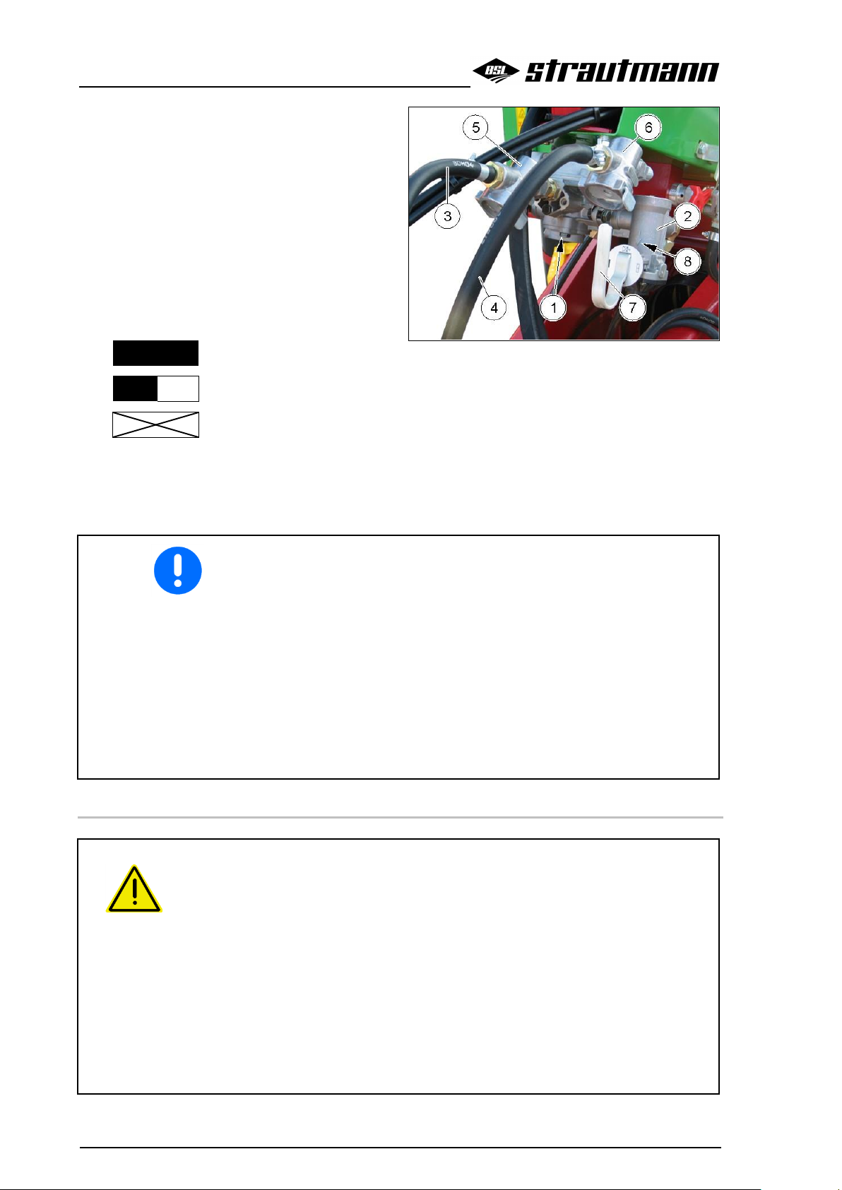
Commissioning
82
Verti-Mix 951-1651, Verti-Mix 951-L, 1251-L, Verti-Mix 1501 D-3101 D 05.16
(1) Trailer brake valve
(2) Brake pressure regulator
(3) Feed line with hose coupling (red)
(4) Brake line with hose coupling (yellow)
(5) In-line filter of feed line
(6) In-line filter of brake line
(7) Hand lever for adapting the braking effect
(8) Reading point of the set braking effect
"Full load"
Fig. 44
"Half load"
"Release"
Example:
Machine filled = Turn hand lever (7) such that the
"Full load" symbol is beneath the reading point
(8).
It is absolutely imperative to adapt the braking effect of the dual-line
service brake system via the brake pressure regulator to the current
loading condition of the machine before carrying out transport
journeys.
Only with the braking effect adapted:
will the pressure released by the trailer brake valve be limited,
will there be no run-on pushes,
will it be possible to sensitively and gradually slow down the
combination of tractor / machine,
will the tractor / machine combination remain in straight position
due to advanced braking.
WARNING
Risk of crushing, cuts, becoming entangled, being drawn in and risk of
impact to people due to improper functioning of the service brake system!
When connecting the brake and feed line, ensure that:
the sealing rings of the hose couplings are clean,
the sealing rings of the hose couplings seal tightly.
Immediately replace damaged sealing rings.
Drain the air reservoir every day before the first trip.
Only start the tractor with the hitched machine moving when the pressure
gauge of the compressed-air brake system on the tractor indicates 5.0 bar.
Check the course of the connected brake lines! The brake lines must not chafe
against external components.
5.9.3.1 Connect brake and feed line

Commissioning
Verti-Mix 951-1651, Verti-Mix 951-L, 1251-L, Verti-Mix 1501 D-3101 D 05.16
83
WARNING
Risk of crushing, cuts, becoming entangled, being drawn in and
risk of impact to people if the machine rolls due to the service
brake system being released!
Always connect the hose coupling of the brake line (yellow) first and
then the hose coupling of the feed line (red).
The machine's service brake system immediately comes off the brake
position if the red hose coupling is connected.
1. Open the caps of the hose couplings on the tractor.
2. Remove the hose coupling of the brake line (yellow) from the blank connection.
3. Clean soiled sealing rings or replace damaged sealing rings.
4. Properly fix the hose coupling of the brake line (yellow) to the yellow marked coupling device at
the tractor.
5. Remove the hose coupling of the feed line (red) from the blank connection.
6. Clean soiled sealing rings or replace damaged sealing rings.
7. Properly fix the hose coupling of the feed line (red) to the red marked coupling device at the
tractor.
8. Use the brake pressure regulator to adapt the braking effect of the service brake system to the
current loading condition of the machine.
9. Release the parking brake of the machine and / or remove the chocks.
WARNING
Risk of crushing, cuts, becoming entangled, being drawn in and
risk of impact to people if the machine rolls due to the service
brake system being released!
Always disconnect the hose coupling of the feed line (red) first and
then the hose coupling of the brake line (yellow).
The machine's service brake system only moves to brake position if
the red hose coupling is disconnected.
It is imperative to observe this order, as otherwise the service brake
system will be released and the non-braked machine may start to
move.
When the machine is unhitched or torn off, the feed line connected to
the trailer brake valve bleeds. The trailer brake valve automatically
switches over thus actuating the service brake according to the set
braking effect.
1. Secure the machine against rolling. Observe the information in the chapter "Secure tractor and
machine against accidental starting and rolling", page 62.
2. Release the hose coupling of the feed line (red).
3. Release the hose coupling of the brake line (yellow).
4. Fix the hose couplings to the blank connections.
5. Close the caps of the hose couplings at the tractor.
5.9.3.2 Disconnect brake and feed line

Commissioning
84
Verti-Mix 951-1651, Verti-Mix 951-L, 1251-L, Verti-Mix 1501 D-3101 D 05.16
WARNING
Risk of crushing, entanglement and impact for people if the
machine accidentally rolls during manoeuvring work with the
service brake released!
Tightly connect the machine with the braked manoeuvring vehicle
before releasing the service brake by means of the hand lever at the
brake pressure regulator. Now the machine must be exclusively
slowed down by the manoeuvring vehicle.
1. Hitch the machine to the braked manoeuvring vehicle.
2. Release the parking brake of the machine.
3. Swivel the hand lever at the brake pressure regulator to "Release" position.
The service brake is released and the machine can be manoeuvred.
4. Manoeuvre the machine by means of the manoeuvring vehicle.
5. Apply the parking brake of the manoeuvring vehicle after manoeuvring.
6. Swivel the hand lever at the brake pressure regulator back to its initial position after
manoeuvring.
The system pressure from the air reservoir slows the machine down.
7. Apply the parking brake of the machine.
8. Unhitch the machine from the manoeuvring vehicle.
(1) Hydraulic sleeve ISO 5676
Fig. 45
(2) Hydraulic cylinder of braking axle
Fig. 46
2
5.9.3.3 Manoeuvre unhitched machine by means of a manoeuvring vehicle
5.9.4 Hydraulic service brake system
The controlled hydraulic service brake system is connected to the special brake valve of the tractor.
When the brake pedal on the tractor is pressed down, the machine is slowed down.

Commissioning
Verti-Mix 951-1651, Verti-Mix 951-L, 1251-L, Verti-Mix 1501 D-3101 D 05.16
85
Only couple clean hydraulic clutches.
Clean hydraulic plug and hydraulic sleeve if necessary.
Slip the hydraulic plug into the hydraulic sleeve until the
hydraulic plug noticeably locks.
Check the coupling spot of the hydraulic brake line for correct
and tight seat.
The connected hydraulic brake line:
must easily give way to any movements during cornering
without any stress, buckling or chafing,
must not chafe against external components.
Check the hydraulic brake system for proper functioning before
carrying out transport journeys.
1. Remove the hydraulic sleeve (1) from the
machine's blanked-off connecting piece (2).
2. Couple the machine's hydraulic sleeve to
the tractor's hydraulic plug of the hydraulic
brake system.
3. Release the parking brake of the machine.
Fig. 47
(1) Crank handle; in adjusting position (2)
(2) Adjusting position
(3) Resting position, swivelled by 180°
compared to the adjusting position
(4) Spindle
(5) Cable
Fig. 48
5.9.4.1 Connect hydraulic brake system
5.9.4.2 Disconnect hydraulic brake system
1. Apply the parking brake of the machine.
2. Uncouple the hydraulic sleeve (Fig. 47/1).
3. Slip the hydraulic sleeve onto the machine's blanked-off connecting piece (Fig. 47/2).
5.9.5 Parking brake
The applied parking brake secures the unhitched machine against rolling. The parking brake is
actuated via spindle and cable when turning the crank handle.

Commissioning
86
Verti-Mix 951-1651, Verti-Mix 951-L, 1251-L, Verti-Mix 1501 D-3101 D 05.16
Ensure that the cable does not rest on or chafe against other vehicle
components.
With the parking brake released, the cable shall slightly sag.
Correct the setting of the parking brake if the tension path of the
spindle (4) is no longer sufficient.
Additionally observe the information in the chapter "Basic safety
instructions", page 35, when hitching and unhitching the
machine.
Check the machine for visible defects during each hitching and
unhitching procedure. Observe the information in the chapter
"Operator’s obligation", page 32.
WARNING
Risk to people of being crushed due to the tractor and the
machine accidentally starting or rolling when hitching or
unhitching the machine!
Only hitch or unhitch the machine after the tractor and the machine
have been secured against accidental starting and rolling.
Observe the information in the chapter "Secure tractor and machine
against accidental starting and rolling", page 62.
WARNING
Risk due to incorrect use of the tractor if the attached/ hitched
machine causes insufficient stability or insufficient steerability
and braking ability of the tractor!
Only attach/hitch the machine to appropriate tractors. Observe the
information in the chapter "Check tractor’s compatibility", page 58.
Release parking brake
1. Swivel the crank handle (1) from resting position (3) by 180° to adjusting position (2).
2. Turn the crank handle anticlockwise until the cable (5) is relieved.
The parking brake is released.
3. Swivel the crank handle to resting position.
Apply parking brake
1. Swivel the crank handle (1) from resting position (3) by 180° to adjusting position (2).
2. Turn the crank handle clockwise.
→ The parking brake is applied via the cable (2).
5.10 Hitch and unhitch machine
5.10.1 Hitch machine

Commissioning
Verti-Mix 951-1651, Verti-Mix 951-L, 1251-L, Verti-Mix 1501 D-3101 D 05.16
87
WARNING
Risk of being crushed and of impact to people standing between
tractor and machine while the machine is being hitched!
Make sure that people leave the hazardous area between tractor and
machine before approaching the machine.
Present helpers are only allowed to act as a guide next to the tractor
and the machine and to enter the space between the tractor and the
machine after the vehicles have completely stopped.
WARNING
Risk of crushing, cuts, being drawn in, becoming entangled and
risk of impact if the machine accidentally loosens from the
tractor!
Observe the maximum admissible tongue loads, towing
capacities and axle loads of the tractor.
Properly use and secure the provided coupling devices of the
tractor and the machine.
WARNING
Risk to people due to a failure of the power supply between
tractor and machine, caused by defective supply lines!
Observe the course of the supply lines during hitching. The supply
lines:
must easily give way to any movements during cornering without
any stress, buckling or chafing,
must not chafe against external components.
1. Secure the machine against rolling. Observe the information in the chapter "Secure tractor and
machine against accidental starting and rolling", page 62.
2. Always check the machine for visible defects during hitching. Observe the information in the
chapter "Operator’s obligation", page 32.
3. Couple the drawbar. Observe the information in the chapter "Couple drawbar", page 64.
4. Connect the hydraulic hose pipes. Observe the information in the chapter "Connect hydraulic
hose pipes", page 75.
5. Connect the brake system. Observe the information in chapters:
Hydraulic service brake, from page 77,
Automatic reverse overrun brake system, from page 79,
Dual-line compressed-air brake system, from page 81.
Hydraulic service brake system, from page 84,
6. Couple the propeller shaft. Observe the information in the chapter "Couple propeller shaft", from
page 70.
7. Insert the Bowden cable control set / the control unit into the holder of the tractor.
8. Connect the electrical supply lines / lighting system.
9. Lift the supporting leg to transport position. Observe the information in chapters:
"Lift mechanical supporting leg to transport position", page 72,
"Lift hydraulic supporting leg to transport position", page 73.
10. Release the parking brake of the machine. Observe the information in the chapter "Parking
brake", page 85.

Commissioning
88
Verti-Mix 951-1651, Verti-Mix 951-L, 1251-L, Verti-Mix 1501 D-3101 D 05.16
WARNING
Risk of being crushed, cut, drawn in, becoming entangled and
risk of impact to people due to insufficient stability of the
unhitched machine!
Park the empty machine on even, firm ground.
Secure the machine against rolling.
Ensure that there is always still enough free space in front of the
machine when unhitching the machine such that the tractor can
reapproach the machine in true alignment for hitching the machine
again.
1. Lower the supporting leg to support position. Observe the information in chapters:
"Lift mechanical supporting leg to transport position", page 72,
"Lift hydraulic supporting leg to transport position", page 73.
2. Secure the machine against rolling. Observe the information in the chapter "Secure tractor and
machine against accidental starting and rolling", page 62.
3. Always check the machine for visible defects during unhitching. Observe the information in the
chapter "Operator’s obligation", page 32.
4. Disconnect the electrical supply lines / lighting system.
5. Disconnect the hydraulic hose pipes. Observe the information in the chapter "Disconnect
hydraulic hose pipes", page 76.
6. Disconnect the brake system. Observe the information in chapters:
Hydraulic service brake, from page 77,
Automatic reverse overrun brake system, from page 79,
Dual-line compressed-air brake system, from page 81.
Hydraulic service brake system, from page 84,
7. Uncouple the propeller shaft. Observe the information in the chapter "Uncouple propeller shaft
from tractor", page 71.
8. Insert the Bowden cable control set / the control unit into the holder on the machine.
9. Uncouple the drawbar. Observe the information in the chapter "Uncouple drawbar", page 66.
The container attachment (1) increases the
mixing capacity and additionally prevents the
fodder from being thrown over the container
edge. For this purpose, the container attachment
is screwed on starting at the container edge (2).
The overflow ring (3) is mounted at the top edge
of the container attachment.
Fig. 49
5.10.2 Unhitch machine
5.11 Container attachment
Optional extra

Commissioning
Verti-Mix 951-1651, Verti-Mix 951-L, 1251-L, Verti-Mix 1501 D-3101 D 05.16
89
● Only authorised and qualified staff is allowed to mount the
container extension!
● The manufacturer will not assume any warranty and liability for
material damage and personal injuries if the work is carried out
by insufficiently qualified staff.
● Only use original Strautmann spare parts.
Risk of damage to the machine due to overload caused by filling too
much mass into the mixing container due to a non-approved
extension! Exclusively use approved extensions.
The maximum extension height is 360 mm, only 180 mm on
the Verti-Mix 1451!
Combining different extensions is not allowed!
Observe the fact that the container extension increases the
vehicle height. Observe the information in the chapter
"Technical data", page 18
The conveyor speed for the crossover conveyor / C-conveyor / discharge conveyor for side discharge
is infinitely adjustable.
The set conveyor speed determines the lateral delivery distance (throwing range) of the fodder next to
the machine. An increasing conveyor speed results in a larger lateral delivery distance of the fodder.
The conveyor speed is infinitely adjusted at the current regulation valve:
manually directly on the machine,
by remote control via the control set from the tractor.
The set scale value is not an absolute value for the conveyor speed, but only a reference
value. Depending on the tractor model, the set conveyor speed may differ even if the scale
value is identical.
Set the conveyor speed directly on the machine
via the rotary knob (1) at the current regulation
valve (2). Position (3) indicates the scale value
for the set conveyor speed.
Scale value 0 = lowest conveyor speed,
Scale value 10 = highest conveyor speed.
Fig. 50
5.12 Set conveyor speed
5.12.1 Manual setting of conveyor speed

Commissioning
90
Verti-Mix 951-1651, Verti-Mix 951-L, 1251-L, Verti-Mix 1501 D-3101 D 05.16
Set the conveyor speed via the control dial (1) on
the control set. Pointer (2) indicates the scale
value for the set conveyor speed:
Scale value 0 = lowest conveyor speed,
Scale value 10 = highest conveyor speed.
Fig. 51
The E-control set provides you with the option to adapt the control
range of the control dial and thus the drive speed of the conveyor
(crossover conveyor, side discharge conveyor, conveyor extension
or C-conveyor) to your needs.
The control dial is factory-set such that in normal operating mode
the conveyor slowly starts to run in position 2 and approximately
reaches its maximum drive speed in position 10.
WARNING
Risk of becoming entangled, being drawn in and wound up by
the running crossover conveyor, side discharge conveyor,
conveyor extension or C-conveyor!
Make sure that people or animals leave the hazardous area of the
conveyor before powering the conveyor.
Immediately switch the conveyor off if people or animals enter the
hazardous area of the conveyor.
1. Hitch the machine to the tractor:
1.1 Couple drawbar.
1.2 Connect hydraulic flow line and
return line.
1.3 Connect control set of the Econtrol.
2. Secure tractor and machine against
rolling.
3. Insert the blade of a screwdriver into the
slit (1) on the right-hand side of the
control set and force open the casing by
pressing the screwdriver handle
outwards.
The casing of the control set can
only be completely folded open on
the right-hand side.
Fig. 52
5.12.2 Set conveyor speed via control set
5.12.3 Set control dial range of E-control set

Commissioning
Verti-Mix 951-1651, Verti-Mix 951-L, 1251-L, Verti-Mix 1501 D-3101 D 05.16
91
4. Start the machine and switch the
conveyor on.
5. Set the control dial (2) to position 2
(minimum drive speed).
6. Turn the screw at the trimmer
potentiometer P2 to change the minimum
drive speed of the conveyor until it runs at
the desired speed (current approx.
0.6-1.9 A).
7. Set the control dial (2) to position 10
(maximum drive speed).
8. Turn the screw at the trimmer
potentiometer P3 to change the maximum
drive speed of the conveyor until it runs at
the desired speed (max. current 2.5 A).
9. Finally, turn the control dial and observe
the conveyor to check the entire control
range.
Adjust the control range as described in
steps 5-8 if necessary.
With the control dial range
being reduced, the other
hydraulic functions are
reduced as well as long as the
conveyor is running.
In case of a conveyor failure,
the other hydraulic functions
can still be operated.
10. Close the casing of the control set.
Fig. 53
1. Fix the holder (1) with the pocket (2) for the
Bowden cable control set within view and
easy reach at an appropriate spot in the
tractor’s cabin.
2. Insert the Bowden cable control set into the
pocket (2).
Fig. 54
5.13 Mount control set on the tractor
5.13.1 Mount holder with pocket for Bowden cable control set

Commissioning
92
Verti-Mix 951-1651, Verti-Mix 951-L, 1251-L, Verti-Mix 1501 D-3101 D 05.16
1. Mount the holder (1) with the mounting
element (2) for the control set on the tractor
within view and easy reach to the driver's
right.
2. Insert the mounting element for the control
set into the holder.
3. Plug the 3-pole plug (DIN 9680) of the
power cable into the 3-pole socket of the
tractor.
(Pole 15/30 = Plus; Pole 31 = Minus)
Fig. 55
Do not draw the current from the light socket.
Retrofit the 3-pole socket if your tractor is not equipped with a 3-
pole socket. An appropriate retrofit kit is available.
A constant power supply of 12 V is required. The 3-pole socket
must be protected by a fuse of at least 25 A.
The feed line of the 3-pole socket must have a minimum cable
cross section of 4 mm2.
The battery of the weighing device enables the
use of the weighing device when the machine is
not connected with the tractor.
The signal lamp (1) displays the status of the
system:
● flashes green: Battery is fully charged,
● flashes red/green: Battery is being
charged,
● flashes red: The weighing device is
supplied by the battery.
When the machine is not connected with the
tractor by means of the three-pole plug, press the
button (2) to activate the power supply via
battery. The signal lamp flashes red and the
weighing device is supplied with power for 45
minutes.
Fig. 56
5.13.2 Mount E-control set on the tractor
5.14 Battery for weighing device
Optional extra

Commissioning
Verti-Mix 951-1651, Verti-Mix 951-L, 1251-L, Verti-Mix 1501 D-3101 D 05.16
93
If the voltage of the additional battery falls below 10.5 V, charging
via the battery management is no longer possible!
In this case, a separate power supply unit with connecting cable is
required.
Operation of weighing device without connection to tractor
Minimum charging time of
battery
15 min
0.5 h
30 min
1.0 h
45 min
1.5 h
60 min
2.0 h
WARNING
Risk of injury due to movements of the machine or its working
tools!
Secure the machine against accidental starting, rolling and actuation!
1. Lower the dosage gate(s) completely.
2. Unscrew the nut (4).
3. Move the adjusting sheet (3)
● up (1): the deflector plate (5) swivels
out to its maximum extent when the
dosage gate is lifted.
● down (2): the deflector plate (5)
swivels out to its minimum extent
when the dosage gate is lifted.
4. Retighten the nut (4).
Fig. 57
Charge battery
The battery is charged if the three-pole plug of the E-control set is connected with the tractor.
Precondition for the charging procedure is a socket in the tractor which is not switched via the ignition
system. Otherwise, the battery is only charged with the ignition system switched on.
Approx. 11 hours are required to completely charge an empty battery. In order to ensure trouble-free
operation, provide for a sufficient minimum charging time.
If the required minimum charging time cannot be reached, an additional power supply unit will be
required which enables charging of the battery independently of the tractor. The electronic system of
the charging equipment prevents overloading. The power supply unit is connected with the three-pole
plug of the E-control set by means of a charging cable.
5.15 Set deflector plate
Mechanical deflector plate

Commissioning
94
Verti-Mix 951-1651, Verti-Mix 951-L, 1251-L, Verti-Mix 1501 D-3101 D 05.16
Fig. 58
Use the locking bolt (2) to set the throwing range
of the deflector plate (1):
● Locking bolt (2) in drilled hole (3) =
Maximum swivelling-out of deflector plate
(1).
● Locking bolt (2) in drilled hole (4) =
Minimum swivelling-out of deflector plate
(1).
1. Remove the split-pin (6) and the washer
(5).
2. Remove the locking bolt (2) from the
respective drilled hole.
3. Position the hydraulic cylinder above the
desired drilled hole and insert the locking
bolt (2).
4. Mount the washer (5).
5. Use a new split-pin to secure the washer.
Fig. 59
Hydraulic deflector plate
Optional extra

Operation
Verti-Mix 951-1651, Verti-Mix 951-L, 1251-L, Verti-Mix 1501 D-3101 D 05.16
95
Depending on the machine’s equipment, actuation of the machine’s hydraulic and electrical function(s)
is effected via remote control from the tractor:
● via direct tractor connection (standard equipment)
● via Bowden cable operation (optional extra)
● via electro-hydraulic operation (E-control) (optional extra)
● via the weighing and control set (Multiscale) (optional extra)
The actuating speed of the hydraulic functions (hydraulic
components) depends on the tractor's hydraulic system.
Depending on the tractor model, a correction of the set actuating
speeds at the tractor's control device / the machine's control
block may be necessary.
For information about the required control devices, please refer
to the chapter "Required tractor equipment“ on page 29.
The individual hydraulic components of the
machine are connected to a control block. To
ensure the oil supply, the control block is
connected to the hydraulic system of the tractor
via a double-acting control device or a singleacting control device and a free return line.
If the machine is equipped with an on-board
hydraulic system, it is not necessary to connect
the machine to the hydraulic system of the
tractor.
The Bowden cable control set serves to actuate
the hydraulic functions of the machine from the
tractor if the oil circulation between tractor and
machine has been switched on via the control
device on the tractor.
One operating element is required for each
function of the machine.
The Bowden cable control set
is mounted on the tractor within view and
easy reach of the operator,
is equipped with one or several operating
element(s).
The operating elements are in touch-control or in
Fig. 60
6 Operation
6.1 Direct tractor connection
The individual hydraulic components of the machine are directly connected to the hydraulic system of
the tractor via appropriate hydraulic hose pipes for oil supply.
A double-acting control device is required on the tractor for each function (hydraulic component) of the
machine.
Each individual function of the machine is then actuated from the tractor via the operating element on
the appropriate control device.
6.2 Bowden cable control set

Operation
96
Verti-Mix 951-1651, Verti-Mix 951-L, 1251-L, Verti-Mix 1501 D-3101 D 05.16
latch-in design:
In touch-control design for folding,
swivelling or sliding movable machine parts,
e. g. discharge door, hydraulic countercutters, supporting leg etc. The function is
only carried out when the operating element
is activated and kept hold of. As soon as
the operating element is released, it returns
to its neutral position and the action is
stopped.
In latch-in design for movements requiring
continuous action for constant loads, e. g.
hydraulic motor of discharge conveyor.
The operating elements can be set to a
maximum of 3 positions:
Function I,
Neutral position,
Function II.
The following paragraphs show the possible symbols on the control set and their meaning.
Symbol
Position of hand lever
Discharge door
front
(touch-control)
right
open
neutral position
no action
rear
(touch-control)
right
close
front
(touch-control)
left
open
neutral position
no action
rear
(touch-control)
left
close
front
(touch-control)
front / rear
open
neutral position
no action
rear
(touch-control)
front / rear
close
6.2.1 Possible symbols and their meaning
Open / Close discharge door
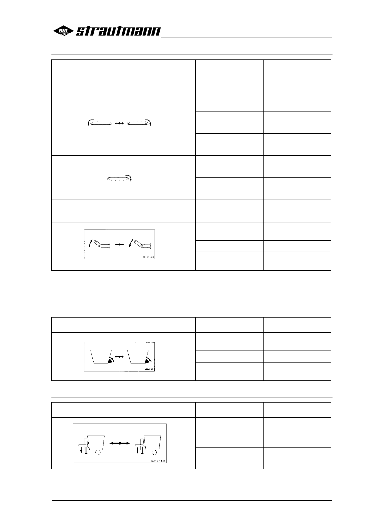
Operation
Verti-Mix 951-1651, Verti-Mix 951-L, 1251-L, Verti-Mix 1501 D-3101 D 05.16
97
Symbol
Position of hand lever
Crossover conveyor /
Conveyor extension /
Discharge conveyor
front
(latch-in design)
crossover conveyor *
ON to the left
neutral position
crossover conveyor
OFF
rear
(latch-in design)
crossover conveyor *
ON to the right
front
(latch-in design)
discharge conveyor
ON
neutral position
discharge conveyor
OFF
Position of hand lever
Conveyor extension /
Discharge conveyor
front
(touch-control)
swivel up to transport
position
neutral position
action stops
rear
(touch-control)
swivel down to working
position
* At the same time, the conveyor extension is powered if a conveyor extension is mounted in the
conveying direction of the crossover conveyor. If the material is conveyed away from the
conveyor extension, the conveyor extension will stop.
Symbol
Position of hand lever
Counter-cutters
front
(touch-control)
extend (in)
neutral position
no action
rear
(touch-control)
retract (out)
Symbol
Position of hand lever
Supporting leg
front
(touch-control)
lift to transport position
neutral position
no action
rear
(touch-control)
lower to support position
Switch crossover conveyor / conveyor extension / discharge conveyor
Extend and retract counter-cutters
Lift / Lower supporting leg

Operation
98
Verti-Mix 951-1651, Verti-Mix 951-L, 1251-L, Verti-Mix 1501 D-3101 D 05.16
Symbol
Position of hand lever
Speed
front
(latch-in design)
fast
gear level I
rear
(latch-in design)
slow
gear level II
For changing the gear level, swivel
the Bowden cable lever (1) into the
required position. Beware of the
fact that the Bowden cable lever
(1) engages in the selected
position at the notch after changing
gear.
Fig. 61
Symbol
Position of hand lever
Deflector plate
front
(touch-control)
extend (in)
neutral position
action stops
rear
(touch-control)
retract (out)
Symbol
Position of hand lever
C-conveyor
front
(touch-control)
retract
neutral position
action stops
rear
(touch-control)
extend
Change mixing auger speed
Extend and retract deflector plate
Displace C-conveyor

Operation
Verti-Mix 951-1651, Verti-Mix 951-L, 1251-L, Verti-Mix 1501 D-3101 D 05.16
99
The individual hydraulic components of the
machine are connected to a control block. To
ensure the oil supply, the control block is
connected to the hydraulic system of the tractor
via a double-acting control device or a singleacting control device and a free return line.
If the machine is equipped with an on-board
hydraulic system, it is not necessary to connect
the machine to the hydraulic system of the
tractor.
The E-control set serves to actuate the hydraulic
functions of the machine from the tractor if the oil
circulation between tractor and machine has
been switched on via the control device on the
tractor.
Fig. 62
In case of longer downtimes of the machine, switch the control set off,
in order to avoid a discharging of the tractor’s battery due to switchedon loads!
6.3 E-control set
One operating element is required for each function of the machine.
The control set:
● is differently designed depending on the machine's equipment,
● is mounted on the tractor within view and easy reach such that the operating elements are
easily accessible,
● must be connected to the tractor's power supply (12 V) via the 3-pole plug (DIN 9680),
● is equipped with several operating elements such as key buttons, toggle switches and, where
applicable, a control dial.
The operating elements are in touch-control design (key buttons), in latch-in design (toggle switches)
or in control-dial design:
● In touch-control design for folding, swivelling or sliding movable machine parts, e. g. dosage
gate, hydraulic counter-cutters, supporting leg, etc. The function is only carried out if the
operating element is kept hold of. As soon as the operating element is released, it returns to its
neutral position and the action is stopped.
● In latch-in design for movements requiring continuous action for constant loads e. g. hydraulic
motors.
● Control dials for setting the actuating speed of the hydraulic functions in 10 steps (e.g. conveyor
speed for crossover conveyor / discharge conveyor).
The operating elements in touch-control or in latch-in design can be set to a maximum of 3 positions:
● Function I
● Neutral position
● Function II
6.3.1 Functions and their symbols
The following paragraphs show the symbols of the operating elements of the control set and their
functions.

Operation
100
Verti-Mix 951-1651, Verti-Mix 951-L, 1251-L, Verti-Mix 1501 D-3101 D 05.16
Symbol
Position of toggle
switch
Control set
top
(latch-in design)
Work lights
ON
I (On)
Middle
ON
(red control lamp lights
up)
0 (Off)
(latch-in)
OFF
(red control lamp does
not light up)
Symbol
Position of key button
Discharge door
top
(touch-control)
open
neutral position
action stops
bottom
(touch-control)
close
Symbol
Position of key button
C-conveyor
top
(touch-control)
retract
neutral position
action stops
bottom
(touch-control)
extend
Switch control set on / off
Open / Close discharge door
Displace C-conveyor
 Loading...