

STRATO BACwALL 324 Specification & Installation Instructions
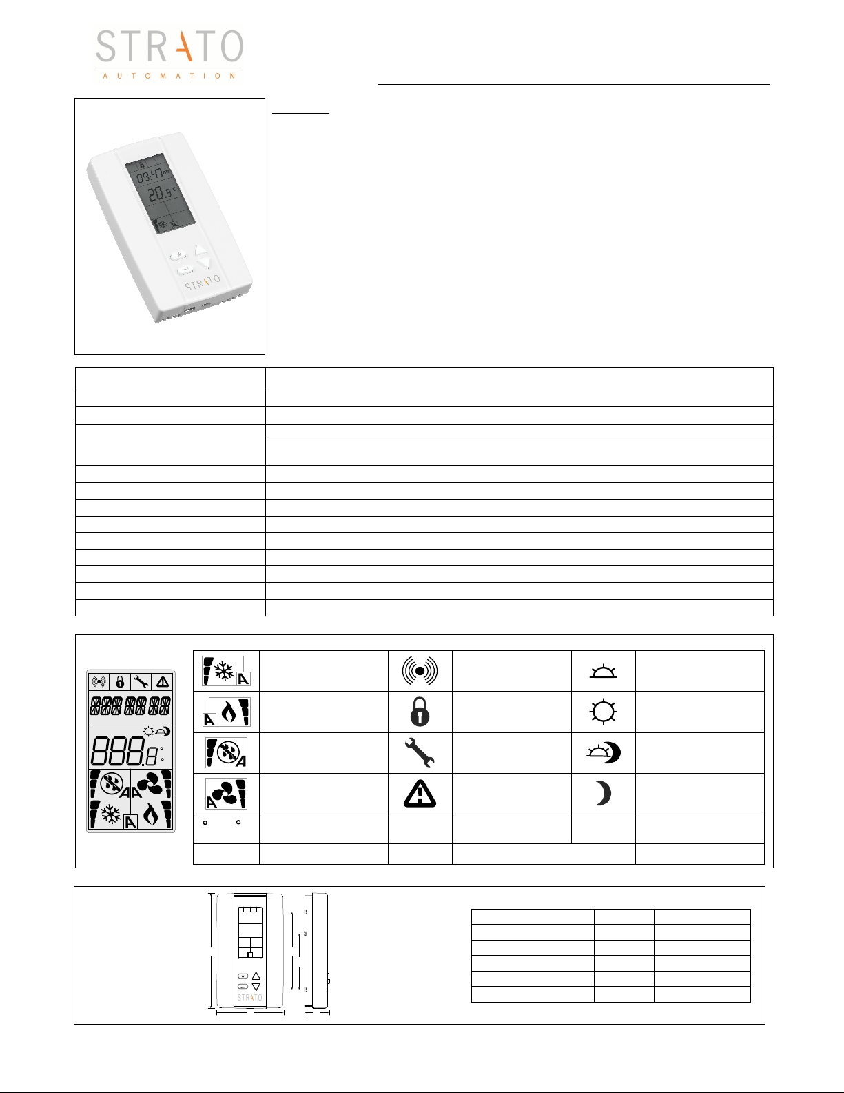
High performance wall controll
er
C
Dimension
Inches
Metric (mm)
A
B
C
D
E
Feature
s:
BACwALL 324
Specification & Installation instructions
Technical Data
Power supply
Output
Power consumption
Set point range
Control accuracy
Electrical connection
Operating temperature
Storage temperature
Relative Humidity
Degree of protection of housing
Weight
Presentation
Symbols on display
PM
AM
.
.
.
.
MO TU WE TH FR S A SU
%RH
C
F
or F
• Attractive modern look with large LCD and backlight
• Icons driven information and 1 line of text information
• Selectable analog and digital input/output
• Selectable Fahrenheit or Celsius scale
• Manual Night Set Back override
• Totally programmable
• Fully versatile
• Real time clock
• Powerful application flexibility
• Operates stand alone
• USB plug for portable device convenience
• BACnet® MS/TP @ 9600, 19200, 38400, 76800, 115200bps
• Selectable device Instance and MAC Address
Input
3 Analog universal (0..3.3VDC or 0..10VDC or thermistor or digital input dry contact)
Cooling ON
33, 66, 100% output
A: Automatic
Heating ON
33, 66, 100% output
A: Automatic
Humidify/Dehumidify
33, 66, 100% output
A: Automatic
Fan ON
3rd speed activated
A: Automatic
ºC: Celsius scale
ºF: Fahrenheit scale
BACwALL 324
22..26 VAC 50/60Hz
2 Analog outputs 0..10VDC (2500Ω impedance min.)
4 binary triac (on/off, pulse 0 or 24 VAC, 0.350 A max.),
%RH
Sink or source with protection
1.2 VA without output loading or 35 VA max.
10ºC..35ºC [50ºF..95ºF]
Temperature: +/-0.2ºC [0.4ºF]
0.8 mm2 [16 AWG] maximum
0ºC..50ºC [32ºF..122ºF]
-30ºC..+50ºC [-22ºF..+122ºF]
10..90 % non condensing
IP 30 to (EN 60529)
150.5 g. [0.33 lb]
Communication
Status
Menu set-up Lock
Programming mode
(Technician setting)
Alarm Status
Percentage of
humidity
MO TU WE TH FR SA SU
AM
PM
Morning
Day
Evening
Night
Morning
Afternoon
Day of the week
Dimensions
BACwALL specification & installation sheet // 120412
2.85 73
B
E
D
4.85 123
1.00 24
2.36 60
3.27 83
A
1
C
BACwALL 324
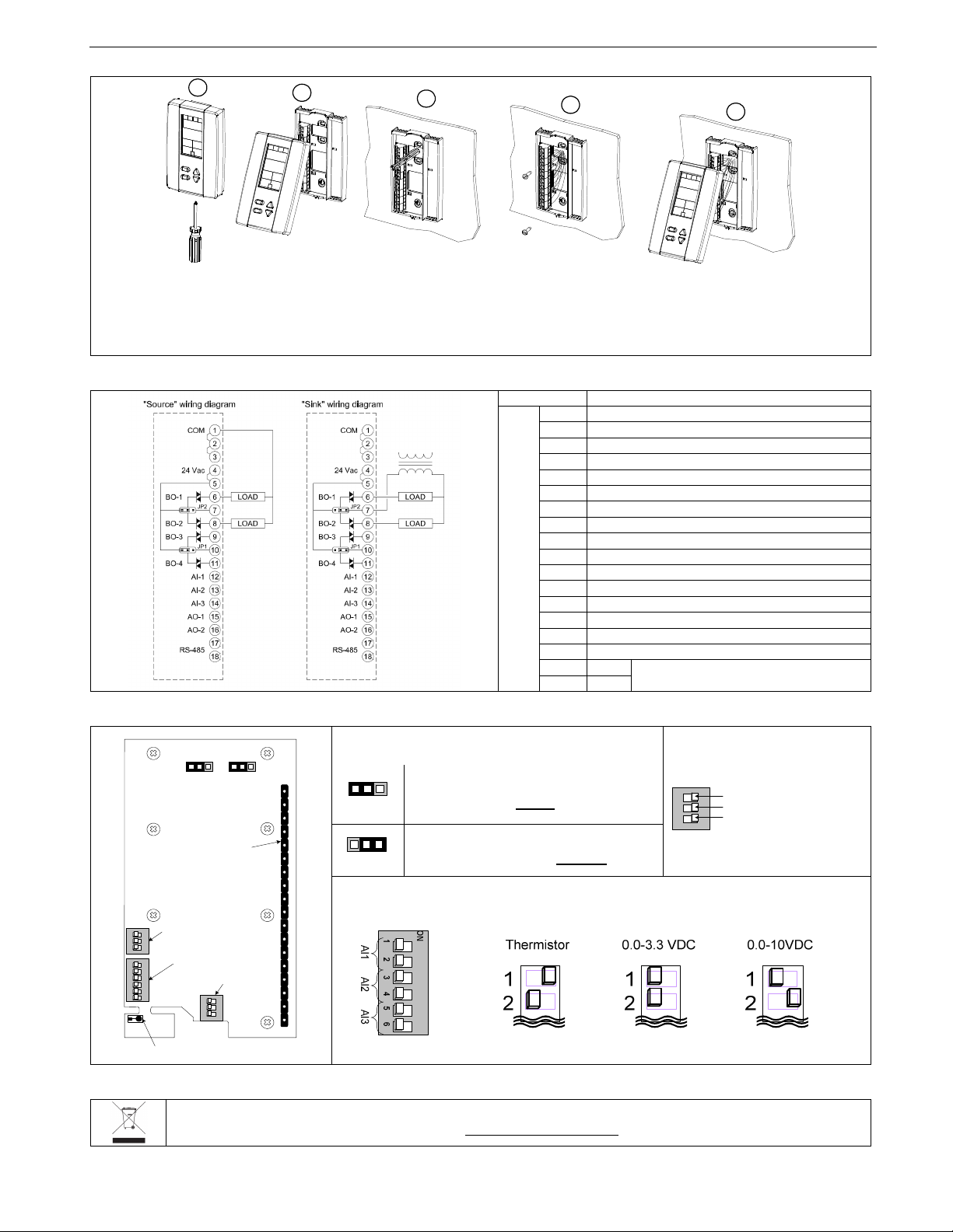
E. Mount the control module on the base and secure using the screw.
2
9
16
Digital output signal selection
RS-485 dip switch (DS
3)
n (Last node)
O
Specification & Installation instructions
Mounting Instructions
A
CAUTION: Risk of malfunction. Remove power prior to separate thermostat cover from its base.
A. Remove the screw (captive) holding the base and the front cover of the thermostat.
B. Lift the front cover of the thermostat to separate it from the base.
C. Pull wire through the base hole.
D. Secure the base to the wall using wall anchors and screws (supplied). Make the appropriate connections.
B
C
D
Terminal description
Terminals BACwALL 324
1 Common
Common
3 Common
4 24 VAC
5 24 VAC
6 Binary output 1 (BO1)
7 Common (BO1 & BO2)
8 Binary output 2 (BO2)
TB1
Binary output 3 (BO3)
10 Common (BO3 & BO4)
11 Binary output 4 (BO4)
12 Analog input 1 (AI1)
13 Analog input 2 (AI2)
14 Analog input 3 (AI3)
15 Analog output 1 (AO1)
Analog output 2 (AO2)
17 A+
18 B-
Communication port RS 485
Settings on PC Board
E
JP1
JP2
24VAC
24VAC
TB1
Connecting
strip TB1
DS1
ON
1 2 3
Reserved
ON
Analog input
DS2
1 2 3 4 5 6
Dip switch
Temperature sensor
RS-485
Dip switch
ON
1 2 3
DS3
Recycling at end of life
At end of life, please return the thermostat to your Strato Automation local distributor for recycling. If you need to find the nearest
Strato Automation authorized distributor, please consult www.stratoautomation.com.
BACwALL specification & installation sheet // 120412
2
(JP1 for BO3 & BO4 - JP2 for BO1 & BO2)
1 2 3 4 5 6 7 8 9 10 11 12 13 14 15 16 17 18
24VAC
Jumper on 24VAC: All digital output
signal is linked to 24 vac. (source)
Jumper on TRIAC COM: All digital
BO COM
output signal is linked to BO com. (sink)
N
1
2
3
Reserved
120 ohm terminatio
Reserved
Analog input dip switch (DS2)
 Loading...