

Page 1

User Manual
Page 2

Page 3

Eclipse
Microwave Radio System
User Manual
Page 4

Page 5

Eclipse User Manual
260-668045-001 Rev 005 March 2004
Copyright © 2003 - 2004 by Stratex Networks
All rights reserved. No part of this publication may be reproduced, transmitted, transcribed, stored in a retrieval
system, or translated into any language or computer language, in any form or by any means, electronic, magnetic,
optical, chemical, manual or otherwise, without the prior written permission of Stratex Networks.
Printed in New Zealand
Disclaimer
Stratex Networks makes no representation or warranties with respect to the contents hereof and specifically disclaims
any implied warranties or merchantability or fitness for any particular purpose. Further, Stratex Networks reserves the
right to revise this publication and to make changes from time to time in the content hereof without obligation of
Stratex Networks to notify any person of such revision or changes.
This equipment has been tested for and meets EMC Directive 89/336/EEC. The equipment was tested using screened
cabling. If any other type of cable is used, it may violate compliance.
Trademark
Windows is a registered trademark of Microsoft Corporation in the United States and other countries.
Andrew name and logo is a registered trademark of Andrew Corporation.
The HUBER+SUHNER word as well as the H+S word and the HUBER+SUHNER logo are registered trademarks
and/or service marks of HUBER+SUHNER AG.
Page 6

For sales information, contact one of the following regional Stratex Networks offices, during normal business hours.
For Customer Service, contact one of the regional Technical Helpdesks listed below.
You can also call your local Stratex Networks office. Contact information is available on our website:
www.stratexnet.com
Corporate Headquarters
Americas Headquarters
Europe Headquarters
Stratex Networks
120 Rose Orchard Way
San Jose, CA 95134-1358
U.S.A.
Stratex Networks
Regus, Central Boulevard
Blythe Valley Business Park
Solihull, Westmidland
B90 8AG
United Kingdom
Phone: +1-408-943-0777
Facsimile: +1-408-944-1801
Phone: +44-1564-711084
Facsimile: +44-1564-711335
Asia Pacific Headquarters Middle East, Africa and CIS
Headquarters
Stratex Networks
10 Ang Mo Kio Street 65
#03-13 Techpoint
Singapore 569059
Stratex Networks
API World Tower
Suite 302 A
Sheikh Zayed Road
Dubai, P.O. Box 32423
United Arab Emirates
Phone: +65-6484-7780
Facsimile: +65-6484-7768
Phone: +97-1433-25600
Facsimile: ++97-1433-25700
Americas Technical Helpdesk EMEA Technical Helpdesk Asia Pacific Technical Helpdesk
Stratex Networks
120 Rose Orchard Way
San Jose, CA 95134-1358
U.S.A.
Stratex Networks
4 Bell Drive
Hamilton International Technology Park
Blantyre, Scotland
G72 0FB
United Kingdom
Stratex Networks
Bldg 10, Unit B
Philexcel Industrial Park
Clark Special Economic Zone
Clark Field
Pampanga, Philippines
Phone:
+1 800 362 9283 (from within the US)
+1 408 944 3602 (English)
+1 408 944 3664 (Spanish)
Phone: +44 1698 717 230 Phone: +63 45 599 5192
Page 7
Declaration of Conformity
I hereby declare that the product Eclipse satisfies all the technical regulations applicable to the product within the
scope of Council Directives 73/23/EEC, 89/336/EEC and 99/5/EC:
All essential radio test suites have been carried out.
This declaration is issued under the sole responsibility of the manufacturer and, if applicable, his
authorized representative.
Point of Contact:
Callum Noon, +64 4 577 8800 (Tel), +64 4 577 8822 (Fax)
Eclipse L6GHz - EN 302 217, EN 301 489, EN 60950, IEC 529
Eclipse U6GHz - EN 302 217, EN 301 489, EN 60950, IEC 529
Eclipse 7/8GHz - EN 302 217, EN 301 489, EN 60950, IEC 529
Eclipse 11GHz - EN 302 217, EN 301 489, EN 60950, IEC 529
Eclipse 13GHz - EN 302 217, EN 301 489, EN 60950, IEC 529
Eclipse 15GHz - EN 302 217, EN 301 489, EN 60950, IEC 529
Eclipse 18GHz - EN 302 217, EN 301 489, EN 60950, IEC 529
Eclipse 23GHz - EN 302 217, EN 301 489, EN 60950, IEC 529
Eclipse 26GHz - EN 302 217, EN 301 489, EN 60950, IEC 529
Eclipse 28GHz - EN 302 217, EN 301 489, EN 60950, IEC 529
Eclipse 32GHz - EN 302 217, EN 301 489, EN 60950, IEC 529
Eclipse 38GHz - EN 302 217, EN 301 489, EN 60950, IEC 529
(Title(s) of regulations, standards, etc.)
NOTIFIED BODY: EMCC Dr. Rasek
MANUFACTURER or AUTHORISED REPRESENTATIVE:
Address: Address:
Boelwiese 5
91320 Ebermannstadt
Germany
(Notified body: 0678)
Stratex Networks
120 Rose Orchard Way
San Jose
CA 95134
USA
San Jose, 28 August, 2003
(Place, date of issue) (Signature)
CALLUM NOON, PRODUCT MANAGER
(Name and title in block letters)
Page 8

The Eclipse radio is classified under the R&TTE Directive 99/5/EC as a class 2.8 radio (microwave fixed link)
product. Point-to-point radio relay equipment is intended to be used for interconnecting typically private and public
networks and for interconnecting mobile base stations back to the PSTN point of presence (POP).
For details of where the equipment is intended to be used please refer to the Country matrix below. It should also be
noted that a licence to operate this apparatus is likely to be necessary and the appropriate regulatory administration
should be contacted.”
Stratex Networks intends to market this equipment where a cross (X) is shown.
Note: The information contained in this document has been gathered from the relevant government authorities.
Austria
Belgium
Denmark
Finland
France
Germany
Greece
Ireland
Italy
Netherlands
Luxembourg
Norway
Portugal
Spain
Sweden
Switzerland
UK
Eclipse L6GHz XXXXXXXXXXXXX XXX
Eclipse U6GHz XXXXXX XX X X X
Eclipse 7/8GHz XXXXXXXXXXXX XXXX
Eclipse 11GHz XXXX XX
Eclipse 13GHz XXXXXXXXXXXXXXXXX
Eclipse 15GHz XXXXXXXXXXXXXXXXX
Eclipse 18GHz XXXXXXXXXXXXX XXX
Eclipse 23GHz XXXXXXXXXXXXXXXXX
Eclipse 26GHz XXXXXXXXXXXXXXXXX
Eclipse 28GHz XXXX XX
Eclipse 32GHz XX X
Eclipse 38GHz XXXXXXXXXXXXXXXXX
0678
Page 9

260-668045-001 Rev 005 March 2004 vii
About this Manual
Welcome to Eclipse...................................................................................... xv
Purpose......................................................................................................... xv
Intended Audience ....................................................................................... xv
What You Need To Know ........................................................................... xvi
Organization................................................................................................ xvi
Additional Resources.................................................................................. xvi
Conventions and Terminology................................................................... xvii
Eclipse Health and Safety Requirements
Chapter 1. Introduction
Chapter 2. General Health and Safety
Flammability............................................................................................... 2-1
Hazardous Materials ...................................................................................2-1
Hazardous Voltage ...................................................................................... 2-1
Safety Signs ................................................................................................ 2-2
Surface Temperatures.................................................................................. 2-2
Chapter 3. Operator Health and Safety
Equipment Protrusions................................................................................3-1
Laser and Fiber Optic Cable Hazards ......................................................... 3-1
Lifting Equipment.......................................................................................3-2
Protection from RF Burns: Eclipse Radio .................................................. 3-2
Protection from RF Burns: General ............................................................3-2
Safety Warnings .......................................................................................... 3-2
Contents
Page 10

viii Stratex Networks
Chapter 4. General Hazards
Airflow Requirements.................................................................................4-1
Circuit Overloading .................................................................................... 4-1
Connections.................................................................................................4-2
Ground Connections ............................................................................4-2
Power Supply Connection ................................................................... 4-2
Power Supply Disconnect.................................................................... 4-2
Eclipse Indoor Unit Earthing ...................................................................... 4-2
ESD .............................................................................................................4-3
Fiber Optic Cables ......................................................................................4-3
Lightning Surge Suppressor........................................................................4-3
Mechanical Loading.................................................................................... 4-3
Restricted Access ........................................................................................ 4-4
Temperature ................................................................................................4-4
Maximum Ambient Temperature ........................................................4-4
Rack Mount Temperature Considerations ........................................... 4-4
Eclipse System Description
Not included in this version.
Eclipse Installation
Chapter 1. Introduction
Chapter 2. Eclipse Health and Safety Requirements
Chapter 3. Hardware Installation Overview
Page 11

Eclipse User Manual
260-668045-001 Rev 005 March 2004 ix
Chapter 4. Pre-Installation
Installation Tools and Equipment ............................................................... 4-2
Unpacking the Equipment .......................................................................... 4-3
Part Number and Serial Number Identification................................... 4-5
Verifying the System Configuration....................................................4-5
Installation Kits and Accessories................................................. 4-7
Chapter 5. Installation Overview
Chapter 6. Installing the Antenna and ODU
Installing the Antenna................................................................................. 6-1
Installing a Direct-Mount ODU..................................................................6-2
ODU Polarization ................................................................................6-3
Procedure ............................................................................................. 6-5
Grounding the ODU.................................................................................... 6-6
Installing the ODU Cable ........................................................................... 6-8
General Coaxial Cable Installation Guidelines.................................... 6-8
ODU Cable Options.............................................................................6-9
Belden 9913F7............................................................................. 6-9
Andrew BR-400C...................................................................... 6-10
ODU Cable Installation ..................................................................... 6-10
Jumper Cables.................................................................................... 6-11
Fitting Type N Cable Connectors...................................................... 6-11
Weatherproofing the ODU Type N Connector.................................. 6-12
Installing ODU Cable Grounding Kits .............................................. 6-13
Fitting the Lightning Surge Suppressor ............................................. 6-14
Non-Lightning Prone Sites........................................................ 6-14
Lightning Prone Sites ................................................................ 6-14
Suppressor Installation Procedure ............................................. 6-16
Page 12

x Stratex Networks
Chapter 7. Installing the INU and INUe
INU Installation Requirements ................................................................... 7-3
Installing an INU......................................................................................... 7-4
Installing Plug-in Cards ..............................................................................7-7
Basic Rules for Installing Plug-in Cards .............................................7-8
Plug-in Cards and Interfaces.............................................................. 7-10
NCC........................................................................................... 7-10
FAN ........................................................................................... 7-14
RAC........................................................................................... 7-14
DAC........................................................................................... 7-17
AUX........................................................................................... 7-23
NPC ........................................................................................... 7-24
Chapter 8. Installing the IDU
IDU Installation Requirements ................................................................... 8-3
Installing an IDU......................................................................................... 8-4
IDU Connector Data ...................................................................................8-6
NMS 10/100Base-T Connector ........................................................... 8-6
Maintenance V.24 Connector .............................................................. 8-7
Auxiliary Data Connector.................................................................... 8-8
Alarm I/O Connector ...........................................................................8-9
Tributary Connector Assemblies ....................................................... 8-10
Chapter 9. Antenna Alignment
Alignment via the RSL Graph on Portal..................................................... 9-2
Alignment using the RSSI Voltage at the ODU.......................................... 9-3
Antenna Alignment Process........................................................................9-4
Locating the Main Beam ..................................................................... 9-5
Tracking Path Error .............................................................................9-6
Page 13

Eclipse User Manual
260-668045-001 Rev 005 March 2004 xi
Portal Installation and Configuration
Chapter 1. PC Requirements
Hardware Requirements ............................................................................. 1-1
Software Requirements............................................................................... 1-2
Chapter 2. Getting Started
Installing Portal...........................................................................................2-1
Portal Connection Options...................................................................2-2
Configuring V.24 Connection...................................................... 2-2
Installing Ethernet Access ........................................................... 2-4
Portal Hardware Connection................................................................2-6
Connect Your PC to Eclipse Using a V.24 Connection............... 2-6
Connect Your PC to Eclipse Via Ethernet ................................... 2-6
Starting Portal ......................................................................................2-6
V.24 Dial Up ................................................................................ 2-6
Portal Start Up ............................................................................. 2-7
V.24 Access Check ...................................................................... 2-9
Portal Screens ........................................................................................... 2-10
Portal Logos.......................................................................................2-12
Portal Icons ........................................................................................ 2-12
Chapter 3. Eclipse Configuration
Installing an Eclipse Link ........................................................................... 3-2
Installation Menu................................................................................. 3-2
Licensing.............................................................................................. 3-5
Navigating the Licensing Screen................................................. 3-6
Upgrading a License.................................................................... 3-7
Configuration Menu....................................................................................3-8
Eclipse Node Slot Numbering and Conventions ............................... 3-11
Slot Loading Rules .................................................................... 3-11
New Installation................................................................................. 3-12
Information Configuration........................................................................ 3-13
Page 14

xii Stratex Networks
Layout Configuration................................................................................3-14
Navigating Layout Configuration......................................................3-15
Plug-Ins Configuration..............................................................................3-16
RAC and Radio Configuration ..........................................................3-18
Configuring the RAC or Radio.................................................. 3-20
DAC / Tributary Configuration .........................................................3-25
DAC 16x, DAC 4x, and Tributary............................................. 3-25
DAC 1x155o.............................................................................. 3-28
DAC ES ..................................................................................... 3-30
Protection Configuration...........................................................................3-36
Configuring Protection ......................................................................3-37
Circuits Configuration .............................................................................. 3-40
View and Configure Circuits .............................................................3-47
Networking Configuration ........................................................................3-51
Static or Dynamic Routing ................................................................3-51
Networking Screens...........................................................................3-52
Configuring Single IP Addressing and Dynamic Routing ........ 3-53
Configuring Single IP Addressing and Static Routing .............. 3-54
Configuring Interface IP Addressing and Routing .................... 3-55
Date and Time Configuration ................................................................... 3-57
Software Management ..............................................................................3-59
Diagnostics
Chapter 1. Diagnostics
System Summary ........................................................................................1-2
System Summary Navigation ..............................................................1-3
Event Browser............................................................................................. 1-4
Event Browser Navigation................................................................... 1-5
Event Box .................................................................................... 1-6
All Occurrences Box ................................................................... 1-6
Help Box...................................................................................... 1-6
Page 15

Eclipse User Manual
260-668045-001 Rev 005 March 2004 xiii
Alarms......................................................................................................... 1-7
Alarms Screen Navigation................................................................... 1-8
History ........................................................................................................1-9
History / Graph Screen Navigation.................................................... 1-10
History / Report Screen Navigation...................................................1-12
Performance .............................................................................................. 1-12
Performance Screen Navigation ........................................................1-13
System Controls........................................................................................ 1-14
LNK Menu.........................................................................................1-14
DAC or Tributary Menu ....................................................................1-15
Appendices
Appendix A. Declaration of Conformity Translation
Danish Declaration of Conformity ............................................................ A-2
Dutch Declaration of Conformity .............................................................. A-3
Finnish Declaration of Conformity............................................................ A-4
French Declaration of Conformity............................................................. A-5
German Declaration of Conformity........................................................... A-6
Greek Declaration of Conformity .............................................................. A-7
Italian Declaration of Conformity.............................................................. A-8
Norwegian Declaration of Conformity ...................................................... A-9
Portuguese Declaration of Conformity .................................................... A-10
Spanish Declaration of Conformity ......................................................... A-11
Swedish Declaration of Conformity ........................................................ A-12
Appendix B. Eclipse Radio Alarms
DAC Alarms .............................................................................................. B-1
NCC Alarms .............................................................................................. B-8
RAC Alarms ............................................................................................ B-23
Page 16

Appendix C. Installation Kits and Accessories
Standard Accessories ................................................................................. C-2
IDC ..................................................................................................... C-2
IDC V2 and IDCe ............................................................................... C-3
IDU ..................................................................................................... C-3
NCC .................................................................................................... C-3
RAC .................................................................................................... C-4
ODU.................................................................................................... C-4
Required Accessories................................................................................. C-5
RAC/IDU to ODU Cable Kits ............................................................ C-5
RAC/IDU Surge Protection Accessories ............................................ C-5
Optional Accessories ................................................................................. C-6
Non-spare DAC 4x, IDU 8x, or IDU 16x Accessories....................... C-6
Non-spare DAC 16x Accessories ....................................................... C-8
Non-spare DAC 155o Accessories ................................................... C-10
Non-spare DAC 2x155o ................................................................... C-11
Non-spare DAC 155e Accessories ................................................... C-12
Non-spare DAC 1xE3/DS3 Accessories .......................................... C-12
Non-spare DAC ES Accessories ...................................................... C-12
Optional ODU Accessories............................................................... C-13
Spare Accessories .................................................................................... C-13
INU or IDU Spare Accessories......................................................... C-13
RAC Spare Accessories.................................................................... C-14
Appendix D. ODU Cable Connector and Ground Kit Installation Instructions
BR-400 Connector Installation .................................................................. D-2
GK-400 Cable Ground Kit Installation...................................................... D-4
Page 17

Eclipse User Manual
260-668045-001 Rev 005 March 2004 xv
Appendix E. DAC Trib Connector and Cable Assembly Data
DAC 16x Mini RJ-21 to BNC Cable Assembly.........................................E-2
DAC 16x Mini RJ-21 to RJ-45 Straight and Crossover Cable AssembliesE-4
DAC 16x Mini RJ-21 to Wire Wrap Cable Assembly................................E-7
DAC 16x Mini RJ-21 Connector Pin Assignments ....................................E-9
DAC 4x and IDU RJ-45 to BNC Cable Assembly...................................E-13
DAC 4x and IDU RJ-45 to RJ-45 Straight Cable.....................................E-14
DAC 4x and IDU RJ-45 to RJ-45 Crossover Cable .................................E-15
DAC 4x and IDU RJ-45 to Wire Wrap Cable Assembly..........................E-16
DAC 4x and IDU RJ-45 Connector Pin Assignments ..............................E-17
DAC ES RJ-45 to RJ-45 Cable Assemblies .............................................E-18
Glossary
Index
Page 18

xvi Stratex Networks
Page 19

260-668045-001 Rev 005 March 2004 xv
About this Manual
Welcome to Eclipse
The Eclipse Microwave Radio System comprises the Eclipse Node and the
Eclipse Terminal. Both are split-architecture radios with an antenna-mounted
outdoor unit and a rack-mounted indoor unit.
The Eclipse Node is a new concept, providing multiple PDH and SDH
point-to-point radios, with Fast and Gigabit Ethernet options, on a single product
platform, to form a complete network node for star or ring configurations on
frequency bands from 5 to 38 GHz.
The Eclipse Terminal is optimized for installations where there is no requirement
to migrate beyond 16xE1, non-protected. It is intended for use at spur sites from
an Eclipse Node and for basic low-cost single link applications on frequency
bands 7 to 23 GHz.
Purpose
This manual provides information on installing, commissioning and
troubleshooting an Eclipse Microwave Radio system. Technical descriptions are
at a module and system level.
Intended Audience
The information in this manual is for use by trained technicians or engineers. It
does not provide information or instruction on basic technical procedures. Stratex
Networks recommends you read the relevant sections of this manual thoroughly
before beginning any installation or operational procedures on Eclipse.
Page 20

xvi Stratex Networks
What You Need To Know
To install and commission an Eclipse, we recommend you have the following
knowledge and skills:
• A basic understanding of the principles of microwave transmission
• Installation and maintenance experience on digital and radio frequency systems
• Competently use a PC running a Windows operating system
Organization
This manual is divided into six volumes:
• Eclipse Health and Safety Requirements
• System Description (not included in this release)
• Eclipse Installation
• Portal Installation, Configuration, and Diagnostics
• Troubleshooting
• Appendices
Additional Resources
The resources identified below contain additional information to assist in
installing, commissioning, and troubleshooting Eclipse:
• Stratex Networks Microwave Radio System Best Practices Guide
(PN 260-668029-001).
Page 21
Eclipse User Manual
260-668045-001 Rev 005 March 2004 xvii
Conventions and Terminology
Graphical Cues
The following icons function as graphical cues used to characterize particular
types of associated supporting information:
This is a caution tip table.
Cautions point out procedures that you must follow precisely to avoid damage to
equipment, loss of data, or corruption of files in software applications.
This is a warning tip table.
Warnings point out procedures that you must follow precisely to avoid injury to
yourself or others.
This is a note tip table.
A note icon denotes additional information you may require to complete the
procedure or understand the function.
Page 22

Page 23

Volume 1
Eclipse Health and Safety Requirements
Page 24

Page 25

260-668045-001 Rev 005 March 2004 1-1
Chapter 1. Introduction
This volume includes the following health and safety information:
• General health and safety practices
• Health and safety practices.
• General hazards
All personnel should comply with the relevant health and safety practices when
working on or around the Eclipse radio equipment.
The Eclipse system has been designed to meet relevant US and European health
and safety standards as outlined in IEC Publication 60950.
Page 26

Page 27

260-668045-001 Rev 005 March 2004 2-1
Chapter 2. General Health and Safety
This chapter describes general health and safety information about the Eclipse
radio.
Flammability
The equipment is designed and constructed to minimize the risk of smoke and
fumes under fire conditions.
Hazardous Materials
There are no hazardous materials in the equipment. No special handling/disposal
procedures are required.
Hazardous Voltage
The Eclipse system meets global product safety requirements for safety extra-low
voltage (SELV) rated equipment where the input voltage must be 48V nominal,
60V maximum.
Page 28

Chapter 2. General Health and Safety
2-2 Stratex Networks
Safety Signs
External warning signs or other indications on the equipment are not required.
Surface Temperatures
While external surfaces of the equipment do become warm during operation due
to normal heat dissipation, the temperatures reached are not considered
hazardous.
Page 29

260-668045-001 Rev 005 March 2004 3-1
Chapter 3. Operator Health and
Safety
This chapter describes the precautions that relate to installing or working on the
Eclipse radio.
Equipment Protrusions
The equipment has been designed to be free from unnecessary protrusions or
sharp surfaces that may catch or otherwise cause injury during handling.
However, always take care when working on or around the equipment.
Laser and Fiber Optic Cable Hazards
Eclipse fiber optic transmitters are IEC60825-1 / 21CFR1040-1 Class I
compliant and present no danger to personnel in normal use. However, comply
with the following cautions:
• Do not look into active unterminated optical ports or fibers. If visual inspection
is required ensure the equipment is first turned off. Or if a fiber cable,
disconnect the far end.
• Follow the manufacturer's instructions when using an optical test set. Incorrect
calibration or control settings could result in hazardous levels of radiation.
• Protect/cover unconnected optical fiber connectors with dust caps.
• Place all optical fiber cuttings in a suitable container for safe disposal. Bare
fibers and fiber scraps can easily penetrate the skin and eyes.
Page 30

Chapter 3. Operator Health and Safety
3-2 Stratex Networks
Lifting Equipment
Be careful when hoisting or lifting the ODU or its antenna during installation or
maintenance. The ODU is nominally 10kg (22 lb). However, the antennas with
their mounting hardware can weigh in excess of 100kg (220 lb) and require
specialized lifting equipment and an operator trained and certified in its use.
Protection from RF Burns: Eclipse Radio
The Eclipse radio does not generate RF fields intense enough to cause RF burns.
However, comply with the following cautions:
• It is hazardous to look into or stand in front of an active antenna aperture. Do
not stand in front of or look into an antenna without first ensuring the associated
transmitter or transmitters are switched off.
• Do not look into the waveguide port of an ODU when the radio is active.
Protection from RF Burns: General
When the Eclipse ODU is to be installed where existing antennas are fitted, avoid
exposure to potentially harmful levels of RF radiation from these antennas by.
• Determining the RF exposure risk. If necessary ask the structure/rooftop owner
or operator. When necessary, wear a protective suit or have the transmitter(s)
switched off for the duration of the installation.
• Not standing in front of or looking into the antennas.
Safety Warnings
When a particular practice or procedure poses implied or potential harm to the
user or to the radio equipment, a warning is included in this manual.
Page 31

260-668045-001 Rev 005 March 2004 4-1
Chapter 4. General Hazards
This chapter describes the general hazards that need to be addressed when
planning and installing an Eclipse system.
For more information on health and safety when using Stratex Networks
products, refer to Stratex Networks’ Best Practices Guide.
Airflow Requirements
Rack installations must be made so the airflow required for safe and correct
operation of Eclipse is not compromised. For the Eclipse Node, unobstructed air
passage must be maintained to each side of the indoor unit, which requires a
minimum of 50 mm (2 inches) of side spacing to any rack panels, cable bundles
or similar.
Circuit Overloading
Consideration must be given to the connection of Eclipse to existing dc supply
circuits and the effect that overloading of circuits might have on the power
supply, circuit protection devices and supply wiring. Check Eclipse power
consumption specifications and the supply capability of the power supply system
when addressing this concern. This check of capacity must extend right to the dc
power supply and not just to an intermediate connection point.
Page 32

Chapter 4. General Hazards
4-2 Stratex Networks
Connections
Ground Connections
Reliable grounding of the Eclipse system must be maintained. Refer to
instructions in the manual for grounding of the ODU, ODU cable, lightning surge
suppressor, and indoor unit.
Power Supply Connection
The Eclipse radio has the +ve pin on its dc power supply connector fastened
directly to the chassis. It must be used with a -48 Vdc power supply which has a
+ve earth; the power supply earth conductor is the +ve supply to the radio.
• There must be no switching or disconnecting devices in this earth conductor
between the dc power supply and the point of connection to an Eclipse system.
• The power supply must be located in the same premises as the Eclipse system.
Power Supply Disconnect
An appropriate power supply disconnect device should be provided as part of the
building installation.
Eclipse Indoor Unit Earthing
The Eclipse indoor unit earth must be connected directly to the dc supply system
earthing conductor, or to a bonding jumper from an earthing terminal bar, or bus
to which the dc supply system earthing is connected.
Page 33

Eclipse User Manual
260-668045-001 Rev 005 March 2004 4-3
ESD
ESD (electrostatic discharge) can damage electronic components. Even if
components remain functional, ESD can cause latent damage that results in
premature failure. Always wear proper ESD grounding straps when changing or
handling the plug-in cards and avoid hand contact with the PCB back-plane and
top-plane. Connect your ESD grounding strap to the combined ESD and ground
connector on the INU rack ear. Spare plug-in cards or cards to be returned for
service must be enclosed in an anti-static bag. When removing a card from the
anti-static bag for installation in an INU, or placing a card in a bag, do so at the
INU and only when connected to the INU via your ESD grounding strap.
Fiber Optic Cables
Handle optical fibers with care. Keep them in a safe and secure location during
installation.
Do not attempt to bend them beyond their minimum bend radius.
Protect/cover unconnected optical fiber connectors with dust caps.
Lightning Surge Suppressor
All Eclipse ODU cables must be fitted with the specified surge suppressor.
Mechanical Loading
When installing the indoor unit in a rack, ensure the rack is securely anchored.
Ensure that the additional loading of an Eclipse indoor unit or units will not cause
any reduction in mechanical stability of the rack.
Page 34

Chapter 4. General Hazards
4-4 Stratex Networks
Restricted Access
The Eclipse system must be installed in restricted access sites. The indoor unit
and associated power supply must be installed in restricted areas, such as
dedicated equipment rooms, closets, cabinets or the like. Access to the tower and
ODU/antenna location must be restricted.
Temperature
Maximum Ambient Temperature
The maximum ambient temperature (Tmra) for the Eclipse indoor unit is +55°
Celsius. Compliance to the operational specification is not guaranteed for higher
ambients. To ensure correct operation and to maximize long term component
reliability, ambient temperatures must not exceed this figure.
Rack Mount Temperature Considerations
If the Eclipse indoor unit is installed in a closed or multi-unit rack assembly, the
operating ambient temperature of the rack environment may be greater than room
ambient. The maximum ambient temperature (Tmra) of +55° Celsius applies to
the immediate operating environment of the Eclipse indoor unit, which if
installed in a rack, is the ambient applying within the rack.
For USA:
In restricted access areas install the Eclipse system in accordance with articles
110-26 and 110-27 of the 2002 National Electrical Code ANSI/NFPA 70.
Page 35

Volume 2
Eclipse System Description
Page 36

Page 37

260-668045-001 Rev 005 March 2004 -1
This volume is being written.
Page 38

-2 Stratex Networks
Page 39

Volume 3
Eclipse Installation
Page 40

Page 41

260-668045-001 Rev 005 March 2004 1-1
Chapter 1. Introduction
This volume covers installation procedures for the Eclipse split-architecture radio
systems, from unpacking and checking the equipment to completion of the
physical installation and antenna alignment.
References to Eclipse Node and Terminal in this manual have the following
meanings:
Eclipse Node refers to the INU or INUe with ODU300 and/or ODU 100. It
provides a single platform solution for up to three links in standard form (INU),
and up to six links expanded INUe). Plug-in cards provide multiple link and
tributary options. Capacity extends from 4xE1/DS1 to 2xSTM1/OC3.
Modulation options extend from QPSK to 256QAM. Protection options support
hot standby, space diversity, frequency diversity, or ring. Figure 1-1 on page 1-2
shows an INU with three ODUs.
Eclipse Terminal refers to the IDU with ODU 100. Two versions are available;
an 8x with capacity settings for 4x or 8xE1, and a 16x with settings for 4x, 8x, or
16x. Modulation is QPSK only. Only a nonprotected option is provided.
Page 42

Chapter 1. Introduction
1-2 Stratex Networks
Figure 1-1. Eclipse ODUs and INU
Page 43

260-668045-001 Rev 005 March 2004 2-1
Chapter 2. Eclipse Health and Safety
Requirements
Comply with the relevant health and safety practices when working on or around
the Eclipse radio equipment. Refer to Volume 1 of this manual.
Page 44

Page 45

260-668045-001 Rev 005 March 2004 3-1
Chapter 3. Hardware Installation
Overview
Figure 3-1 provides an overview of the steps required to complete an Eclipse
installation.
Figure 3-1. Eclipse Hardware Installation Overview
Hardware Installation
Pre-Installation
Installation
Antenna Alignment
Customer supplied tools and equipment
Unpacking the equipment
Verifying the system configuration
Check basic components
Check kits and accessories
Antenna
ODU
ODU grounding
INU / ODU cable
Cable running and fastening
Fitting and weatherproofing connectors
Cable grounding
Installing lightning surge suppressor
INU
INU cards and interfaces
INU traffic and NMS cables
Options
EOW
AC power supply
Eclipse Portal
See Volume 4, Chapter 5
Connect PC and log into INU
Check INU status
Check / load installation data
Power on
Align the antenna
RSSI at the ODU or,
RSL indication in Portal
Page 46

Chapter 3. Hardware Installation Overview
3-2 Stratex Networks
Installation can be completed up to antenna alignment without the use of Eclipse
Portal, the PC based craft tool. Portal is required to check the configuration of the
Eclipse Node or Terminal, specifically the transmit frequency and power, before
transmitting to air.
All radios have a default configuration which differs from the actual customer
frequency selection. Failure to change the configuration may result in
interference to other links if frequency and power settings are incorrect for the
site.
Page 47

260-668045-001 Rev 005 March 2004 4-1
Chapter 4. Pre-Installation
This chapter provides details on the following topics:
• Installation Tools and Equipment
• Unpacking the Equipment
Perform these checks and procedures before going to the site.
Page 48

Chapter 4. Pre-Installation
4-2 Stratex Networks
Installation Tools and Equipment
Ensure that you have the following tools and material before going to site.
Antennas
Stratex Networks offers antennas from three suppliers: Andrew, Radio Waves
and Precision. Refer to the manufacturer’s data supplied with each antenna for
required and recommended installation tools and equipment.
Eclipse Radio
Table 4-1 on page 4-2 lists the tools and material that must be sourced or supplied by the
installer.
Table 4-1.
Required Tools and Material
Tool/Material Description
Basic electrician’s toolkit The kit must include a crimp tool for attaching lugs to stranded copper cable, a
multimeter, and a set of metric Allen keys for the polarization rotator bolts.
Open-ended spanners 19 mm (3/4 inch) open-ended spanner for attaching the ODU to the mounting collar.
Torque wrench (capable of 66 N-m or 50 ft-lb) with a selection of sockets for antenna mount
fastening
Andrew crimp tool and
cut-off tool for BR-400C
cable.
Where the BR-400C solid-outer coax is used for the ODU cable, the correct crimp
and cut-off tools must be used to avoid damage to the cable outer and to ensure
correct crimping of the connectors.
Hot-air gun For use on the heat-shrink tubing supplied with the Andrew Type N connectors.
Protective grease and
zinc-rich paint
For weather-protecting grounding attachment points on towers and grounding bars.
BNC cable To access the RSSI voltage at the ODU for antenna alignment. This could be a BNC
to banana plugs cable for connection to a multimeter. Such a cable is available as an
optional accessory from Stratex Networks. Refer to Installation Kits and
Accessories; Appendix C.
Page 49

Eclipse User Manual
260-668045-001 Rev 005 March 2004 4-3
Unpacking the Equipment
Up to two ODUs and two INUs or IDUs can be shipped in one box. INUs are
shipped with as-ordered cards fitted, except where cards are ordered as spares.
Standard installation items are included and any optional accessories will also be
included, subject to the available space. Additional ODUs, INUs, or INU cards
are shipped in dedicated ‘satellite’ boxes. Boxes and box contents are identified
by labels. Figure 4-1, Figure 4-2, Figure 4-3 on page 4-4, and Figure 4-4 on page
4-4 show the Eclipse labelling and packaging.
Figure 4-1. Eclipse Shipping Box Labelling
Figure 4-2. Typical Packaging for Eclipse Accessories
Page 50

Chapter 4. Pre-Installation
4-4 Stratex Networks
Figure 4-3. Typical Packaging for Eclipse ODU
Figure 4-4. Eclipse Radio in Shipping Box
Page 51

Eclipse User Manual
260-668045-001 Rev 005 March 2004 4-5
Open the shipping boxes, carefully remove the equipment and place it on a clean,
flat working surface.
If there has been shipping damage or there are discrepancies between the
equipment expected and the equipment received, contact the Stratex Networks
Help Desk.
Part Number and Serial Number Identification
Module (RAC 16E1) part numbers start with three numbers, for example:
080-417019-001
Module (RAC 16E1) serial numbers start with three letters, for example:
ALH04010106
Verifying the System Configuration
Ensure all the basic components and accessories for your system have been
included in the shipment by comparing the packaging, component part numbers
and product descriptions against the packing list, and cross-checking against the
installation datapack for the system to be installed.
A minimum configured Eclipse Node normally consists of an ODU, IDC, NCC,
FAN, RAC, and DAC.
Eclipse part number labels are located on the packaging and on the main
equipment components.
Page 52

Chapter 4. Pre-Installation
4-6 Stratex Networks
Table 4-2 lists the components included for one basic non-protected Eclipse
Node to Eclipse Node link using the ODU 300
Table 4-2. Basic Components of a Non-protected Link
Basic Components
1 Transmit low ODU 300 or
1 Transmit high ODU 300
1 IDC
1 NCC
1 FAN
1 RAC
1 DAC
1 LIC
1 Antenna with direct mount ODU interface
1 Lot, cable and accessories to connect RAC to ODU
1 Standard Installation Kit (each) for ODU, IDC and
RAC
Required Accessories for RAC and DAC
Optional Accessories
Page 53

Eclipse User Manual
260-668045-001 Rev 005 March 2004 4-7
Table 4-3 lists the components for one basic protected Eclipse Node to Eclipse
Node link.
Table 4-3. Basic Components of a Protected (1+1) Link
Installation Kits and Accessories
For details of the standard, required, and optional installation kits and accessories
refer to Appendix C.
Basic Components
2 Transmit low ODU 300 or
2 Transmit high ODU 300
1 IDC
1 NCC
1 FAN
2 RAC
1 DAC
1 LIC
1 Antenna with direct mount ODU interface
1 Dual mount ODU assembly
2 Lot, cable and accessories to connect RAC to ODU
1 Standard Installation Kit for IDC
2 Standard Installation Kit for ODU and RAC
2 Required Accessories for RAC
1 Required Accessories for DAC
Optional Accessories
For single antenna protected and frequency diversity operation, the ODU Dual
Mount Assembly is required and is included in the Dual Mount Accessories Kit.
The antenna, ODU cable and ODU cable accessories are packaged separately
from other components.
Page 54

Page 55

260-668045-001 Rev 005 March 2004 5-1
Chapter 5. Installation Overview
This chapter assumes that pre-planning of the link has been completed to ensure
correct location and orientation of antennas and that the antenna support structure
(tower/mast/building) has appropriate cable attachment and grounding points.
For more information on pre-planning, refer to the Stratex Networks’ Best
Practices Guide.
Installation procedures are outlined in the following order:
1. Antenna
2. ODU, including ODU grounding
3. ODU cable, including cable grounding and lightning surge suppressor
4. INU, including grounding and power supply (Eclipse Node)
5. INU cards and cables (Eclipse Node)
6. IDU, including grounding and power supply (Eclipse Terminal)
7. Antenna Alignment
Before proceeding with an installation review the health, safety, and hazard
information in Volume 1.
Page 56

Page 57

260-668045-001 Rev 005 March 2004 6-1
Chapter 6. Installing the Antenna and
ODU
This chapter describes the following installation procedures:
• Installing the Antenna
• Installing a Direct-Mount ODU
• Grounding the ODU
• Installing the ODU Cable
Installing the Antenna
Antennas must be installed in accordance with the manufacturer’s instructions,
which are provided with all antennas.
Before going to the site, check that you have the required installation tools as
recommended by the antenna manufacturer, and that you have the antenna
orientation and initial pointing data.
Refer to the Stratex Networks Best Practices Guide for supporting data.
Page 58

Chapter 6. Installing the Antenna and ODU
6-2 Stratex Networks
Installing a Direct-Mount ODU
The ODU mounts directly to the antenna mount as shown in Figure 6-1.
Figure 6-1. ODU and Mounting Collar
Page 59

Eclipse User Manual
260-668045-001 Rev 005 March 2004 6-3
The ODU is attached to the mounting collar using its four mounting bolts, which
have captive 19mm (3/4 inch) nuts for fastening. Figure 6-2 shows the ODU
mounting collar and the pole mount.
Figure 6-2. ODU / Antenna Mounting Collar and Pole Mount
ODU Polarization
The polarization of the transmitted signal, horizontal or vertical, is determined by
the position of the polarization rotator fitted within the ODU mounting collar,
which for a direct mount antenna is an integral part of the antenna mounting
bracket. The rotator should be default set for vertical polarization.
The ODU must be mounted on the collar to match the chosen polarization.
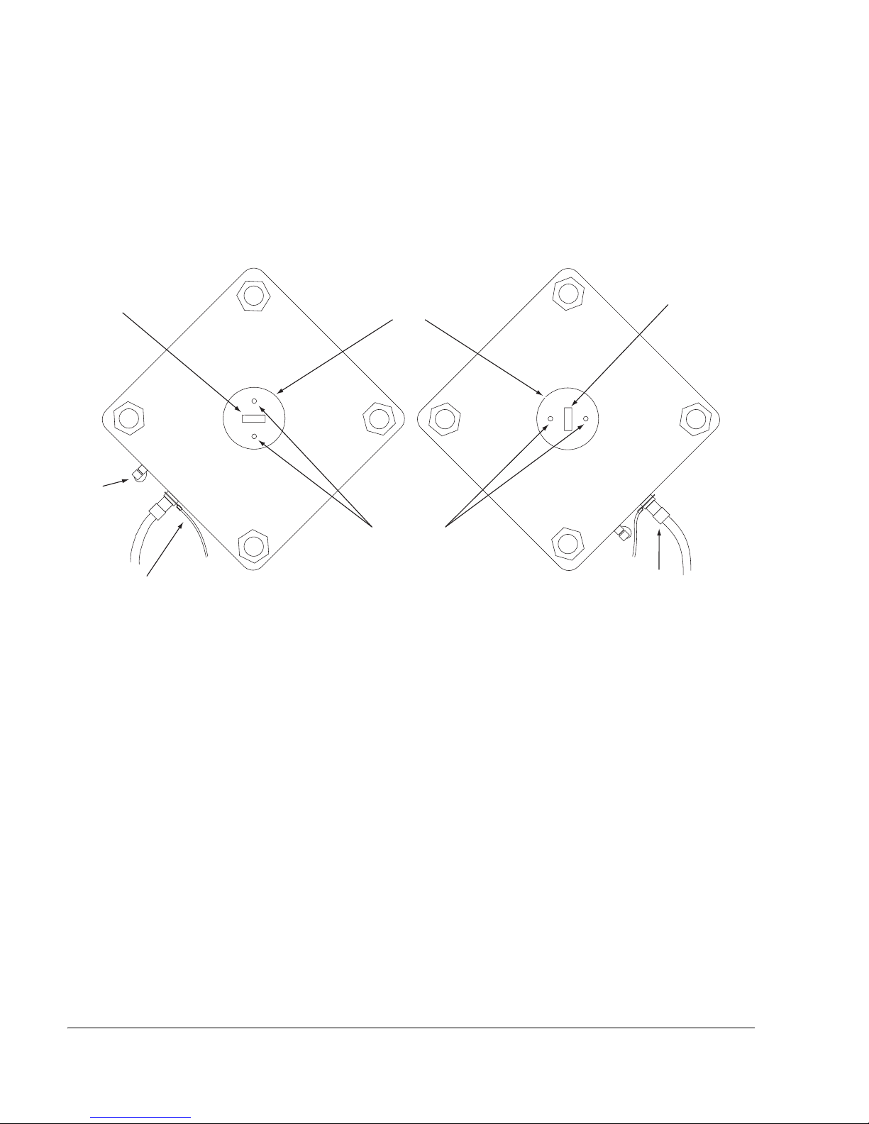
Correct selection for vertical or horizontal polarization is shown in Figure 6-3 on
page 6-4.
The polarization rotator is fixed by three metric Allen-head bolts. To adjust,
loosen the bolts, rotate, and re-fasten.
Page 60
Chapter 6. Installing the Antenna and ODU
6-4 Stratex Networks
Figure 6-3. ODU Orientation for Vertical or Horizontal Polarization
Figure 6-4 shows a close-up of the polarization rotator being released from the
vertical position (left) and rotated clockwise towards horizontal (right).
Figure 6-4. Close up of the Polarization Rotator
Face view of ODU
Vertical Polarization Horizontal Polarization
ODU cable
and connector
Grounding cable
Note orientation of
waveguide slot
RSSI
connector
Waveguide feed head
Locating holes for
polarization rotator pins
Note orientation of
waveguide slot
Page 61

Eclipse User Manual
260-668045-001 Rev 005 March 2004 6-5
Procedure
To install a direct-mount ODU:
1. Inspect the antenna mount and its polarization rotator.
2. Ensure the waveguide feed head, its O-ring, and the inner surfaces of the
polarization rotator are undamaged, clean, and dry.
3. Apply a thin layer of silicon grease around the O-ring.
4. Fully loosen the four nuts on the ODU mounting bolts.
5. Inspect the orientation of the waveguide slots.
The slots must be set for identical alignment when the ODU is rotated to its
end position.
6. Use gentle pressure to fit the ODU onto the mounting collar by inserting the
bolts through the receptor holes in the collar and then rotating the ODU
clockwise to bring the mounting bolts up against the slot ends.
7. Bring the ODU forward onto the collar and check for correct engagement of
the polarization locating pins with the ODU waveguide feed head.
Correct engagement allows the ODU to fit snugly against the face of the
collar. Ensure the ODU will no longer rotate.
8. Finger-tighten the four nuts, checking to ensure correct engagement of the
rotator locating pins with the ODU waveguide feed head.
9. Ensure the ODU bolt-down points are correctly seated and tighten the four
nuts with an open-ended 19mm (3/4 inch) spanner.
It is physically possible to mount the ODU upside down with the ODU
connectors facing upwards.
The ODU must be mounted with the connectors
facing down.
Forcing the ODU against the face of the collar during this process may damage to
the rotator locating pins and the face of the ODU waveguide feed head.
Ensure no impact damage occurs to the ODU feed head and polarization rotator
when bringing the ODU onto the collar.
Page 62
Chapter 6. Installing the Antenna and ODU
6-6 Stratex Networks
10. To remove an ODU, reverse this procedure.
Next Step
Grounding the ODU on page 6-6.
Grounding the ODU
The ODU cable kit includes a grounding cable, one end of which is fitted with a
large-diameter lug, and the other unterminated. The cable kit also includes a
stainless steel ground clamp to grip to a tower member to provide the grounding
point.
For installations where a lightning surge suppressor is also fitted at the ODU, this
grounding cable provides a common ground for the ODU and suppressor.
To ground the ODU:
1. Remove the top nut and washer from the bulkhead N-type connector on the
ODU.
2. Attach the lugged end of the ODU ground wire to the N-type connector. The
lug must be fitted between the jam nut and the washer and lock nut provided
on the N-type connector. Fasten the nut securely, but do not over-tighten as
thread damage can occur. Refer to Figure 6-5 on page 6-7.
When removing the ODU from its mount ensure the fastening nuts are fully
released. Otherwise it will not be possible to draw the ODU back sufficiently from
the collar to release the rotator locating pins from the ODU feed head.
The ODU must be grounded in accordance with these instructions. Failure to do
so may void the Stratex Networks warranty.
If the intended installation does not suit the standard installation kit items, ensure
appropriate alternatives are taken to the site. For example, a
round-tower-member adaptor to use in place of the angle-adaptor supplied in the
kit.
Do not attempt to remove the jam nut (the nut hard up against the ODU casting).
Page 63

Eclipse User Manual
260-668045-001 Rev 005 March 2004 6-7
3. Locate a position on the tower member for the ground clamp. This must be as
close as practical below the ODU for downward-angled positioning of the
grounding cable.
4. Before fastening the ground clamp to the tower, scrape any paint or oxidation
from the tower points of contact to ensure there will be good low-resistance
contact. Fasten the adaptor.
5. Cut the ground wire so that when connected to the ground clamp there is a
little slack in the wire.
6. Strip insulation back by 25 mm (1 in.), fit into ground clamp and firmly
secure the clamp.
7. Liberally apply conductive grease/paste around the tower-end ground clamp
to provide corrosion resistance.
Figure 6-5. Attachment of the ODU end of the ODU and Cable Ground
Wire
Next Step
Installing the ODU Cable on page 6-8
The grounding cable must not be run upward, or horizontal, or at a shallow
horizontal angle from the ODU as lightning takes the shortest path to ground.
Do not loop or spiral the wire.
Do not apply grease to the ODU end of the grounding cable. Refer to the topic
Weatherproofing the ODU Type N Connector on page 6-12.
Page 64

Chapter 6. Installing the Antenna and ODU
6-8 Stratex Networks
Installing the ODU Cable
This section addresses installation requirements for:
• ODU cable
• Type N cable connectors
• Weatherproofing of Type N connectors
• INU/ODU cable grounding
• Lightning impulse surge suppressor
• Indoor-unit to surge suppressor jumper cables
General Coaxial Cable Installation Guidelines
Some basic guidelines for installing coaxial cable:
• Take great care not to score the outer conductor of coaxial cable when removing
the jacket. For solid outer conductor cable use the cut-off and strip tool
specifically designed for the cable as a scored outer will weaken the cable and
may cause outer conductor to break or crack when the cable is flexed.
• For crimped connectors, use the crimp tool specifically designed for the
connectors and cable being used. Use of general purpose crimp tools may result
in sub-standard physical connections that may deteriorate over time and reduce
the quality of the electrical transmission.
• Plan the cable run ahead of time. Select a route that will provide adequate
protection for the cable once installed, will not impede access to the tower or
other services on the tower, and allows relative ease of running and fastening.
• Ensure the cable jacket is not damaged during the cable running. Provide
protection against sharp edges.
• Ensure the minimum bend radius for the cable is not infringed.
• Ensure the cable cannot flex in the wind. Where necessary use rod extension
kits to provide support over gaps in the cable path.
The ODU cable must comply with the Stratex Networks specification for Eclipse
and must be installed with its required lightning impulse surge suppressor(s) and
grounding kits. If not installed, or is incorrectly installed, the Stratex Networks
warranty may be voided.
Page 65

Eclipse User Manual
260-668045-001 Rev 005 March 2004 6-9
• Where possible avoid rebending of the cable, particularly multiple rebending.
This is especially relevant to solid outer cables.
• When tightening Type N connectors do so by hand only. Using tools such as
pliers to tighten an Type N connector could result in damage to the connector,
the equipment, or both.
ODU Cable Options
Two 50 Ohm cable types are available, the Belden type 9913F7, dual-shielded
(braid/tape) cable, and the Andrew BR-400C, Coral brand, solid outer conductor
cable.
ODU Cable Kits are offered for cable lengths of 80m, 150m, 300m and 400m
(260, 490, 980, 1310 ft). Each kit includes 3 Type N male connectors, plus
grounding kits, weatherproofing kits, and UV resistant cable-tie kits. The
included quantity of grounding kits, weatherproofing kits and cable-tie kits is
dependant on the length of ODU cable selected. For details, refer to the Required
Accessories section of the Installation Kits and Accessories Appendix; Appendix
C.
Belden 9913F7
The 9913F7 is a low-loss RG-8/U type with the following specifications:
• 10mm (0.405 inch) overall diameter
• Foam insulator with a PVC blend jacket
• Minimum bend radius: 77mm (3 inch)
• Nominal center conductor DC resistance: 1.1 ohms per 304m (1000 ft)
• Nominal outer shield DC resistance: 1.1 ohms per 304m (1000 ft)
• Nominal attenuation at 300 MHz: 2.4 dB per 30m (100 ft)
ODU cable kits for the Belden 9913F7 cable are in the process of being finalized.
The kits will be similar in content to the existing Andrew BR-400C kits. Contact
the Stratex Networks Help Desk for details.
Page 66

Chapter 6. Installing the Antenna and ODU
6-10 Stratex Networks
Andrew BR-400C
The Andrew BR-400C has the following specifications:
• 10.3mm (0.41 inch) overall diameter
• Foam insulator with a polyethylene jacket
• Minimum bend radius: 25.4mm (1 inch) final, 200mm (8 inch) running.
• Nominal center conductor DC resistance: 0.81 ohms per 304m (1000 ft)
• Nominal outer shield DC resistance: 1.78 ohms per 304m (1000 ft)
• Nominal attenuation at 300 MHz: 2.1 dB per 30m (100 ft)
ODU Cable Installation
• When running the cable to the ODU avoid excessive bending, and avoid using
a bending radius less than 200 mm (8 inch). A lesser bending radius may be
used for final fixing of the cable.
• Run the cable where it will be reasonably well protected and will not rub against
sharp edges or abrasive surfaces.
• Use one UV-resistant cable tie from the ODU cable kit at intervals of one meter
or less.
• Ensure the ODU cable cannot flex in the wind. This is especially relevant to
sections of the cable which loop unsupported between tower members or to the
ODU. Where necessary, use a rod support kit or similar to support the cable.
• Ensure there is adequate physical cable protection at locations where ice fall
from towers may occur.
Packs of UV resistant cable ties are included in the ODU cable Required
Accessories options. Packs of 50 are also available as an optional ODU
accessory.
Page 67

Eclipse User Manual
260-668045-001 Rev 005 March 2004 6-11
Jumper Cables
A jumper cable is required from the INU or IDU to the lower surge suppressor.
• For the INU (Eclipse Node) a 3m jumper cable is included with each RAC,
which is fitted with an SMA male connector at the RAC end, and a Type-N
female at the suppressor end. If the run length is greater than 3m, an extension
cable must be prepared to extend the jumper reach, using the ODU cable
(Belden 9913F7 or Andrew BR-400C) with Type N connectors fitted at both
ends.
• For the IDU (Eclipse Terminal) a jumper cable is not an included accessory, but
a 3m jumper is available as an optional IDU accessory. The cable is fitted with
a Type N male connector for the IDU end, and a Type N female connector at
the suppressor end. Otherwise, the Belden 9913F7 or Andrew BR-400C ODU
cable can be used to make up a suitable cable.
• Refer to the section Fitting the Lightning Surge Suppressor on page 6-14 for
jumper cable and connector details.
Fitting Type N Cable Connectors
Each ODU cable kit includes three male connectors for the ODU cable selected;
one for each end of the cable run, and one spare.
Additionally, each surge suppressor kit includes two Type N connectors, one
male and one female. These can be used with the ODU cable to make up an
extension jumper cable for an Eclipse Node installation (RAC jumper extension)
or to fabricate a complete jumper cable for an Eclipse Terminal installation.
Refer to the section Fitting the Lightning Surge Suppressor on page 6-14 for
details.
Refer to Appendix D for connector installation instructions. (For this release
of the Eclipse User manual, Appendix D does not include instructions for the
9913F7 connectors)
For the Andrew BR-400C the recommended Andrew cut-off/strip and crimp
tools must be used. These are listed as an ODU Accessories option in
Appendix A. Take care not to score the outer conductor when removing the
jacket.
Ensure the outer conductor of the Andrew BR-400C cable is not scored when
removing the cable jacket. Scoring may cause the outer conductor to crack or
break when the cable is flexed. Always use the correct Andrew cut-off/strip tool
for removing the jacket.
Page 68

Chapter 6. Installing the Antenna and ODU
6-12 Stratex Networks
Weatherproofing the ODU Type N Connector
This instruction applies to the Type N connector attaching to the ODU.
For installations where a lightning surge suppressor is fitted directly to the
ODU, refer to Fitting the Lightning Surge Suppressor on page 6-14.
A weatherproofing kit (PN
221213) is included as an ODU Cable Required
Accessory. It comprises six rolls of butyl mastic tape and three rolls of vinyl tape.
Special attention must be given to ensuring the butyl tape seals cleanly against
the start and end points, which will be the connector barrel at one end and the
cable sheath beyond the heat shrink at the other.
To weatherproof the ODU Type N Connector:
1. Ensure the ODU grounding cable has been fitted correctly.
2. Ensure the connector is firmly hand tightened and the assembly to be
protected, is dry and free from all grease and dirt. If in doubt, clean with a rag
lightly moistened with an alcohol based cleaner.
3. Pre-wrap the connector assembly using vinyl tape, beginning at the center of
the smooth barrel section of the ODU female connector through to 25 mm
(1 in.) past the connector (or heat-shrink) on the cable side. Use about 33%
overlay when wrapping. To avoid curl-back, do not stretch the tape too tightly
at the end point.
4. Wrap the assembly with the butyl tape:
• Begin wrap at the top, ground-lug-end of the smooth barrel section of the
ODU connector ensuring there is a full seal onto the bare metal.
• Continue to wrap with at least a 33% overlay to a point 25 mm (1 in.) past
the vinyl tape on the cable.
• Use your hands to lightly press down the tape overlays to ensure a full seal
at all points. Use a tear-off section of the butyl tape backing to protect your
hands from the mastic.
5. Wrap the butyl wrapping with vinyl tape. This helps to ensure good
amalgamation and adhesion of the butyl tape, and provides an added measure
of UV protection. Begin at the ODU end and continue to 25 mm (1 in.) past
the butyl tape on the cable. Do not stretch the last few turns to avoid curl-back.
In the following step it is important to leave at least half of the smooth barrel
section of the ODU connector clear of vinyl tape, as it is essential the butyl tape
has an area to direct-grip onto the bare metal of the connector barrel.The prime
purpose of the vinyl tape is not to weather-protect but to facilitate easy strip-back
of the weather protection (butyl tape) in the event an ODU requires changing.
Page 69

Eclipse User Manual
260-668045-001 Rev 005 March 2004 6-13
Installing ODU Cable Grounding Kits
Grounding kits are included in the ODU Cable Kits.
For tower (or mast) installations the ODU cable must be grounded:
• At the point where it comes on to the tower from the ODU, and
• At the point where it leaves the tower to go to the equipment building, and
• At not more than 25m (100 ft) intervals on the tower if the height on the tower
exceeds 50m, and
• At a point just prior to building entry.
Figure 6-6 shows an example of coaxial cable grounding.
A cable grounding kit is not required at the ODU as this is covered by the ODU
grounding kit, which fastens to the ODU cable connector assembly. Refer to
Grounding the ODU on page 6-6.
At non-standard installations, such as building tops or the sides of buildings,
follow the same general guidelines but where proper grounding points are not
provided these must first be installed. Refer to Stratex Networks’ Best Practices
Guide for examples.
Refer to Appendix D for ground kit installation instructions.
Figure 6-6. Example of coaxial cable grounding
Groundwire attachment
point to cable
Groundwire attachment
point to tower member
Page 70

Chapter 6. Installing the Antenna and ODU
6-14 Stratex Networks
Fitting the Lightning Surge Suppressor
The suppressor is an in-line PolyPhaser type MDSL-72-B2-NME. Depending on
the site location either one or two suppressors must be installed.
Non-Lightning Prone Sites
At sites where lightning strikes are a rare occurrence, one suppressor must be
installed in the ODU cable at a point just inside the building, or immediately
prior to building entry (between building entry and the cable ground kit). It must
not be installed at other than these two locations. Refer to Table 6-1 for details.
Lightning Prone Sites
At lightning prone sites, which may generally be categorized as sites that
experience more than 20 strikes per year, two suppressors must be installed, one
where the cable enters the building (as above), and one at the ODU.
Table 6-1. Surge Suppressor Installation at Building Entry
Location of Impulse
Surge Suppressor
Information
Installed inside the building The suppressor must be installed as close as practical to cable entry, and the
suppressor ground wire connected directly to master ground bar, or ground bar
extension. A normal cable grounding kit must be installed at the point of cable
entry outside the building.
Installed outside the building The suppressor ground must not double as the required building-entry cable
ground. A separate cable ground kit should always be installed.
The suppressor must be installed between the building and the cable ground kit.
The suppressor must be weatherproofed using materials from the weatherproofing
kit supplied with the suppressor. Refer to the section on suppressor
weatherproofing.
The suppressor must be grounded to the a ground bar installed just below the
cable point of entry to the building. This ground bar should be the master ground
for the station. If no ground bar exists at this point then it will be necessary to
install one. Refer to Stratex Network’s Best Practices Guide for details on station
grounding.
Page 71

Eclipse User Manual
260-668045-001 Rev 005 March 2004 6-15
The Surge Suppressor Kit includes the following items:
• Suppressor with ground nut, bolt and washer
• One Type N male and one Type N female connector (Connectors are ODU
cable-type specific)
• Grounding cable with one end lugged and the other end lugged or free
• Nut, bolt and washer for fastening the ground cable to the ground bar
• Weatherproofing kit. (This kit is being revised. The version shown in Figure 6-7
may not be the one supplied, however full instructions are supplied with the
kits)
Figure 6-7 shows the suppressor kit without the connectors.
Figure 6-7. Surge Suppressor Kit and Suppressor
If surge suppressors are not fitted, or are fitted incorrectly, the Stratex Networks
warranty may be voided.
Page 72

Chapter 6. Installing the Antenna and ODU
6-16 Stratex Networks
Suppressor Installation Procedure
Two procedures are described, one for the suppressor located at building entry,
which is required for all installations, and one for the ODU end of the cable,
which is a requirement for lightning prone sites.
At Building Entry
To install the lightning surge suppressor at building entry:
1. On the ODU side, trim the ODU cable to the point where the suppressor is to
be installed. Terminate the cable with an Type N male connector from the
ODU Accessories Kit.
2. Connect the suppressor to the ODU cable so that:
• The surge side faces the ODU and the equipment side faces the INU. The
surge side of the suppressor has a Type N female connector; the INU side a
Type N male.
• The ground wire attachment bracket must face downward to assist
weatherproofing integrity.
3. Connect from the suppressor to the indoor unit:
• For the Eclipse Node fit the RAC Jumper Cable to the INU side of the
suppressor. If the reach of the 3m jumper cable is insufficient an extension
cable must be constructed using a section of ODU cable with one Type N
male and one female connector.
• For the Eclipse Terminal make up a suitable cable using a section of ODU
cable with one Type N male and one Type N female connector, or select
the IDU 3m Jumper Cable from the surge suppressor accessories options.
4. Fit one end of the ground cable to the suppressor ground bracket using the
nuts and washers supplied.
5. If necessary, cut the ground wire so that there is a little slack in the wire when
it is connected to the ground bar. Fit and crimp a lug.
6. Attach the lug to the ground bar using the nut and bolt supplied.
Page 73

Eclipse User Manual
260-668045-001 Rev 005 March 2004 6-17
7. If the suppressor is located outside the building it must be weatherproofed,
which requires complete wrapping of the suppressor body and its connectors:
• Pre-wrap using vinyl tape beginning and finishing at points 25 mm (1 in.)
past the heat-shrink on the cable connectors (or 25 mm past the connector
barrel if no heat-shrink). Use a 33% overlay when wrapping. Ensure the
pre-wrap also covers the suppressor ground bracket and the ground wire
attachment. To avoid curl-back, do not stretch the tape too tightly at the
end point.
• Note that the prime purpose of the vinyl tape is not to weather-protect.
Rather it is facilitate easy strip-back of weather protection in the event a
suppressor requires inspection or changing. It is the butyl mastic tape that
provides the primary weather-protection and for this reason it must have
clear and clean start and end points onto the base surfaces, which is to the
cable and groundwire sheaths.
• Encase completely the vinyl-wrapped assembly with the butyl tape. This
may be achieved by a combination of wrapping and slabbing using wide
sections of the butyl tape. Ensure there is a full seal onto the cable and
groundwire sheaths, that is, beyond the vinyl wrap end-points. Lightly
firm over by hand to ensure a full seal at all points. Use a tear-off section
of the butyl tape backing to protect your hands. Check to see that there is
no possibility for water entry at any point in the wrapping before
proceeding with the next step.
• Post-wrap the assembly with vinyl tape. This helps to ensure good
amalgamation/adhesion of the butyl tape and provides an added measure
of UV protection. Do not stretch across sharp corners and edges to
avoid displacement of the butyl tape. Do not stretch the last few turns
to avoid curl-back.
8. Liberally apply copper-based grease around the nut/bolt/lug of the ground bar
end of the ground wire.
At the ODU
To install a lightning surge suppressor at the ODU:
For ease of installation it should be attached to the ODU together with the ODU
ground cable, and pre-weatherproofed before the ODU (with or without its
antenna) is hoisted into place. Refer to the example in Figure 6-8 on page 6-18.
1. Attach the ODU ground cable to the ODU, as detailed in Grounding the ODU
on page 6-6. This cable will provide the ground for the ODU and the
suppressor.
2. Attach the Type N male side of the suppressor to the ODU connector. Firmly
hand-tighten only.
3. Attach the ODU cable to the Type N female side of the suppressor. Firmly
hand tighten only.
Page 74

Chapter 6. Installing the Antenna and ODU
6-18 Stratex Networks
4. The suppressor must be weatherproofed, which requires complete wrapping
of the suppressor body and its connectors (refer to Figure 6-8):
• Pre-wrap using vinyl tape beginning at the center of the smooth barrel
section of the ODU female connector, and finishing at a point 25 mm
(1 in.) past the heat-shrink on the cable connector side (or 25 mm past the
connector barrel if no heat-shrink). Use a 33% overlay when wrapping.
Ensure the pre-wrap also covers the suppressor ground bracket and the
ground wire attachment. To avoid curl-back, do not stretch the tape too
tightly at the end point.
• Note that the prime purpose of the vinyl tape is not to weather-protect.
Rather it is facilitate easy strip-back of weather protection in the event a
suppressor requires inspection or changing. It is the butyl mastic tape that
provides the primary weather-protection and for this reason it must have
clear and clean start and end points onto the base surfaces, which are the
barrel of the ODU connector on one side and the cable and ground wire
sheaths on the other.
• Encase completely the vinyl-wrapped assembly with the butyl tape. This
may be achieved by a combination of wrapping and slabbing using wide
sections of the butyl tape. Ensure there is a full seal beyond the vinyl wrap
end-points. Lightly firm over by hand. Use a tear-off section of the butyl
tape backing to protect your hands. Check to see that there is no
possibility for water entry at any point in the wrapping before
proceeding with the next step.
• Post-wrap the assembly with vinyl tape. This helps to ensure good
amalgamation/adhesion of the butyl tape and provides an added measure
of UV protection. Do not stretch across sharp corners and edges to
avoid displacement of the butyl tape. Do not stretch the last few turns
to avoid curl-back.
Figure 6-8. Pre-Weatherproofing of a Suppressor at the ODU
Page 75

260-668045-001 Rev 005 March 2004 7-1
Chapter 7. Installing the INU and
INUe
Table 7-1 defines the Eclipse components.
Table 7-1. Eclipse Component Definitions
Component Definition
IDC Indoor Chassis. This is the chassis, with
backplane, into which the various plug-ins are
installed. The IDC is a 1RU chassis. The IDCe
(IDC expanded) is a 2RU chassis.
INU Intelligent Node Unit. Refers to a populated IDC,
an IDC which has mandatory and optional
plug-ins installed.
INUe INU expanded. Refers to a populated IDCe.
Eclipse Node Refers to the INU or INUe with ODU300 and/or
ODU 100. It provides a single platform solution
for up to three links in standard form (INU), and
up to six links expanded INUe). Plug-in cards
provide multiple link and tributary options.
Capacity extends from 4xE1/DS1 to 2xSTM1/
OC3. Modulation options extend from QPSK to
256QAM. Protection options support hot standby,
space diversity, frequency diversity, or ring.
Eclipse Terminal refers to the IDU with ODU 100. Two versions are
available; an 8x with capacity settings for 4x or
8xE1, and a 16x with settings for 4x, 8x, or 16x.
Modulation is QPSK only. A nonprotected option
is provided. Refer to Chapter 8.
Page 76
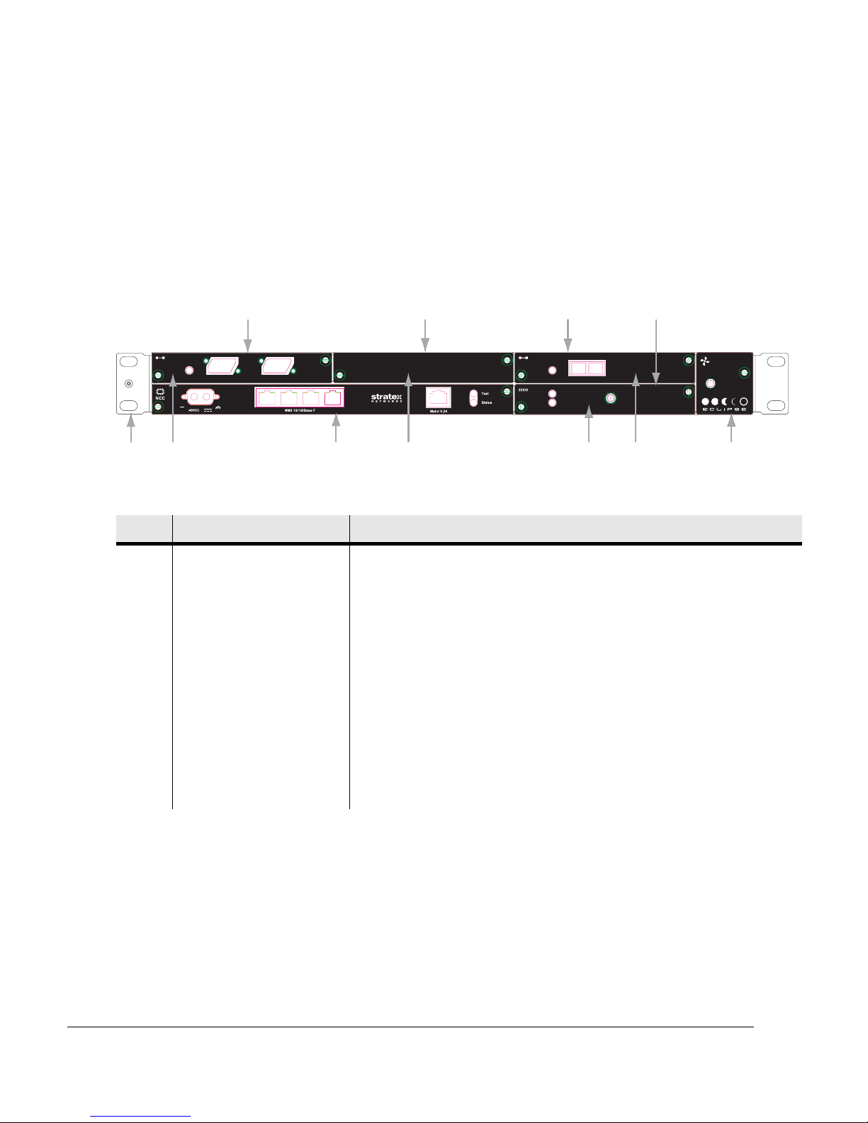
Chapter 7. Installing the INU and INUe
7-2 Stratex Networks
An INU comprises the IDC, NCC, FAN and optional RAC, DAC, AUX, NPC
plug-in cards. In Figure 7-1 the INU has three option cards fitted; a DAC 16x,
and two RAC 30s. The spare option slot is covered by a blanking panel.
The INUe is available where up to ten option slots are required. Additional node
capacity can also be achieved by tributary-cable interconnecting INUs or INUes
via DACs.
Figure 7-1. Typical INU Front Panel Layout
Table 7-2. INU Front Panel Descriptions
No Item/Label Description
1 Rack Ear and grounding
stud
Rack attachment bracket for the IDC. One ear has a combined ESD and IDC
grounding stud. The ears can be fitted either-side. The standard ears provide
flush-with-rack-front mounting. Ear options are available to provide
set-back mounting.
2 RAC 30 RAC 30 fitted in card slot 1.
3 NCC Mandatory Node Control Card. (Dedicated slot)
4 Blank Panel Blanking panel fitted to card slot 2.
5 RAC 30 RAC 30 fitted in card slot 4.
6 DAC 16x 16xE1/DS1 DAC fitted in card slot 3.
7 FAN Mandatory fan card. (Dedicated slot)
DAC 16x
Fault
FAN
To
ODU
RAC 30
On-Line
Status
DAC 1x155o
Status
Tx Rx
Optical 1
Status
Trib 1-8 Trib 9-16
DAC 16x
Fault
FAN
To
ODU
RAC 30
On-Line
Status
DAC 1x155o
Status
Tx Rx
Optical 1
Status
Trib 1-8 Trib 9-16
12
34
5
Slot 1 Slot 2 Slot 3
Slot 4
NCC FAN
-48VDC
Page 77

Eclipse User Manual
260-668045-001 Rev 005 March 2004 7-3
INU Installation Requirements
Unless otherwise mentioned, reference to the INU includes the INUe.
The INU and its associated dc power supply must be installed in a restricted
access area such as a secure equipment room, closet, or cabinet.
The INU requires 44.5 mm (1RU) of vertical rack space and 300 mm rack depth.
The INUe requires 89mm (2RU) vertical rack space. No space above or below is
required for ventilation purposes.
The INU requires unobstructed air passage to each side for ventilation purposes.
There must be a minimum of 50 mm (2 in.) of side spacing to any rack panels,
cable bundles or similar.
The INU is specified for a maximum ambient temperature (Tmra) of +55°
Celsius (131° Fahrenheit). If the INU is installed in a closed or multi-unit rack
assembly, the operating ambient temperature of the rack environment may be
greater than room ambient. The maximum ambient temperature (Tmra) of +55°
Celsius is the figure to apply to the immediate operating environment of the INU,
which if installed in a rack, is the ambient applying within the rack.
Ensure that by adding an INU or INUs to a rack that the loading does not impact
the mechanical stability of the rack.
The INU has the +ve pin on its dc power supply connector fastened directly to
the chassis. It must be used with a -48 Vdc power supply which has a +ve earth;
the power supply earth conductor is the +ve supply to the INU. There must be no
switching or disconnecting devices in this earth conductor between the dc power
supply and the point of connection to an INU.
The INU must be installed in the same premises as its dc power supply and be
located in the same immediate area (such as adjacent racks or cabinets) as any
other equipment that is connected to the same dc power supply.
The dc power supply must be UL or IEC compliant for a -48 Vdc SELV output
(60 Vdc maximum). Check to ensure that connection of an Eclipse system to an
existing dc supply does not overload the supply, circuit protection devices and
wiring. Where a new dc power supply is to be installed for an Eclipse Node, the
power supply must be rated to supply:
• 12.5A. for the INU
• 25A for the INUe
Page 78
Chapter 7. Installing the INU and INUe
7-4 Stratex Networks
The INU must be grounded to the station or master ground, which must be the
same ground as used for the dc power supply. Normally this is achieved by
grounding the INU to the grounding bar in its equipment rack or frame. This bar
is most often located to one side of the rack or at rack top or bottom. In turn, the
grounding bar is grounded to the station ground.
Installing an INU
To install an INU:
1. Check that the front panels of the plug-in cards are flush-fitted (not
protruding) and held secure by their fasteners. Ensure that unused slots are
covered by blanking panels.
2. Fit the rack mounting ears to the IDC with the grounding stud to left or right
side for the most direct ground wire path to the grounding bar.
3. Locate the INU in the equipment rack and secure it using four No.12 Phillips
dome-head screws from the IDC installation kit.
4. Ground the INU from the grounding stud to the rack/frame ground bar using
a length of 4 mm
2
(#14) green PVC insulated stranded copper wire with a
suitably sized ground lug at each end.
5. If the equipment rack/frame requires grounding, use 16 mm
2
(#6) wire from
its ground bar to the station ground.
Do not assume that an existing rack or mounting frame is correctly grounded.
Always check the integrity of the ground connections, which must include a
check through to the master ground for the station, which should be located at
the point of cable entry to the equipment building.
Always check the integrity of the dc power supply and grounding circuits right to
their sources.
The standard ears provide flush-with-front mounting. Options are available to
provide set-back mounting.
The ground wire and lugs must be supplied by the installer.
Page 79

Eclipse User Manual
260-668045-001 Rev 005 March 2004 7-5
6. Fit the supplied RAC jumper cable between the RAC and lightning impulse
surge suppressor. Secure the cable within the rack/frame using cable ties or
similar.
The standard jumper cable is a 3m length of RG 142 cable with an SMA
right-angle male connector fitted at one end and an N-type female at the other.
To extend the jumper length, refer to the topic Fitting the Lightning Surge
Suppressor on page 6-14 in Chapter 6.
7. Fit the DAC tributary cables.
8. Prepare,
but do not connect, the power cable supplied in the IDC Installation
Kit. It is supplied with the connector fitted at one end, and wire at the other.
Refer to Figure 7-2. The connector plugs into the NCC.
The wires are 4 mm
2
(14 gauge) and nominally 5m long. Run the cable
through to the power pick-up point, which will normally be a circuit breaker
panel in the rack. The circuit breaker should have a capacity of 12 amps for
the INU, and 25 amps for the INUe. The red wire must be connected to +ve/
ground, the black wire to the -ve supply.
• The NCC and NPC are fitted with a fast acting 25A fuse.
• The power input is polarity protected.
Figure 7-2. Power cable and connector
The serial production NCC (NCC V2) is fitted with a 25A fast acting fuse on the
PCB. Early production NCCs are fitted with a front panel fuse/switch, fitted with a
12.5A slow-blow fuse.
Page 80

Chapter 7. Installing the INU and INUe
7-6 Stratex Networks
Next Step
If all plug-in cards are correctly installed, the Eclipse Node is ready for power-on
and antenna alignment. Refer to Chapter 6 Antenna Alignment in this volume.
Measure the voltage on the dc power connector before it is connected to the INU
or IDU. The voltage should be -48 Vdc (+ve is earth).
Limits are -40.5 to -60 Vdc.
This product meets global product safety requirements for safety extra-low
voltage (SELV) rated equipment where the input voltage MUST be 48V nominal,
60V maximum. The power supply supplying the Eclipse equipment must be
guaranteed to remain within the safety extra-low voltage (SELV) limits in the event
of a single internal fault.
Once powered up the ODU(s) will be transmitting with the pre-configured or
ex-factory frequency and power settings, unless the transmit mute option has
been invoked as the start-up default. Unless customer specified, this start-up
mute will be included on all INUs shipped ex-factory. If not muted and if frequency
and/or power settings are not correct for the site, interference may be caused to
other links in the same geographical area.
Page 81
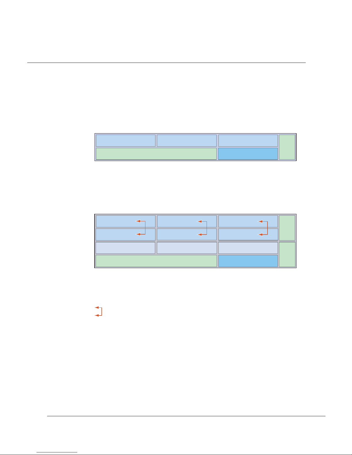
Eclipse User Manual
260-668045-001 Rev 005 March 2004 7-7
Installing Plug-in Cards
The IDC has four universal slots and two dedicated slots. The IDCe has six
universal slots, three restricted slots and 4 dedicated slots. Refer to Figure 7-3 for
slot loading details. A populated IDC/IDCe is called an INU/INUe.
Figure 7-3. Slot Numbering for INU and INUe
Installing or changing out a card is a simple plug-in process.
• Cards are hot-swappable. The INU does not need to be powered down. Bear in
mind that removal of an in-service option card will interrupt its traffic. Removal
of the NCC will affect all traffic, unless protected by an NPC.
• When removing a RAC from a powered INU, always disengage the RAC from
the backplane before disconnecting its ODU cable. Similarly, before inserting
a RAC, always reconnect the ODU cable before engaging the backplane.
INU
INUe
Fan
Slot 1
Slot 2
Slot 3
NCC
Slot 4
Fan
Slot 1
Slot 2
Slot 3
Slot 4
Fan
Slot 7
Slot 5
Slot 6
Slot 9
Slot 8
NCC
Slot 10
Slots 1, 2, 3, 4 are universal: any RAC, DAC or AUX plug-in
Slot 4 is NPC or universal: NPC or any RAC, DAC, AUX
NCC and FAN slots are dedicated
Slots 1, 2, 3, 4, 5, 6 are universal: any RAC, DAC or AUX plug-in
Slots 7, 8, 9 are restricted: any DAC or AUX
Slot 10 is restricted: NPC option only
NCC and FAN slots are dedicated
For protected operation the RACs must be paired
in the positions indicated by the arrows
Page 82

Chapter 7. Installing the INU and INUe
7-8 Stratex Networks
• When swapping or installing new cards up to 60 seconds may be required for
the INU to reflect its revised system status via the front panel LEDs and in
Portal.
• When installing a card ensure its backplane connector is correctly engaged
before applying sufficient pressure to bring the card panel flush with the IDC
front panel.
• Cards and blanking panels are held in place by captive finger-screws. Ensure
the finger screws are fastened as failure to do so may compromise EMC
integrity.
• Keep any removed blanking panels, for future use.
Basic Rules for Installing Plug-in Cards
• The NCC, FAN and NPC cards have dedicated slots.
• The RAC, DAC and AUX cards can be fitted in any of the universal slots in an
INU or INUe.
• An INU can be fitted with a maximum of three RACs for three non-protected
links, or one protected/diversity link plus one non-protected link.
• An INUe can be fitted with a maximum of six RACs for:
• Six non-protected links or,
• One protected/diversity link plus four non-protected links or,
• Two protected/diversity links and two non-protected or,
• Three protected/diversity links.
All slots must be filled with either a card or a blanking panel. Failure to do so will
compromise EMC integrity and distribution of cooling air from the FAN.
Never disconnect or reconnect an ODU cable to a RAC without first turning the
power off to the INU or withdrawing the RAC from its backplane. Failure to comply
with this may damage the equipment and any resultant repair action will not be
covered by warranty.
Always wear proper ESD grounding straps when changing or handling the plug-in
cards and avoid hand contact with the PCB back-plane and top-plane. Connect
your ESD grounding strap to the combined ESD and ground connector on the
INU rack ear. Spare plug-in cards or cards to be returned for service must be
enclosed in an anti-static bag. When removing a card from the anti-static bag for
installation in an INU, or placing a card in a bag, do so at the INU and only when
connected to the INU via your ESD grounding strap.
Page 83

Eclipse User Manual
260-668045-001 Rev 005 March 2004 7-9
• DACs can be fitted singly or in combination to provide a mix of interface types
and capacities, providing they have a common backplane configuration. The
backplane can be set for E1, DS1, E3, DS3, or STM1/OC3. Mux version DACs
allow a mix of interfaces from a common E1 or DS1 backplane configuration.
• When installing a 16xE1/DS1 DAC use slots to the right-side of the INU or
INUe for easier cable management. If installed left-side, the heavier tributary
cables for the DAC 16x may restrict easy access to cards installed to their right.
• Line (interface) protection can be provided for paired E3/DS3 and STM1
electrical DACs using BNC Y-cable options.
• Line (interface) protection can be provided for paired STM0 optical DACs
using optical Y-cable options.
• Only one AUX can be installed per INU or INUe.
• Only one NPC is required to provide the NCC protection option.
• The maximum through capacity of an Eclipse Node comprising one INU or
INUe is:
• 100xE1, or
• 128xDS1, or
• 8xE3, or
• 6xDS3, or
• 2xSTM1/OC3
To achieve greater node capacity, two or more INUs or INUes must be
interconnected via a DAC option with tributary cables.
• Except for the NCC (unless protected by an NPC), cards are hot-installable and
swappable - there is no requirement to power down an operational node. Bear
in mind that any removal of an in-service card will affect traffic.
• Never disconnect or reconnect an ODU cable to a RAC without first turning the
power off to the INU or withdrawing the RAC from its backplane. Failure to
comply with this may damage the equipment and any resultant repair action will
not be covered by warranty.
• Never install, change or remove a card without first connecting yourself to the
INU with an ESD grounding cable. Failure to do so may cause ESD damage to
the cards.
Page 84

Chapter 7. Installing the INU and INUe
7-10 Stratex Networks
Plug-in Cards and Interfaces
The plug-in cards, their interfaces and LED indications are described in the
following order: NCC, FAN, RAC, DAC, AUX, NPC.
NCC
The NCC plugs into a dedicated slot in the IDC or IDCe. Although the NCC is
field replaceable, it is not hot swappable unless an NPC is installed. Otherwise its
removal will interrupt all traffic through the INU.
Functions
The NCC provides the following major functions:
• TDM bus clock and signaling distribution for the INU
• Microprocessor for control and management
• DC/DC converter to supply power to other plug-ins in the INU
Front Panel User Interfaces
• Battery input (-48 Vdc)
• 4 port Ethernet connector assembly (NCC V2) for ProVision and/or Portal
access
• Serial V.24 interface for Portal access
• LED status indicators
Figure 7-4 on page 7-11 shows the NCC front panel layout (NCCv2).
Table 7-3 on page 7-11 describes the front panel layout.
Table 7-4 on page 7-12 lists 10/100Base-T connector pinouts.
Table 7-5 on page 7-13 lists the V.24 Maintenance connector pinouts.
IDC cards must be withdrawn and inserted using their finger-grip fasteners/pulls.
Never withdraw or insert using attached cables, as damage to the card connector
and its PCB attachment may occur. If not complied with the Stratex Networks
warranty may be voided.
Always wear proper ESD grounding straps when changing or handling the plug-in
cards and avoid hand contact with the PCB back-plane and top-plane. Connect
your ESD grounding strap to the combined ESD and ground connector on the
INU rack ear. Spare plug-in cards or cards to be returned for service must be
enclosed in an anti-static bag. When removing a card from the anti-static bag for
installation in an INU, or placing a card in a bag, do so at the INU and only when
connected to the INU via your ESD grounding strap.
Page 85
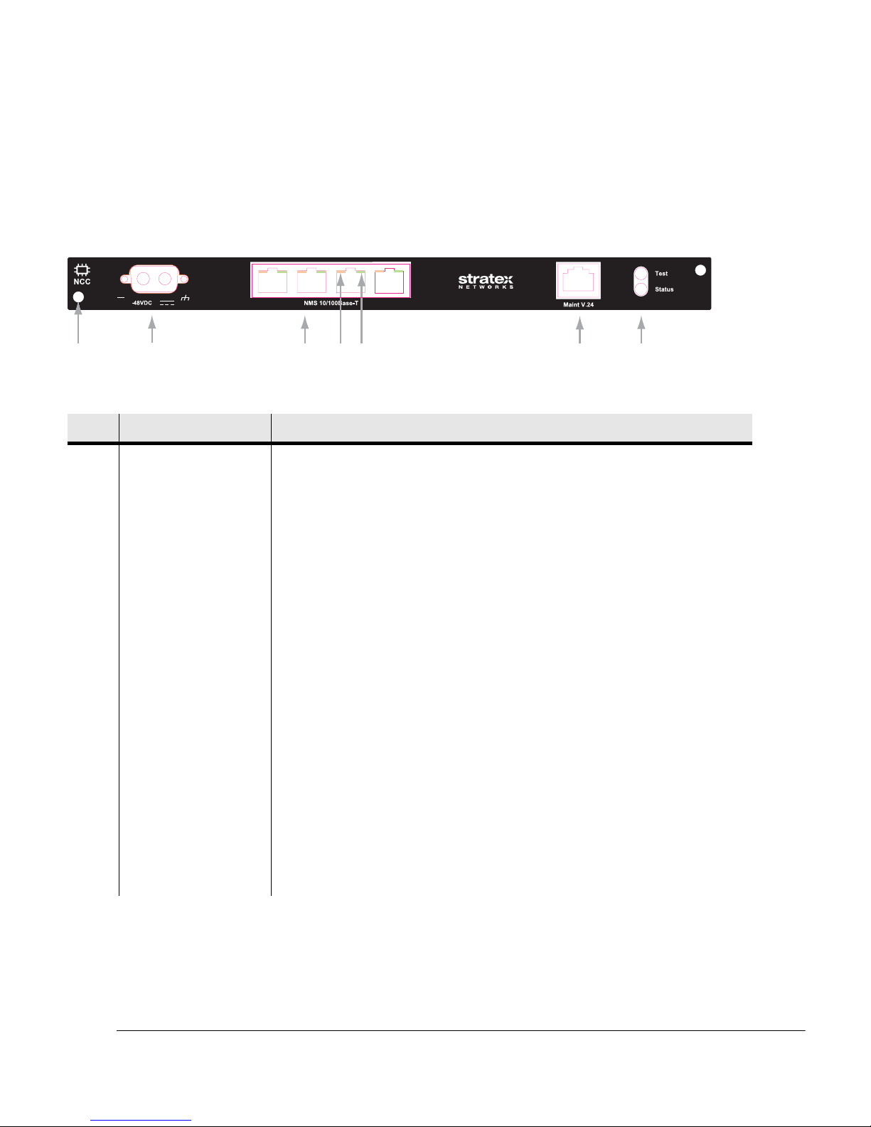
Eclipse User Manual
260-668045-001 Rev 005 March 2004 7-11
PCB Accessed User Interfaces
• A fast acting 25A tubular ceramic fuse (NCCv2)
• CompactFlash card
Figure 7-4. NCCv2 Front Panel Layout
Table 7-3. NCCv2 Front Panel Descriptions
No Item/Label Description
1 Card fastener Finger-grip screw-type fastener and card pull (2).
2 -48VDC 2-pin polarized power connector with screw fasteners.
3 NMS 10/100Base-T Assembly of four RJ-45 connectors provides an Ethernet hub for network
management access. ProVision and/or Portal login to these ports requires entry
of the IP address for the INU. Ports are also used to provide NMS connectivity
to co-located Eclipse INUs and other Stratex and third party radios.
4 Ethernet orange LED Orange flashing LED indicates Ethernet receive activity. Off indicates no
receive activity. Fitted to each RJ-45 connector.
5 Ethernet green LED Green LED indicates connection of an Ethernet link. Off indicates no Ethernet
link connection. Fitted to each RJ-45 connector.
6 Maint V.24 RJ-45 connector provides a V.24 serial interface option for Portal. A default IP
address means knowledge of the INU IP address is not required at login.
7 Test LED Test LED provides indications of:
Off:
Green:
Red/Green flashing:
INU power off
Normal operation
INU is in a test/diagnostic mode, for
example, loopbacks are set
Status LED Status LED provides indications of:
1
2
3
45
67
-48VDC
Page 86

Chapter 7. Installing the INU and INUe
7-12 Stratex Networks
NMS 10/100Base-T Connector
Pin assignments represent standard Ethernet LAN cable wiring and are identical
for each of the three RJ-45 connectors in the 10/100Base-T assembly. Different
length ‘straight’ Ethernet cables are included as optional accessories.
Table 7-4. RJ-45 NMS Ethernet Connector Pin Assignments
Off:
Green:
Green/Red flashing:
Red:
INU power off
Normal operation
Configuration not supported or software /
hardware incompatible
Critical alarm
No Item/Label Description
The NCC Ethernet ports auto-resolve for straight and crossover cables (Mdi or
MdiX). Either cable type can be used.
Pin Function
1 Ethernet transmit data +
2 Ethernet transmit data -
3 Ethernet receive data +
4 Not used
5 Not used
6 Ethernet receive data -
7 Not used
8 Not used
Page 87
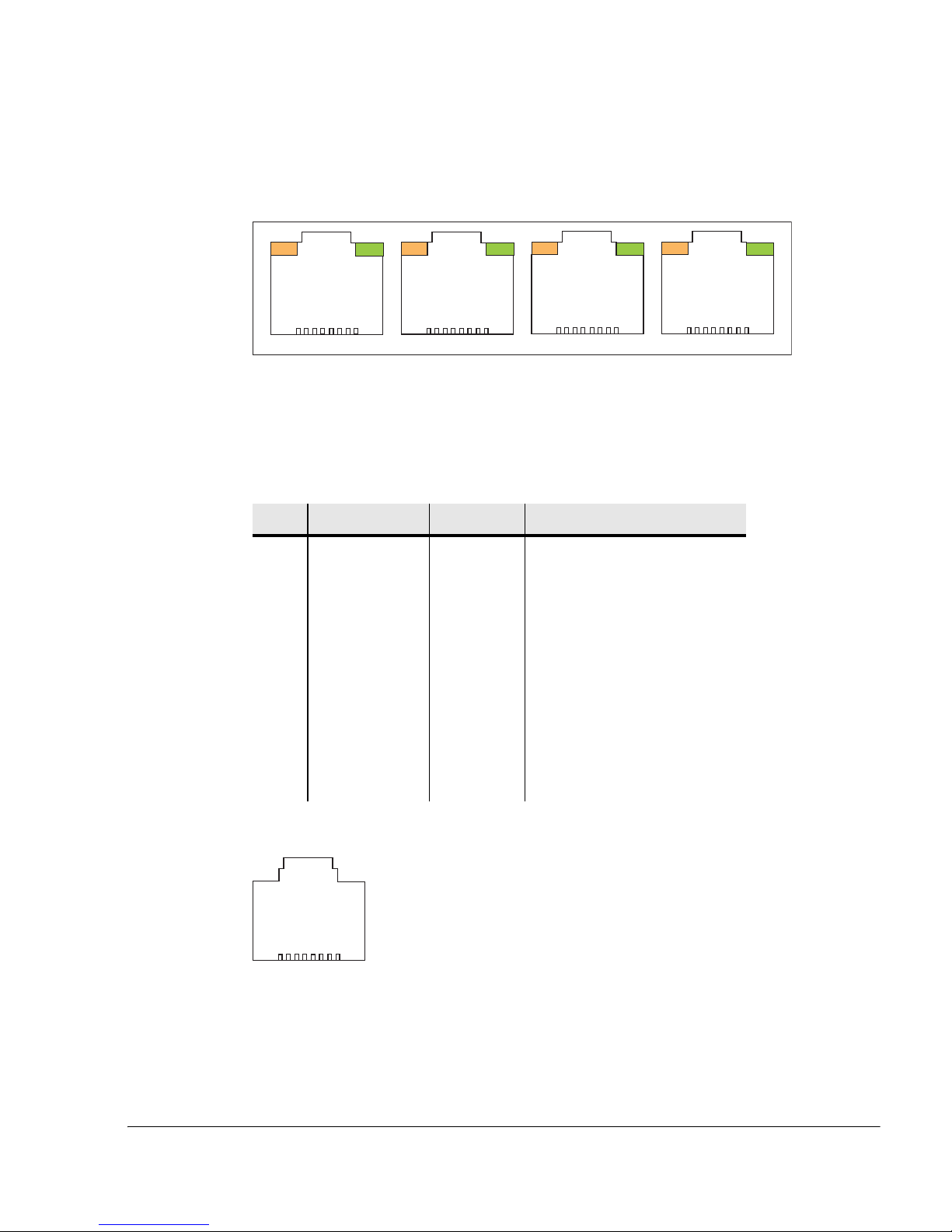
Eclipse User Manual
260-668045-001 Rev 005 March 2004 7-13
Figure 7-5. RJ-45 Connector Assembly
Maintenance V.24 Connector
The V.24 connector provides serial data access for Portal. One RJ-45 to DB-9
V.24 Maintenance Cable is included with every IDU.
Table 7-5. RJ-45 V.24 Connector Pin Assignments
Figure 7-6. Maintenance V.24 RJ-45 Connector
1
23
1
8
18
1
8
1
8
Orange
Green
4
Pin Signal Name Direction Function
1 DSR/RI In Data Set Ready/Ring Indicator
2 CD In Carrier Detect
3 DTR Out Data Terminal Ready
4 GND System Ground
5 RXD In Receive Data
6 TXD Out Transmit Data
7 CTS In Clear to Send
8 RTS Out Request to Send
1
8
Page 88
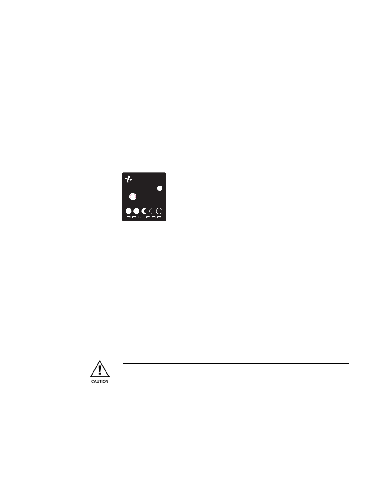
Chapter 7. Installing the INU and INUe
7-14 Stratex Networks
FAN
The FAN card plugs into a dedicated slot. One is required for the IDC, two for the
IDCe. The FAN is field replaceable and can be hot swapped. Removal will not
interrupt user traffic.
The FAN module holds two long-life axial fans. Fan operation is temperature
controlled and is performance monitored by the NCC. Under normal conditions
one fan operates, cycled between the two fans. Both fans will operate if the first
fan fails to keep the temperature below a preset threshold. Refer to Figure 7-7.
The LED is off (no illumination) for normal operation. Red indicates a critical
FAN alarm.
Figure 7-7. Eclipse Fan Card
RAC
The RAC is the intermediary between the TDM backplane and ODU. Different
versions provide support for capacity and bandwidth options up to 2xSTM1/
OC3. Currently available are the RAC 30 and RAC 10.
Up to three RACs can be fitted in the IDC universal slots, and six in the IDCe.
They can be used to support non-protected or protected links where links can be
of the same or different capacity and on the same or different frequency bands.
Two identically configured RACs/ODUs are used for hot-standby protected or
diversity operation.
RACs are not frequency dependent.
The RAC is field replaceable and hot swappable. But when hot-swapping always
withdraw the card from its backplane before disconnecting the ODU cable.
Similarly, always reconnect the ODU cable before reinserting the card.
FAN
Never disconnect or reconnect an ODU cable to a RAC without first turning the
power off to the INU or withdrawing the RAC from its backplane. Failure to
comply with this may damage the equipment and any resultant repair action will
not be covered by warranty.
Page 89

Eclipse User Manual
260-668045-001 Rev 005 March 2004 7-15
RAC 30
RAC 30 is the intermediary between the digital baseband and ODU 300 for
capacities from 4xE1/DS1 to STM1/OC3, with bandwidths up to 28 MHz.
Table 7-6 lists the capacity, modulation, and bandwidth options. Depending on
capacity, modulation rates are programmed for QPSK, 16-QAM, 32QAM, or
128-QAM.
Table 7-6. RAC 30 capacity, modulation, and bandwidth options
Capacity Modulation Bandwidth
4/8/16xE1/DS1 QPSK 7, 14, 28 MHz
4/8/16/32xE1 16-QAM 14, 28 MHz
1/2xE3 16-QAM 14, 28 MHz
3xE3 32-QAM 28 MHz
4xE3 128-QAM 28 MHz
STM1 128-QAM 28 MHz
4/8/16/28xDS1 16-QAM 2.5, 5.0, 10, 20 MHz
8/16/28/56xDS1 32-QAM 3.75, 5, 10, 20 MHz
DS3 16-QAM 10 MHz
1/2xDS3 32-QAM 10, 20 MHz
3xDS3 128-QAM 30 MHz
OC3 128-QAM 30 MHz
Page 90
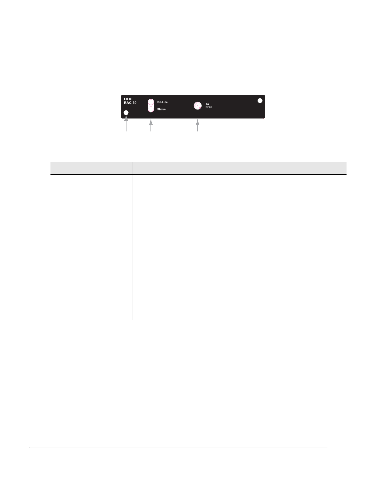
Chapter 7. Installing the INU and INUe
7-16 Stratex Networks
Figure 7-8 shows the front panel layout. Table 7-7 describes the front panel
layout.
Figure 7-8. RAC 30 Front Panel Layout
Table 7-7. RAC 30 Front Panel Description
12 3
No Item/Label Description
1 Card fastener Finger-grip screw-type fastener and card pull (2).
2 On-Line LED On-Line LED provides indications of:
• Off:
•Green:
•Red:
INU off-line or ODU transmit muted
RAC is online with transmit or receive active
1
No receive signal from the ODU
1. The transmit active or receive active criteria are to support all configurations including diversity where one RAC is transmitting
and receiving and the other receiving only.
Status LED Status LED provides indications of:
• Off:
•Green:
•Red/Green
flashing:
•Red:
INU power off
Normal operation
Configuration not supported, software / hardware incompatible
or in diagnostic mode
2
Critical RAC or ODU alarm
3
2. Includes situations where the slot configuration does not support the card, where the card requires a later/different version of
software or where the card has been set for an IF loopback.
3. Includes alarm situations caused by component or power supply failure and transmit or receive path failure.
3 ODU connector SMA type for ODU jumper cable connection
Page 91

Eclipse User Manual
260-668045-001 Rev 005 March 2004 7-17
RAC 10
RAC 10 has an identical front panel layout to RAC 30.
RAC 10 is the intermediary between the digital baseband and ODU 100 for
capacities from 4xE1/DS1 to 16xE1/DS1, QPSK modulation only.
RAC 10 is intended for low capacity linking to either an Eclipse Terminal
comprising the IDU and ODU 100 for non-protected operation, or to another
Eclipse Node for protected or diversity operation, which requires installation of
two RAC 10s and two ODU 100s per end.
An IDC or IDCe can be fitted with a mix of RAC 10s and RAC 30s.
LED indications are as for RAC 30.
DAC
The DACs provide the intermediary between the customer interface and the
digital backplane.
Different DACs support different circuit rates and formats. Currently available
are the DAC 4x, DAC 16x, DAC 1x155o and DAC ES.
DACs can be installed in any of the universal slots in an IDC or IDCe, and also in
restricted slots in the IDCe. DACs are field replaceable and hot-swappable.
DAC 4x
DAC 4x provides up to 4xE1 or 4xDS1 tributaries. Each tributary is interfaced
via an RJ-45 connector, and tributary cable sets are available as accessories to
provide:
• RJ-45 to BNC male unbalanced.
• RJ-45 to RJ-45 balanced, straight or crossover.
• RJ-45 to unterminated for balanced connection to wire wrap or punch-down
insulation displacement blocks.
For cable options, refer to DAC Accessories in Appendix C.
For trib connector and trib cable pin-out data, refer to Appendix E.
The DAC 4x can plug into any of the IDC or IDCe universal slots and also in the
restricted slots in the IDCe.
Page 92
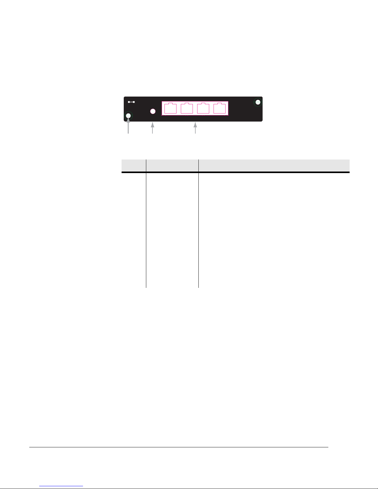
Chapter 7. Installing the INU and INUe
7-18 Stratex Networks
Figure 7-9 shows the DAC 4x front panel layout. Table 7-8 describes the DAC 4x
front panel layout.
Figure 7-9. DAC 4x front panel layout
Table 7-8. DAC 4x Front Panel Description
No Item/Label Description
1 Card fastener Finger-grip screw-type fastener and card pull (2).
2 Status LED Status LED provides indications of:
Off INU power off
Green Normal operation
Red/Green
flashing
Configuration not supported,
software / hardware incompatible or
in diagnostic mode
1
1. Includes situations where the slot configuration does not support the card, where the card requires
a later/different version of software or where the card has been set for a tributary loopback.
Red Critical alarm
2
2. Indicates a traffic-affecting hardware failure.
3 Trib. connector
assembly
4xRJ-45 type connectors for tributary cable connection
Status
14
12 3
Trib 1-4
DAC 4x
Page 93

Eclipse User Manual
260-668045-001 Rev 005 March 2004 7-19
DAC 16x
DAC 16x provides up to 16xE1 or 16xDS1 tributaries. Two Mini RJ-21
connectors provide the customer interface, and tributary cable sets are available
as accessories to provide:
• Mini RJ-21 to BNC male (16) unbalanced. Provides connection for up to 8 tribs.
• Mini RJ-21 to RJ-45 (8) balanced, straight or crossover. Provides connection
for up to 8 tribs.
• Mini RJ-21 to unterminated for balanced connection to wire wrap or
punch-down insulation displacement blocks. Provides connection for up to 8
tribs.
For cable options, refer to DAC Accessories in Appendix C.
For trib connector and trib cable pin-out data, refer to Appendix E.
The DAC16x can plug into any of the IDC or IDCe universal slots and also in the
restricted slots in the IDCe. However, because the tributary cables extend to the
right (viewed from front), it is recommended that slots to the right side of the
IDC or IDCe are used to avoid impairing access to other cards.
Standard tributary cable sets for DAC 16x have the cables exiting to the right of
their RJ-21 connectors when viewed from the front.
Page 94
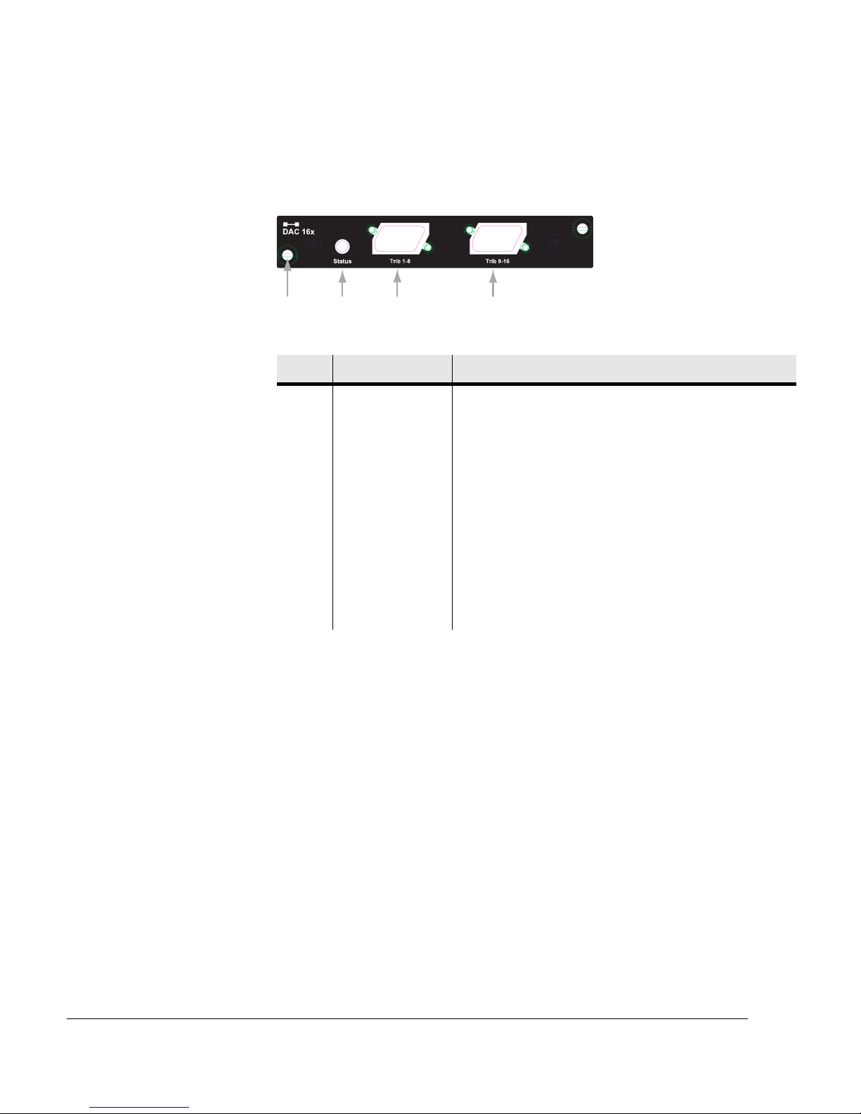
Chapter 7. Installing the INU and INUe
7-20 Stratex Networks
Figure 7-10 shows the DAC 16x front panel layout. Table 7-9 describes the
DAC 16x front panel.
Figure 7-10. DAC 16x Front Panel Layout
Table 7-9. DAC 16x Front Panel Description
No Item/Label Description
1 Card fastener Finger-grip screw-type fastener and card pull (2).
2 Status LED Status LED provides indications of:
Off INU power off
Green Normal operation
Red/Green
flashing
Configuration not supported,
software / hardware incompatible or
in diagnostic mode
1
1. Includes situations where the slot configuration does not support the card, where the card requires
a later/different version of software or where the card has been set for a tributary loopback.
Red Critical alarm
2
2. Indicates a traffic-affecting hardware failure.
3, 4 Trib. connector RJ-21 type connectors for tributary cable connection
123 4
Page 95
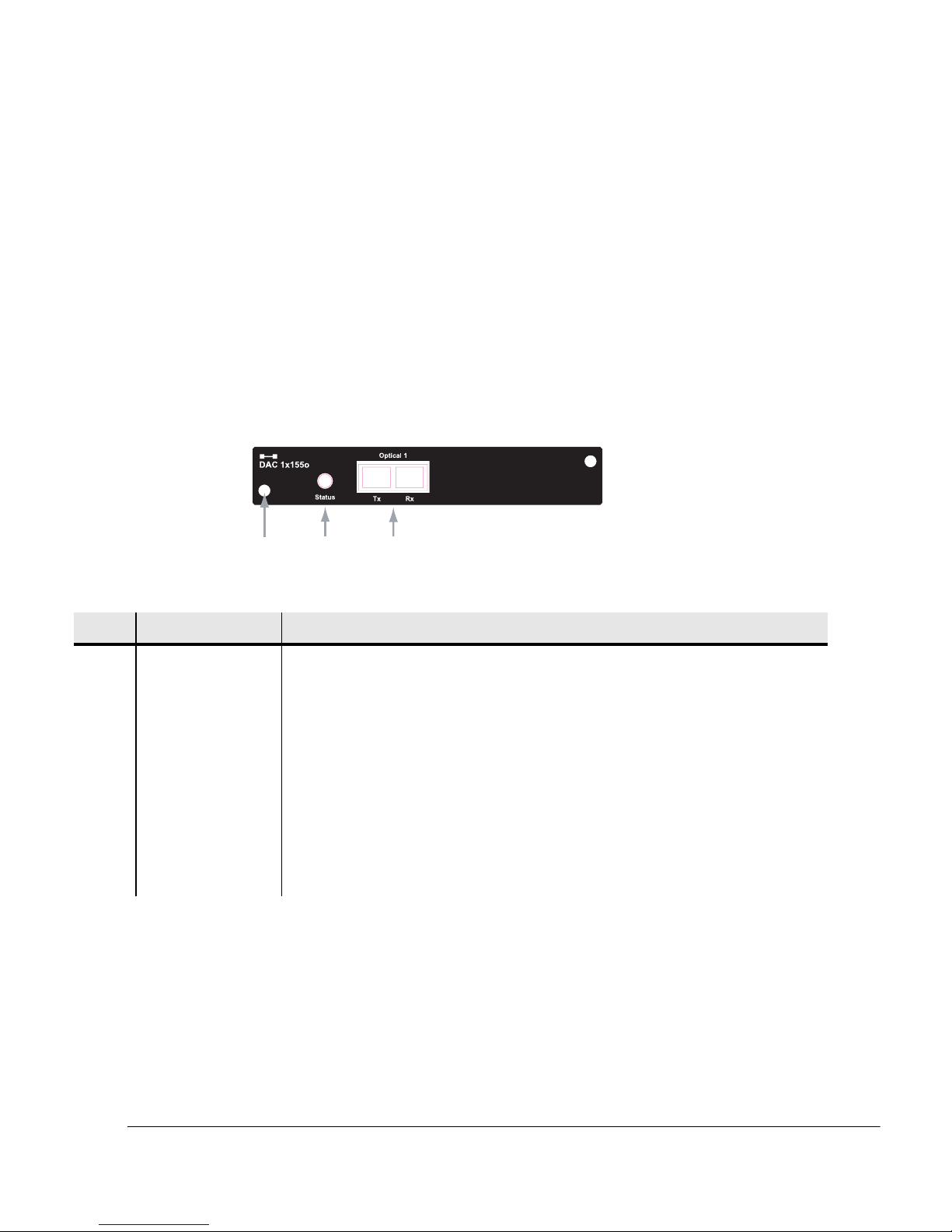
Eclipse User Manual
260-668045-001 Rev 005 March 2004 7-21
DAC 1x155o
DAC 1x155o provides access for one STM1/OC3, 155 Mbps tributary
connection. The connector is an SC optical type. Tributary cable options include
extension to SC or FC connectors. Where protection of the DAC is required (line
protection), two DAC 1x155o cards can be installed and splitter Y-cables fitted to
provide extensions to SC, FC or LC connectors. Refer to DAC Accessories in
Appendix C for cable options.
DAC 1x155o is field replaceable and hot-swappable, and can plug into any of the
four option slots in the IDC or IDCe.
Figure 7-11 shows the DAC 1x155o front panel layout. Table 7-10 describes the
DAC 1x155o front panel.
Figure 7-11. DAC 1x155o Front Panel Layout
Table 7-10. DAC 1x155o Front Panel Descriptions
1
23
No Item/Label Description
1 Card fastener Finger-grip screw-type fastener and card pull (2).
2 Status LED Status LED provides indications of:
Off INU power off
Green flashing Normal operation
Red/Green flashing Configuration not supported, software / hardware
incompatible or in diagnostic mode
1
1. Includes situations where the slot configuration does not support the card, where the card requires a later/different version of
software or where the card has been set for a tributary loopback.
Red Critical alarm
2
2. Indicates a traffic-affecting hardware failure.
3 Trib. connector SC type single mode optical connector
Page 96
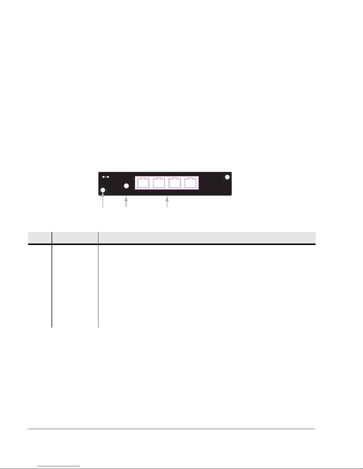
Chapter 7. Installing the INU and INUe
7-22 Stratex Networks
DAC ES
The DAC ES plug-in provides access for Ethernet traffic. Two radio-path 10/100
Base-T channels are individually configurable in capacity increments of 2 Mbps,
to ride side by side with TDM traffic, or the full capacity of the link can be
dedicated to Ethernet.
The two channels allow configuration of high priority and normal priority
queuing. The high priority queue supports selected traffic (assigned by port,
VLAN priority, or DiffServ/Type of Service tags). The DAC ES is field
replaceable and hot swappable.
Figure 7-12 shows the DAC ES front panel layout. Table 7-11 describes the
DAC ES front panel.
Figure 7-12. DAC ES Front Panel Layout
Table 7-11. DAC ES Front Panel Descriptions
DAC ES
Status
Port 1-4 10/100Base-T
14
12 3
No Item/Label Description
1 Card fastener Finger-grip screw-type fastener and card pull (2).
2 Status LED Status LED provides indications of:
Off INU power off
Green flashing Normal operation
Red/Green flashing Configuration not supported, software / hardware
incompatible or in diagnostic mode
1
Red Critical alarm
2
Page 97

Eclipse User Manual
260-668045-001 Rev 005 March 2004 7-23
AUX
The AUX card provides user-configurable auxiliary data channels, and alarm
input and output (I/O) options. Specifications and operation to be confirmed.
The AUX is field replaceable and hot-swappable, and can plug into any of the
four option slots in the IDC.
3 RJ-45 Port
Connector
Assembly
Four RJ-45 connectors labelled Ports 1 to 4 provide 10/100Base-T access to customer
networks. Internally, the interface implements an ethernet bridging/switching function.
Each RJ-45 port connector includes Activity and Connection LEDs:
Ethernet orange
LED
Orange flashing LED indicates Ethernet receive activity. Off indicates no receive
activity.
Ethernet green
LED
Green LED indicates connection of an Ethernet link. Off indicates no Ethernet link
connection.
1. Includes situations where the slot configuration does not support the card, where the card requires a later/different version of
software or where the card has been set for a tributary loopback.
2. Indicates a traffic-affecting hardware failure.
No Item/Label Description
Page 98
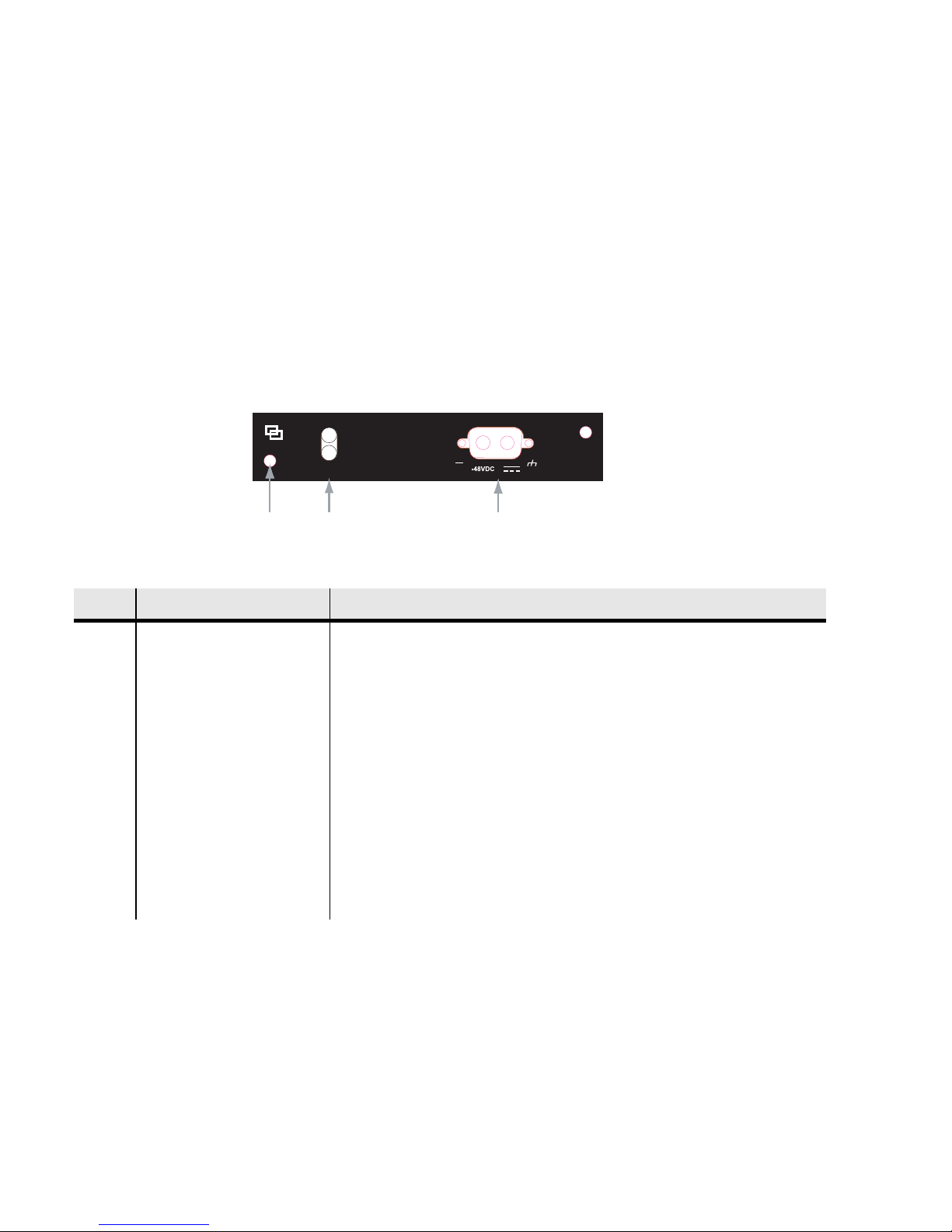
NPC
The NPC provides a protection option for the NCC with backup for TDM
backplane bus management, and power supply. Should either function fail on an
NCC, the NPC will maintain traffic without interruption. One NPC can be
installed per IDC or IDCe.
The NPC is field replaceable and hot-swappable, and plugs into slot 4 of the IDC,
or slot 10 of the IDCe.
Figure 7-13 shows the NPC front panel layout. Table 7-12 describes the NPC
front panel.
Figure 7-13. NPC Front Panel Layout
Table 7-12. NPC Front Panel Descriptions
Protect
Status
NPC
Protect
Status
NPC
12 3
-48VDC
No Item/Label Description
1 Card fastener Finger-grip screw-type fastener and card pull (2).
2 Protect LED Protect LED provides indications of:
Off Off-line
Green: On-line and in redundant mode
Status LED Status LED provides indications of:
Off INU power off
Green On-line and ready to protect
Red Critical alarm
3 -48 Vdc connector 2-pin power connector with screw fasteners
Page 99
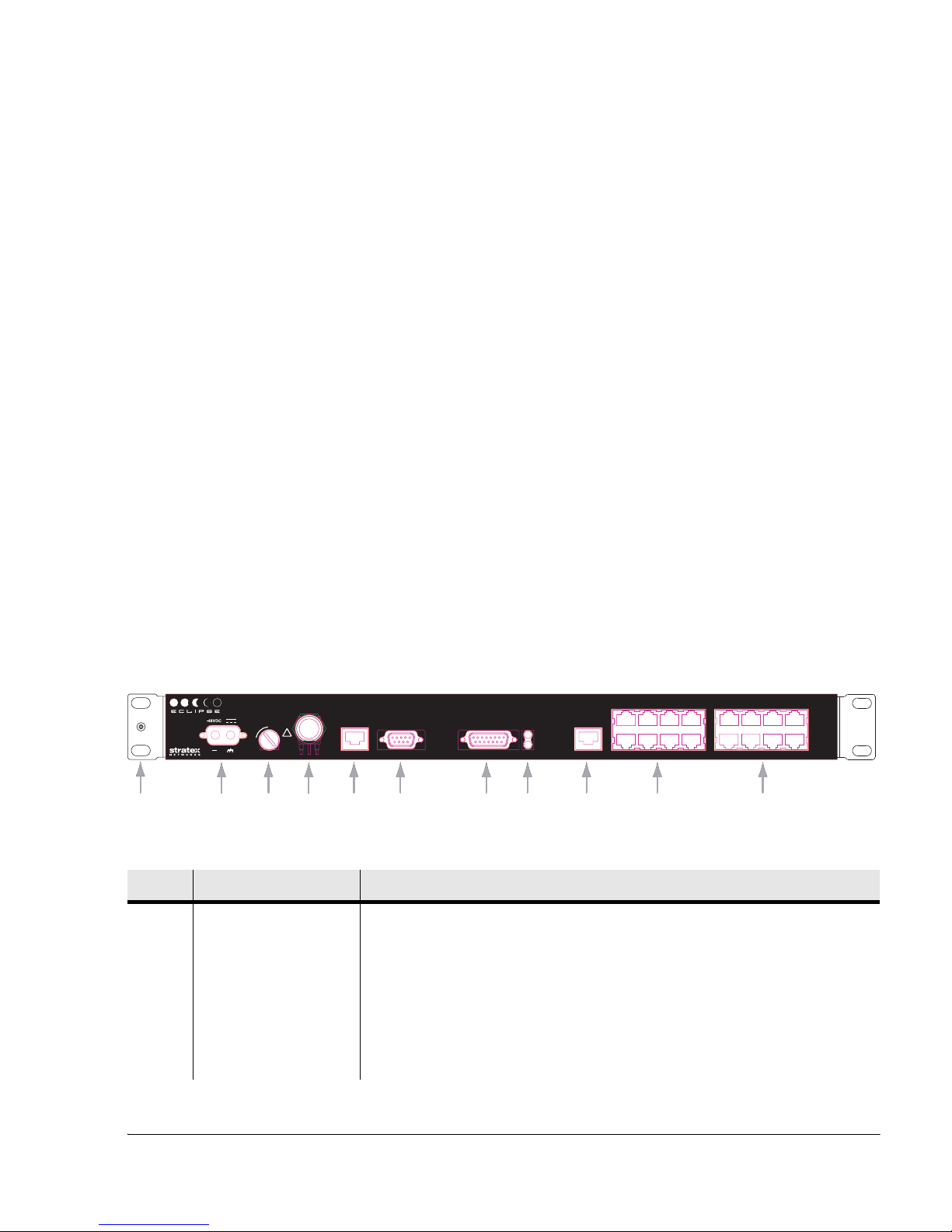
260-668045-001 Rev 005 March 2004 8-1
Chapter 8. Installing the IDU
References to IDU and Eclipse Terminal have the following meanings:
IDU, Indoor Unit. The IDU is a rack mounted unit, which when paired with the ODU 100
comprises the Eclipse Terminal.
Eclipse Terminal
refers to the IDU with ODU 100. Two versions are available;
an 8x with capacity settings for 4x or 8xE1, and a 16x with settings for 4x, 8x, or
16x. Modulation is QPSK only. Only a nonprotected option is provided.
The IDU is available in two variants:
• IDU 8x for data rates of 4 or 8xE1, and
• IDU 16x for 4, 8, or 16xE1
Both are for non-protected operation on bands 7 to 23 GHz. Modulation is
QPSK. Its companion ODU is the ODU 100.
Figure 8-1. IDU 16x Front Panel Layout
Table 8-1. IDU Front Panel Layout
No Item/Label Description
1 Rack Ear Rack attachment bracket for the IDU. One ear has a grounding stud, nut and
washer for IDU grounding. The ears can be fitted either-side. The standard ears
provide flush-with-rack-front mounting. Ear options are available to provide
set-back mounting.
2 -48VDC 2-pin power connector with screw fasteners.
3 Fuse 5A time-lag fuse and power on/off switch. ON is with the fuse head in the
vertical position; OFF is with the head rotated to the horizontal ‘0’ position.
1
2
3
456 78 9 10 11
IDU 16x
-48VDC
!
5A
0
I
Maint V.24 AUX Data
Alarm I/O
IDU Status
ODU Status
NMS 10/100Base-T
Tribs 1-8
2468
1357
Tribs 9-16
10 12 14 16
9111315
To ODUTo ODU
IDU 16x
!
5A
0
I
Maint V.24 AUX Data
Alarm I/O
IDU Status
ODU Status
NMS 10/100Base-T
Tribs 1-8
2468
1357
Tribs 9-16
10 12 14 16
9111315
Page 100

Chapter 8. Installing the IDU
8-2 Stratex Networks
4 To ODU Type N female connector for jumper cable connection to the surge suppressor.
5 Maint V.24 RJ-45 connector provides a V.24 serial interface option for Portal. A default IP
address means knowledge of the IDU IP address is not required at login.
6 Aux Data DB-9 connector provides one synchronous or asynchronous data service
channel. Selection of synchronous 64 kbps or asynchronous to 19.2 kbps is via
Portal.
7 Alarm I/O DB-15 connector provides access to two TTL alarm inputs and four form C
relay outputs. Connections are mapped in Portal.
8 ODU Status ODU Status LED provides indications of:
Off IDU power off
Green Normal operation
Red/Green flashing Configuration not supported or software/
hardware incompatible
Red Critical alarm
IDU Status IDU Status LED provides indications of:
Off IDU power off
Green Normal operation
Green/Red flashing Configuration not supported or software/
hardware incompatible
Red: Critical alarm (IDU traffic affecting). Fault
condition or diagnostics, such as
loopbacks, set.
9 NMS 10/100Base-T RJ-45 connector provides a port for Ethernet network management access.
ProVision and/or Portal login to this port requires entry of the IP address for the
IDU. Port may also be used to provide NMS connectivity to co-located Stratex
or third party radios.
Built-in orange flashing LED indicates Ethernet receive activity. Off indicates
no receive activity.
Built-in green LED indicates connection of an Ethernet link. Off indicates no
Ethernet link connection.
No Item/Label Description
 Loading...