

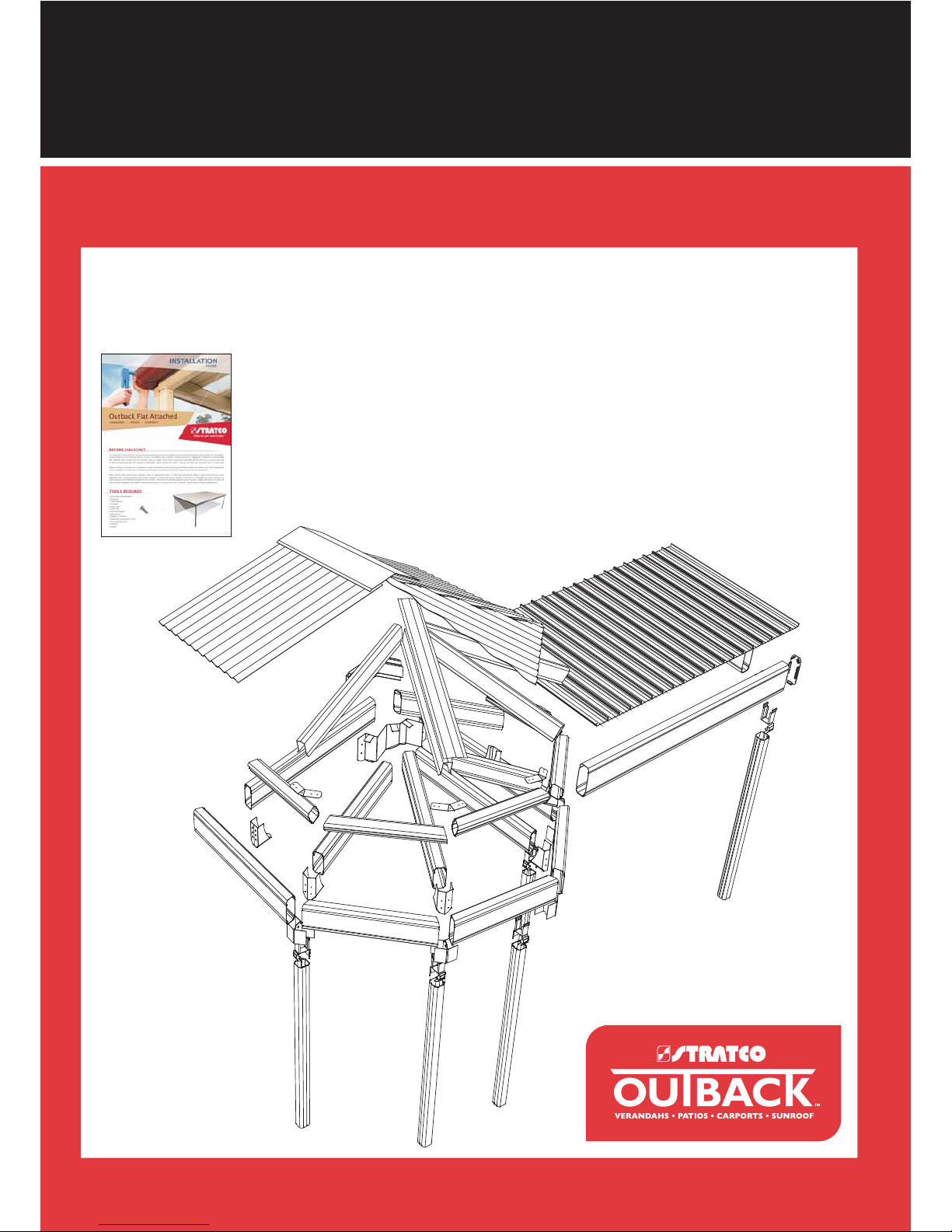
MULTISPAN GABLE
WITH GAZEBO END ATTACHED PATIO
STRATCO OUTBACK ASSEMBLY INSTRUCTIONS.
®
Your supplementary guide to building an
ATTACHED MULTISPAN GABLE VERANDAH or PATIO
WITH GAZEBO END
This set of instructions should be used in conjunction with the Stratco instruction brochure
‘ Your complete guide to building an Attached Outback
Verandah, Patio or Carport'.
Flat Verandahs Attached -
®
BEFORE YOU START
Carefully read these instructions, along with the Stratco Flat Verandahs Attached
Instructions. If you do not have all the necessary tools or information, contact Stratco
for advice. Before starting lay out all components and check them against the
delivery docket. The parts description identifies additional gable parts, and the
component layout diagram indicates their fastening position.

FINIAL
Provides decoration
at the apex of the
gable end frame.
PURLIN INTERSECTION
COVER
TEMPLATE
Fastened to hip
rafters to cover
purlins and
attach deck.
Used to mark the
purlin cover for
cutting around
purlins.
BEAM TO BEAM BRACKET
BEAM FILLER
Connects horizontal
beams.
Fills gap
between
intersecting
beams.
PARTS DESCRIPTION
1
BARGE CAP
The barge cap covers
the area where the
deck finishes at portal
frame.
SCREWS AND RIVETS
Fastener types vary depending
upon the connection, ensure
correct fixings are used.
14x95
12x20
10x16
RIVET
RIDGE KNUCKLE
Slots inside the gable rafters to
form connection at the ridge.
RIDGE CAP
This flashing covers the
roof sheets at the gable
ridge and the Gazebo End
hips.
22 or 30 END
RAFTER
BRACKET
Connects rafters to
header beam on an
infill gable.
ºº
END STRUT
The gable infill is
supported by the
end strut, which
consists of a section
of post.
22 or 30 END
STRUT PLATE
Secures the end
strut at the ridge.
ºº
PURLINS
Purlins provide support for
cladding.
RAFTERS
Gable Rafters
consist of pre-cut
120 Outback
beam.
®
SOAKER FLASHING
The soaker flashing
water proofs the rear
of the gable and
conceals the existing
house gutter.
PERIMETER
BRACKET
This bracket
fastens the
rafters to the
gazebo fascia
beam.
APEX BRACKET
This bracket fastens the hip
rafters to the apex of the gable
frame.
ANGLED INLINE
CONNECTORS
135°Angled Purlin
Connector.
67.5° Angled Inline
Connector.
BOLTS
Fastener types vary depending
upon the connection, ensure
correct fixings are used.
M10 HEX
HEAD BOLT
M12 HEX
HEAD BOLT
CUPHEAD
BOLT
RAFTER TO
VALLEY
BRACKET
This bracket
fastens the
rafter to the
valley beam.
SPACERS
Are used to prevent the
150 attachment beam
from crushing.
HEADER BEAM BRACKET
Connects end strut to header
beam on an infill gable.
HEADER FLASHINGS
Run along header beam to
neatly finish the base of
infill panels.
PANEL STRIPS
Decorative strips fixed to
infill panels.
INFILL PANEL
Cut to suit gable end
frames.
POST BRACKET
POST CAP
Connects post
to beam.
Fills gap between
post and beam.
7
8
9
10
6
5
4
3
2
1
Ridge Cap
Outback Deck
Purlin
Ridge Knuckle
Rafter
Valley Beam
Beam to Beam Bracket
®
®
Polycarbonate Sheet,
Outback Deck or CGI
Notched Beam Filler
15
14
13
12
11
Rafter to Valley Bracket
Post Bracket
Post
Front Fascia Beam
End Fascia Beam
Gutter
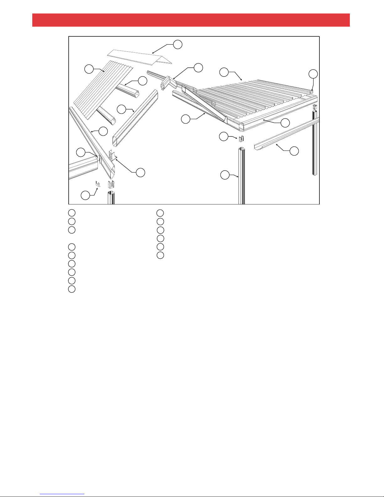
COMPONENT LAYOUT
1
4
7
10
3
2
6
8
12
11
5
13
7
15
14
9
1
GABLE FRAME
(GAZEBO END)
2

COMPONENT LAYOUT
7
8
9
10
6
5
4
3
2
1
Ridge Cap
Purlin
Purlin Intersection Cover
Ridge Knuckle
Hip Rafter
Gazebo Fascia Beam
135
Gazebo Apex Bracket
Polycarbonate Sheet,
Outback Deck or CGI
®
° Angled Purlin Connector
14
13
12
11
Rafter to Valley Bracket
Post Bracket
Post
67.5 Angled Inline Beam Connector
Perimeter Bracket
Hip Support Flashing
°
2
3
1
2
3
4
5
6
7
8
9
10
11
12
13
14
GAZEBO END
15
15
ADDITIONAL MATERIALS
These materials are needed to complete the job, but are not
included in the basic kit price (they must be purchased as
extra items, and their quantities specified):
Rafter strengthening brackets and channels to suit 150
attachment beam for attaching gable to house.
M12 bolts and nuts for fixing strengthening brackets to the
rafter.
M12 bolts and nuts for fixing 150 attachment beam to
strengthening brackets.
Fascia Brackets for attaching gable on end to house.
M10 coach bolts and nuts for fixing fascia brackets to the
house rafter.
M8 masonary anchors for fixing Wall Brackets to masonary.
12x25 type 17 hex head screws for fixing Suspension
Brackets to timber.
10x16 hex head screws for fixing Suspension Brackets to
steel fascia.
Cover flashings (measurements required).
Box gutter (measurements required).
These items are available at request:
Infill Panels
Panel Strips
Finial
Soaker Flashing in lieu of Header Flashing
Purlin Intersection Cap
OPTIONAL EXTRAS
1.0 INTRODUCTION
2.0 ATTACHING TO AN EXISTING
STRUCTURE
2.1 ATTACHING ON SIDE TO HOUSE
Please read these assembly instructions thoroughly before
commencing the construction. Double check all
dimensions, levels and bolting locations before cutting,
screwing or bolting structural members. It is recommended
that the persons erecting the structure have had some
previous building experience because some modifications
to the existing house structure are required.
The builder or council is to ensure the existing
house/structure is of a suitable structural integrity and
complies with all the relevant Australian Building codes and
standards. For more information regarding the suitability of
the house structure to accommodate the Stratco Attached
Multispan Gable, consult a structural engineer or a building
authority. It is the builders responsibility to ensure that the
existing house roof structure is strengthened correctly.
Refer to section 2.1 if attaching Multispan Gable on it’s side
to a house, section 2.2 if attaching on it’s end to a house or
refer to both sections if attaching the gable on it’s side and
end.
A Stratco Multispan attached on it’s side to a house is
attached to the existing eaves overhang at the fascia.
The first objective in the construction is to fix a structural
side beam along the fascia or wall, to which the Gable Unit
is attached.
Most existing houses have not been designed for the
attachment of portal framed gables to their side, therefore
additional strengthening of the house rafters must be
performed.
In order to strengthen the existing house rafters, the roof
tiles or roof sheets need to be lifted to expose the roof
frame. Steel rafter brackets and channels are then bolted
along the house rafters. Refer to section 2.1.1.
A 150 mm Outba beam is bolted to the strengthening
brackets at the fascia. Once the 150 attachment beam is
secured to the house, the Gable Unit can be erected and
fastened to the beam.
The first step is to determine the number of rafters which
need to be strengthened and their location relative to the
unit. You will have to lift some roof tiles or roof sheets to
discover the rafter positions and spacings. The number of
rafters which need to be strengthened is determined by the
builder.
: It is the builders responsibility to ensure the existing
rafters and fascia are adequately reinforced and
strengthened to accommodate any additional attached
structure. The reinforcing method must be approved by the
appropriate council or engineer.
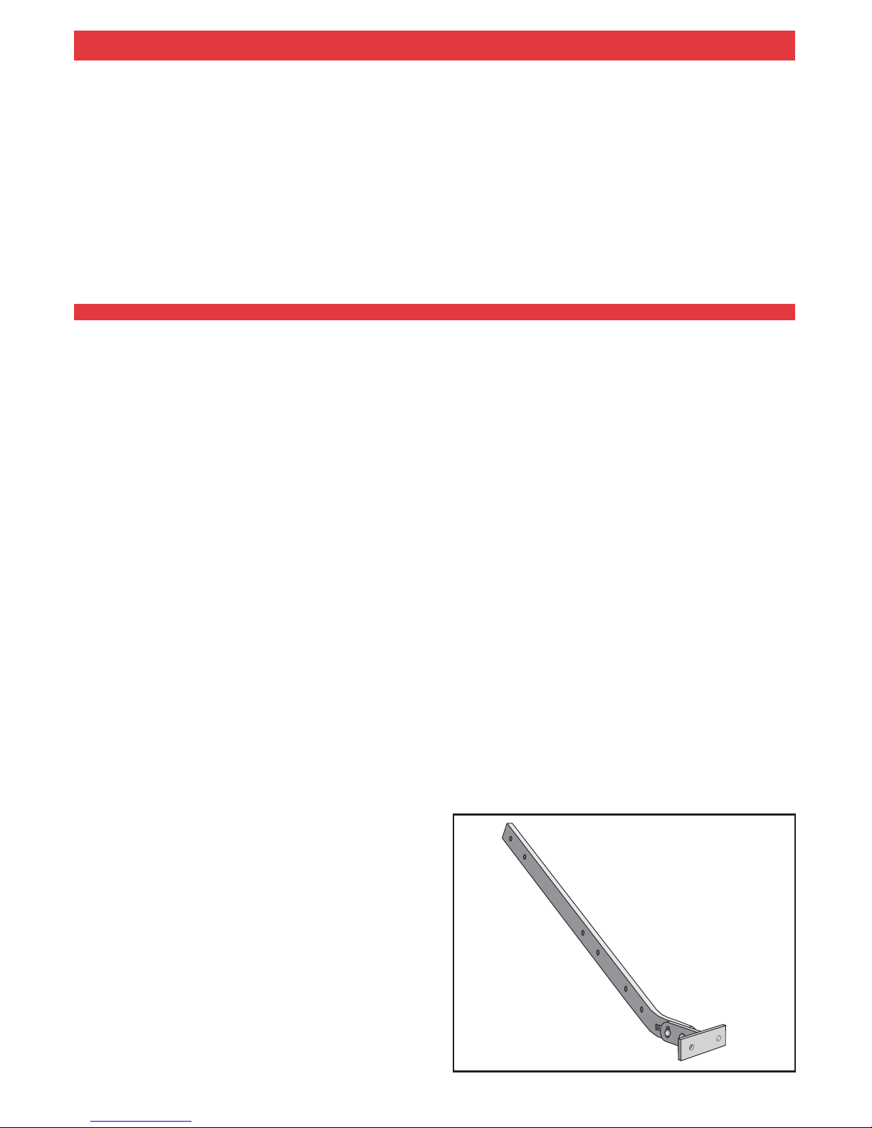
Use an adjustable rafter strengthening bracket and one
channel for eaves overhangs up to 450 mm. Use an
adjustable rafter strengthening bracket and two channels
for eaves overhangs over 450 mm and up to and including
600 mm, as shown in figure 4.
The adjustable rafter strengthening bracket is shown in
figure 3. Please note that this bracket may not be suitable
for applications where the front face of the house gutter is
higher than 120 mm. In these cases please contact Stratco
for alternative solutions.
ck
®
Note
2.1.1 RAFTER STRENGTHENING
4
ADJUSTABLE RAFTER STRENGTHENING
BRACKET
3
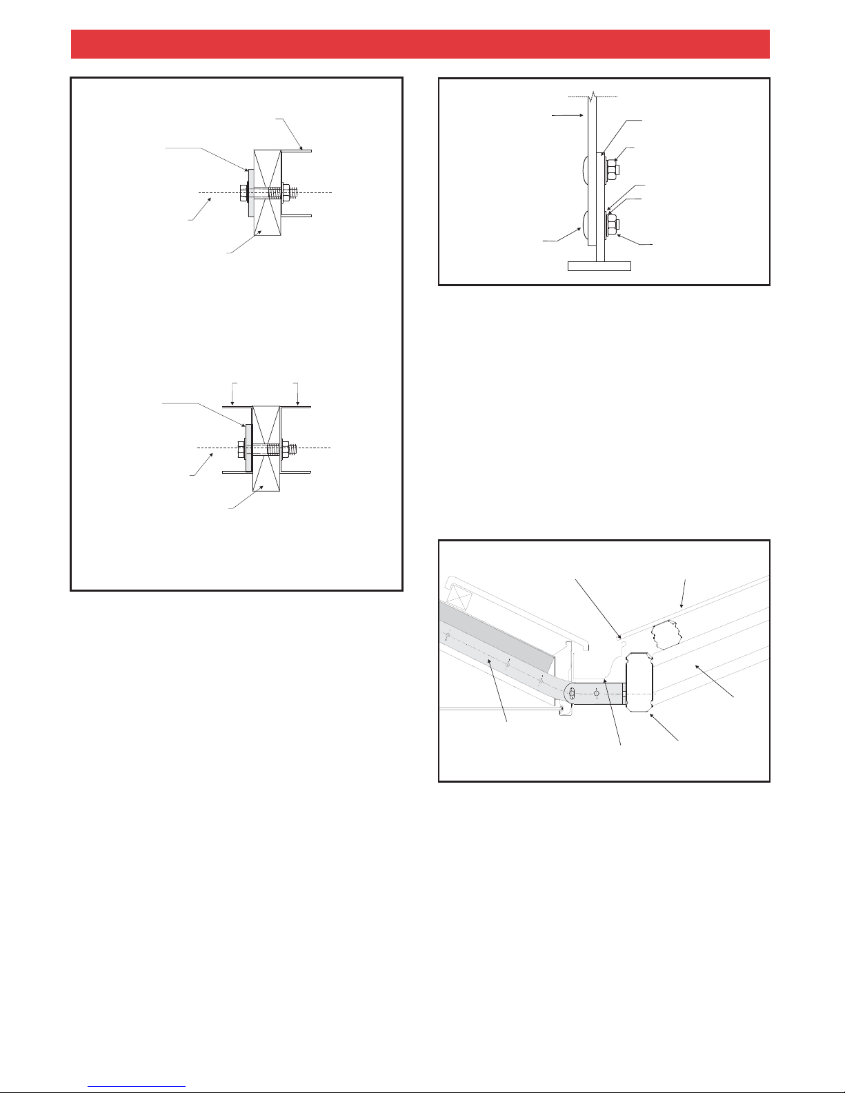
4
450mm EAVES OVERHANG
RAFTER
STRENGTHENING
BRACKET
M12 BOLT
TIMBER RAFTER
60x44x2.0 G450 GALVANISED
CHANNEL
600mm EAVES OVERHANG
RAFTER
STRENGTHENING
BRACKET
M12 BOLT
TIMBER RAFTER
60x44x2.0 G450 GALVANISED
CHANNEL
RAFTER
6
ENOUGH CLEARANCE FOR
ROOF SHEETS TO RUN INTO
THE HOUSE GUTTER
FIX BRACKET AS CLOSE
AS POSSIBLE TO THE BASE
OF THE GUTTER
RAFTER
STRENGTHENING
BRACKET
CGI, POLYCARBONATE
OR
OUTBACK ROOF SHEET
®
150 ATTACHMENT
BEAM
Fixing the 150 Attachment Beam in Place
After fixing all the brackets and channels, the 150
attachment beam is fixed in place.
Prop up the 150 attachment beam in position with the
double flange on top, the beam will need to be located at a
height on the bracket which allows clearance between the
gable roof sheets and the gutter. Fix to the end plates of the
rafter bracket using two M12 bolts, with the bolt head on the
150 attachment beam side. Insert spacers to prevent the
beam from crushing, and bolt in position, using nuts and
washers.
Do not over tighten bolts as this can lead to a visible
indentation due to the high gloss nature of the material.
Refer to Figure 8 for fixing spacers.
Note:
5
Fixing Rafter Strengthening Brackets and
Channels
The adjustable rafter strengthening bracket allows for an
adjustment of pitch in the range of 15 to 30 degrees. The
distance the bracket extends past the fascia is also
adjustable to allow for standard gutters or box gutters with a
width of up to 200mm.
In conjunction with rafter strengthening brackets, channels
are fixed to the side of the house rafter (Figure 4). The
bottom end of the channel will be located at the base of the
house rafter. Holes should be marked and pre-drilled in the
channels to suit the location of existing holes in the bracket.
The channel will extend beyond the bracket so additional
holes are to be drilled in the channel at approximately
500mm centres.
Initially the bracket T piece shall be fixed to the bracket arm
with two M12 cup head bolts (hand tighten only), a spring
washer is to be located between the standard M12 washer
and nut (Figure 5). Mark the position of the bracket on the
fascia and notch a rectangular hole in the fascia allowing
the bracket to be fed through thefrontof the fascia. The hole
may need to be enlarged slightly if the M12 cup head bolts
interfere with the fascia.
5
BRACKET ARM
T PIECE
TIGHTEN TO 35Nm
TORQUE
M12 WASHER
M12 SPRING WASHER
M12 NUT
M12x40 CUP HEAD
BOLT
Insert the bracket through the fascia and fix with the
channel(s) to the house rafter using M12 hex head bolts
through the existing holes in the bracket and further up the
channel(s) (Figure 7). Adjust the T piece so it is horizontal
and has the appropriate extension past the fascia to allow
for fixing of the attachment beam. T piece connection bolts
are to be tightened to a minimum 35Nm torque.
Fix the bracket as close to the baseofthe gutter as possible
(recommended distance 10mm from lowest end of gutter),
as shown in figure 6.
The 150 attachment beam is to be fixed to the end plate to
ensure the carport roof sheets drain into the existing house
gutter (Figure 6).

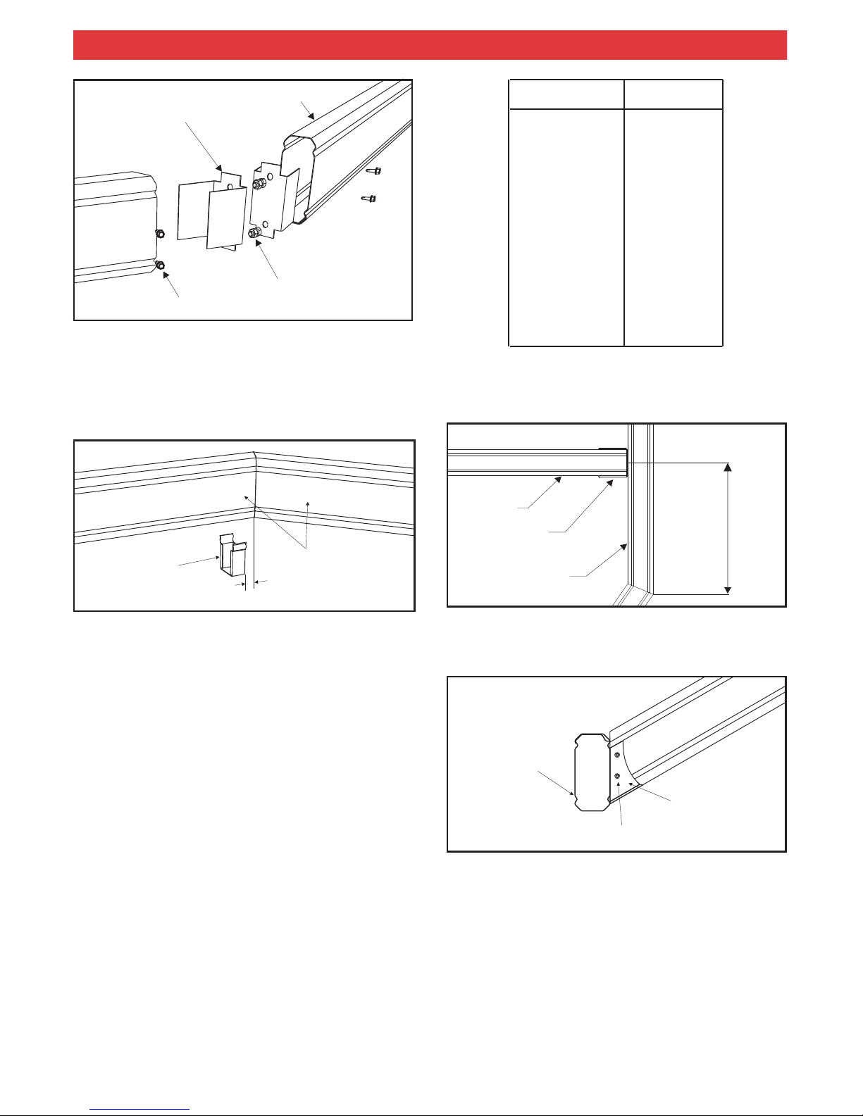
The 150 attachment beam becomes the base for the attachment of the Multispan gable unit. Figure 7 shows a unit attached at
the side.
7
CHANNEL EXTENSION
MULTISPAN GABLE ATTACHED AT THE SIDE
WEB OVERHANG
STUD WALL
TIMBER RAFTER
150 ATTACHMENT BEAM FIXED TO
RAFTER BRACKET WITH TWO
M12 BOLTS
GUTTER
150 ATTACHMENT BEAM
EAVES OVERHANG
BRICK WORK
RAFTER STRENGTHENING BRACKET
ATTACHED TO RAFTER WITH
6 (M12 HEX HEAD BOLTS)
RAFTER
EAVES PURLIN
FIXED TO
RAFTER USING
14 x 95 SCREWS
To insert spacers drill 11 mm holes through the 150
attachment beam. Then drill 16 mm holes on the outside
face only, ie, this time do not drill all the way through. This
will allow the spacer to slide in from the outside and stop at
the other side as shown in figure 8.
6
8
150 ATTACHMENT BEAM
SPACER
NUT
RAFTER
STRENGTHENING
BRACKET
M12 BOLT
DOUBLE FLANGE
ENLARGED HOLE
(16 MM THIS SIDE ONLY)
11 MM HOLE
WASHER
You would have ordered and received your custom made
flashings to cover the exposed brackets and holes through
fascia. Rivet flashings in place, figure 9 suggests a
simplified flashing. You may however use your imagination
and design a flashing that suits your individual taste.
Note: It is the builders responsibility to ensure the existing
rafters and fascia are adequately reinforced and
strengthened to accommodate any additional attached
structure. The reinforcing method must be approved by the
appropriate council or engineer.
If fixing a Multispan Gable on its end to a wall, two
alternatives are available. Purlins are fixed directly to the
wall using 68mm wall brackets andvalley beams using 150
beam to wall brackets. This option will not require a rear
gable frame and back channel is fixed to the wall to
accommodate sheets running along the wall. The other
alternative requires valley beams be fixed to the wall and a
rear gable frame installed for fixing purlins. The rear gable
frame will need to be slightly offset from the wall to allow the
appropriate bracket fixing.
If fixing a Multispan Gable on its end with suspension
brackets to a fascia (Figure 10), typically a soaker flashing
is used. In this case the gable rafter at the rear of the unit
2.2 ATTACHING ON END TO HOUSE
450
600
1800
1900
300
400
Eaves
Overhang
(mm)
Channel Extension
Beyond Birds Mouth
(mm)
Web Overhang
(mm)
Recommended Channel Extension
CHANNEL
WASHER
9
COVER FLASHING
(OPTIONAL)
RIVET
RIVET
STRENGTHENING
BRACKET
FASCIA
150 ATTACHMENT
BEAM
HOUSE
GUTTER

Measure the distance between rafter ends, O, to check
valley beam spacing (Figure 13).
13
GABLE OPENING (O)
12
2 (12 X 20 HEX HEAD SELF
DRILLING SCREWS) EACH
SIDE OF BOTH RAFTERS
2 (12 X 20 HEX HEAD SELF
DRILLING SCREWS) THROUGH
TOP OF BOTH RAFTERS
11
OPEN GABLE RAFTER
INFILL GABLE RAFTER
7
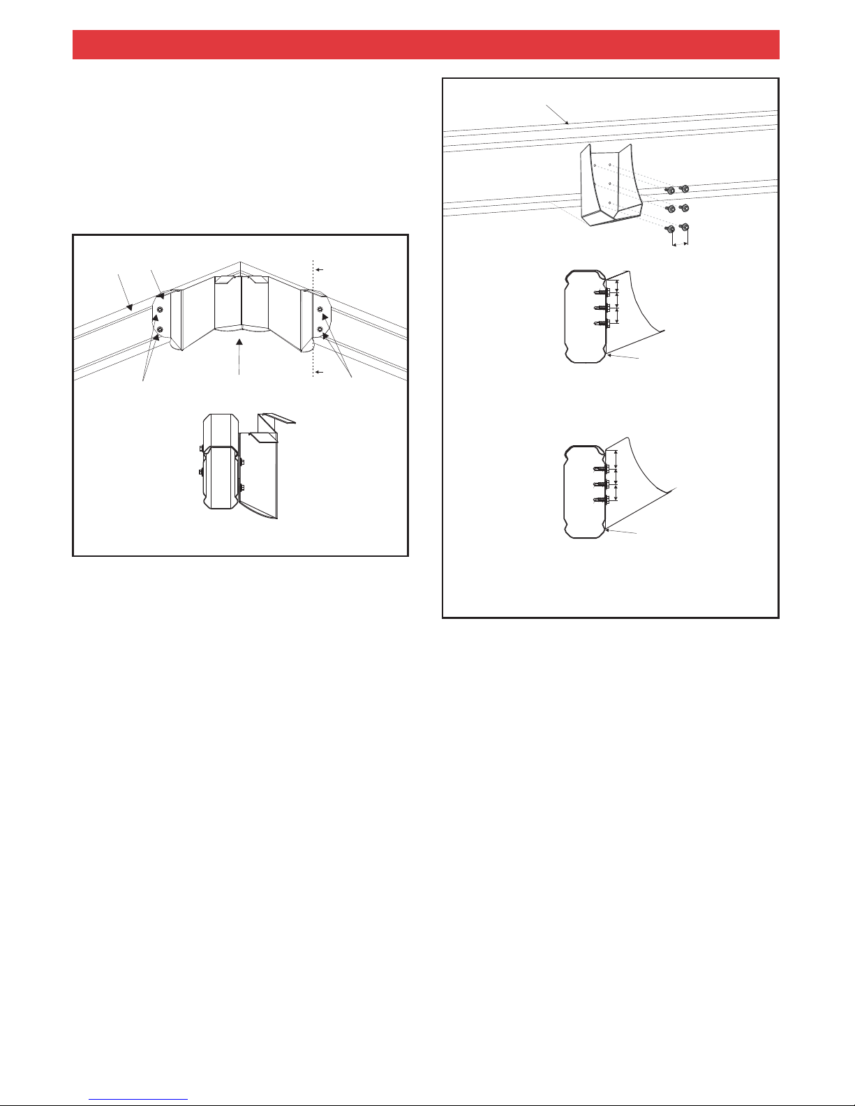
Insert ridge knuckle into the pre-cut rafters and screw
together using two 12x20 hex head self drilling screws both
sides of each rafter and two 12x20 hex head self drilling
screws through the top (double flange side) of each rafter.
Pilot holes indicate screw locations as shown in figure 12.
Make sure that the two ends are flush at the connection,
leaving no gaps.
10
120 GABLE RAFTER
INFILL PANEL
GUTTER
SOFFIT LINING
SUSPENSION
BRACKET
VALLEY BEAM
BACK CHANNEL
STEEL FASCIA BRACKET
(ATTACHED TO RAFTER
AND BACK CHANNEL)
3.0 GABLE FRAME ASSEMBLY
IMPORTANT:
Note:
Ensure that the double flange portion is at
the top when installing all beams and rafters.
The rafters are supplied pre-cut and drilled at the
ridge as shown in figure 11.
is to be 153mm from the house fascia in order to
accommodate a standard soaker flashing (refer Figures 24
and 25).
If your house gutter is wider than 150mm a custom
made soaker flashing will need to be ordered and the rafter
set back adjusted to suit.
If fixing a Multispan Gable on its end to an attachment
beam, elevated to the existing house gutter height, the
attachment beam is to be as close as possible (within 5mm)
to the outside face of the gutter (Figure 26). The 150
attachment beam is fixed to rafter strengthening brackets
as detailed in section 2.1.1.
It is the builders responsibility to ensure the existing
rafters and fascia are adequately reinforced and
strengthened to accommodate any additional attached
structure. The reinforcing method must be approved by the
appropriate council or engineer.
Note:
Note:
2.2.1 FASCIASTRENGTHENING
Steel fascia brackets are generally fastened at 1200mm
centres to fascia and rafters (Figure 10). It is the builders
responsibility to determine the adequacy of the fascia and
rafters and the frequency of brackets for each individual
situation.
SOAKER FLASHING
8
A Gazebo Apex Flashing is secured with rivets behind the
apex bracket and will cover gaps created by purlin
intersection covers (Section 9.3).
For side attached units fix the rafter to valley bracket to the
valley beam (150 attachment beam will be considered a
valley beam) at the correct rafter positions (refer Section 6)
using six 12x20 hex head screws per bracket through the
pre-drilled holes (Figure 15). Pleasenote the bottom face of
the bracket lines up with the bottom edge of the lower
groove in the valley beam for 150 beams (Figure 15). Check
positions before drilling.
If any intermediate columns are required, measure the
valley beam marking where they meet. Fasten post
brackets as explained in ‘Outback Flat Attached
Verandahs, Patios & Carports’ under “FRONT FASCIA
BEAM”.
Support the second valley beam at the spacing determined
in part 3.0 on adjustable construction props.
4.0 VALLEYBEAMASSEMBLY
4.1 SIDE ATTACHED
3.1 APEX BRACKET
The Gazebo Apex bracket is to be fixed to the front face of
the front gable frame at the apex. The bracket is to be
located so the bottom edge of the apex bracket is in-line
with the top edge of the bottom chamfer of the gable frame
rafters. The apex bracket is to be located centrally at the
apex and fixed through the pre-drilled holes using 12x20
hex head screws (Figure 14).
14
APEX BRACKET
RAFTER
12x20 HEX HEAD
SCREWS
12x20 HEX HEAD
SCREWS
SIDE FIXING
TAB
A
A
SECTION A-A
4.2 END ATTACHED
For units attached on the end to a wall, wall brackets are
positioned at either side of the gable opening at the spacing
determined in part 3.0. The first bracket is fastened to the
wall with two M8x65mm masonry anchors.The curved legs
of the bracket are located at the top and the highest point of
the wall bracket will be 15mm below the top of the beam
(Figure 16).
Pivot the first valley beam (double flange on top) up into the
wall bracket so the curved legs locate against the top flute of
the beam. The valley beam is fastened to the wall bracket
with 10x16 hex head screws in the pre-drilled holes while
the opposite end is supported on adjustable construction
props.
40
150 VALLEY
BEAM
150 VALLEY BEAM WITH 30°
RAFTER TO VALLEY BRACKET
30
25
150 VALLEY BEAM WITH 22°
RAFTER TO VALLEY BRACKET
20
25
BRACKET POSITION INLINE WITH
THE BOTTOM EDGE OF THE
LOWER GROOVE
15
BRACKET POSITION INLINE WITH
THE BOTTOM EDGE OF THE
LOWER GROOVE
25
25

9
For units attached on the end to a fascia, suspension
brackets are positioned ateither side of the gable opening
at the spacing determined in section 3.0 (Figure 13). The
top tab of the suspension bracket must be located
between the fascia and back channel. A minimum of two
10x16 hex head screws are fixed through back channel,
suspension bracket and steel fascia while two 12x25 type
17 screws are used to fix through back channel,
suspension bracket and timber (Figure 17).
If back channel is not present, (ie, no adjacent flat
roof) locate washer plate behind steel fascia at
suspension bracket. Fix through bracket, fascia and plate.
The first valley beam is fastened into the suspension
bracket with 10x16 hex head screws through the dimples
while the opposite end is supported on adjustable
construction props.
Note:
16
WALL
BRACKET
TWO 10x16
HEX HEAD SELF
DRILLING SCREWS
EITHER SIDE
TWO M8x65 MASONARY ANCHORS
or
TWO 6mm DIAMETER SCREWBOLTS
WITH A MINIMUM EMBEDMENT OF 45mm
MINIMUM EDGE DISTANCE OF BOLTS &
SCREWS IS (10 x dia)
15mm
17
OUTBACK
DECK
®
1.0mm STEPPED
BACK CHANNEL
VALLEY EAMB
SUSPENSION
BRACKET
10x16 HEX HEAD SCREWS TO STEEL
12x25 TYPE 17 SCREWS TO TIMBER
For units attached on the end to an attachment beam
(Figure 26), beam to beam brackets are positioned at either
side of the gable opening at the spacing determined in
section 3.0 (Figure 13).
18
TWO 10x16 HEX
HEAD SELF DRILLING
SCREWS EITHER SIDE
BEAM TO
BEAM BRACKET
BEAM FILLER
ATTACHMENT
(HEADER) BEAM
TWO 10x16 HEX HEAD
SELF DRILLING SCREWS
If any intermediate columns are required measure the
valley beam marking where they meet. Fasten post
brackets as explained in the installation guide ‘Outback Flat
Attached Verandahs, Patios & Carports’ under “FRONT
FASCIABEAM”. This can be done before valley beams are
fixed in place.
Support the second valley beam on adjustable construction
props but do not fix to the wall, fascia or attachment beam
until the front gable frame has been attached.
Fix the rafter to valley brackets to the valley beam at the
correct rafter positions (refer Section 6). Fixing details as
indicated in section 4.1.
Attach the in-line connector brackets back to back using
M10 bolts and nuts in the holes provided (Figure 19).
Ensure the constructed bracket makes the required
internal angle of 135 degrees.
Slide the in-line connector into the valley beam and fix
using two 12x20 hex head screws to the outside face of the
beam only. Fix one of the three Gazebo Fascia Beams to
the protruding half of the in-line connector using two 12x20
hex head screws to the outside face of the beam ensuring
both beams are flush with one another. Support the first
gazebo fascia beam on an adjustable construction prop.
Repeat the above process on the centre gazebo fascia
beam. Fix the remaining in-line connectors to the free ends
of the fascia and valley beams. The final gazebo fascia
beam is now be fixed in place.
5.0 GAZEBO FASCIA BEAMS .
Fix beam to beam brackets to the attachment beam
(header beam) with two 10x16 hex head screws so they
clamp the beam filler to the beam (Figure 18).
The first valley beam is fastened over the beam to beam
bracket with two 10x16 hex head screws either side while
the opposite end is supported on adjustable construction
props.
19
INLINE CONNECTOR
12x20 HEX HEAD SCREW
M10 BOLT
GAZEBO FASCIA BEAMS
20
POST BRACKET
GAZEBO FASCIA
BEAMS
With all the gazebo fascia beams secured, post brackets
are to be fastened approximately 60mm from the fascia
beam joins (Figure 20), allowing for perimeter brackets and
post caps. Refer to, ‘Your complete guide to building an
attached verandah, patio or carport’ under “FRONT
FASCIABEAM” forpost bracket fixing details.
6.0 GABLE FRAME CONNECTION
Note: Be aware that gable frames are always 120 beams
and valley beams are always 150 beams for Multispan units
with a gazebo end.
The front gable frame will need to be set back from the front
of the valley beams to accommodate the gazebo end. Refer
to Figure 21 and Table1 for set back distance.
The rafter to valley brackets will have been attached to the
valley beams using six 12x20 hex head screws (Figure 15,
Section 4) at the location determined from Table 1 (Figure
21).
6.1 GABLE FRAMES
(Figure 1)
150
VALLEY BEAM
120 RAFTER
RAFTER TO VALLEY
BRACKET
22
Fix the gable rafters into the rafter to valley brackets with
two 12x 20 hex head screws either side (Figure 22).
VALLEY BEAM
21
RAFTER
A (SET BACK)
RAFTER TO VALLEY
BRACKET
Table 1
Interpolation may be used to determine values
between those shown.
All lengths in millimetres (mm).
OPENING, O
A(Set Back)
1200
1500
1800
2100
2400
2700
3000
3300
3600
3900
4200
4500
4800
5100
5400
5700
6000
6300
6600
1022
1084
1147
1209
1333
1395
277
339
401
463
525
587
649
712
774
836
898
960
1271
TWO 12x20 HEX HEAD
SCREWS EITHER SIDE
If attached on the end, attach the second valley beam into
the wall or suspension bracket.
If the unit includes rear infill a rear header beam is
required and must be installed before fixing the second
valley beam in position, refer section 6.2.
Intermediate frames should be spaced evenly and fixed into
rafter to valley brackets as previously described.
A rear gable frame without a header beam is fixed as per an
intermediate frame.
Note:
10
60mm

6.2. REAR INFILL
A rear header beam will be required if the unit includes infill
to the rear gable frame. For units attached at the rear with
suspension brackets, the rear header is fixed between
valley beams using beam to beam brackets. If fixed at the
rear to an attachment beam (Figure 26), the attachment
beam becomes the header (valley beams are fixed to the
header beam) and if attached on the side the rear header is
fixed to the attachment beam with beam to beam brackets.
Attach end rafter brackets to the rear header beam at
spacing, O, as determined in section 3 using six 10x16
hex head self drilling screws (Figure 23).
Fasten the rafters that form the end gable frame over the
end rafter brackets with a minimum of two 10x16 hex
head screws either side (Figure 23).
Refer section 14 for details of fixing infill panels to gable
frames.
6.2.1 SOAKER FLASHING
In the case of a rear infill panel, a soaker flashing is used to
conceal the existing house gutter, waterproof the rear end
of the gable and neatly finish the base of the infill panel
(Figure 24).
The rear gable frame and header beam are positioned 153
mm from the house fascia in order to accommodate the
standard soaker flashing which is optional with the
Outback unit (Figure 25). The frame is fixed on the rear
header over end rafter brackets (Figure 23).
Fix the standard soaker flashing into position on top of the
back channel and underneath the gutter. Infill panels must
be fixed with split tail soft pull rivets at 500mm centres a
minimum of 20 mm above the pan of the soaker flashing.
This will reduce the possibility of moisture being absorbed
into the sheet.
Refer section 14 for details of fixing infill panels to gable
frames.
®
25
120 GABLE RAFTER
INFILL PANNEL
GUTTER
SOFFIT LINING
SUSPENSION
BRACKET
20mm GAP
VALLEY BEAM
BACK CHANNEL
153MM
SPLIT TAIL SOFT
PULL RIVETS
24
SOAKER
FLASHING
SOAKER FLASHING
Note:
1. If your house gutter is wider than 150 mm a custom made
soaker flashing will need to be ordered to the required
dimensions. The rafter setback will need to be adjusted to
suit.
2. Do not form stop ends at either end of the soaker flashing.
3. Soaker flashing is not to come in contact with the base of
the house gutter.
6.2.2 HEADER FLASHING
When a gable is fixed at the rear to an attachment beam,
elevated to the existing house gutter height, typically a
header flashing is used in conjunction with the rear infill. In
this case, the rear attachment beam is considered a
header,and along with the reargable frame is fixed as close
as possible (within 5mm) to the existing gutter in order to
accommodate the header flashing.The gable frameis fixed
on the rear header over end rafter brackets (Figure 23).
Fix the header flashing into position over the existing gutter
lip with rivets. Infill panels are located behind the header
flashing and fixed with split tail soft pull rivets at 500mm
centres (Figure 26).
Refer section 14 for details of fixing infill panels to gable
frames.
11
23
END RAFTER
BRACKET
HEADER BEAM
RAFTER
ATTACH RAFTER TO
BRACKET USING A MINIMUM
OF TWO 10x16 HEX HEAD
SELF DRILLING SCREWS
EACH SIDE
ATTACH END RAFTER
BRACKET USING A MINIMUM
OF SIX 10x16 HEX HEAD
SELF DRILLING SCREWS

26
STRENGTHENING
BRACKET
FASCIA
150 ATTACHMENT
BEAM
HOUSE
GUTTER
INFILL PANEL
HEADER FLASHING
SPLIT TAIL
SOFT PULL RIVET
27
PERIMETER BRACKET
12x20 HEX HEAD
SCREWS
GAZEBO FASCIA
BEAMS
7.0 PERIMETER BRACKETS
Perimeter brackets are to be located at the internal join of
the gazebo fascia beams so the bottom face of the bracket
is in-line with the bottom of the lower groove in the beams
(Figure 27). Brackets are to be fastened to the gazebo
fascia beams using four 12x20 hex head screws through
the pre-drilled holes.
12
8.0 GAZEBO HIP RAFTERS
Having all the Perimeter Brackets in place will allow rafters
to be located. The two shorter rafters are to be positioned
closest to the end gable frame on either side. It is important
that rafters are firstly fixed at the apex, position rafters over
the apex bracket tabs so the cut face of the rafter is flush
with the face of the bracket.
Two 12x20 hex head screws are used to fix the rafter to the
tab with the first screw being located 20mm from the front
face of the bracket and the second 20mm from the first
screw (Figure 28). This process is repeated for the two
internal gazebo hip rafters.
HIP RAFTERS
12x20 HEX HEAD SCREWS
GAZEBO APEX
BRACKET
INTERNAL HIP
RAFTER
GAZEBO APEX
BRACKET
20
20
28
With all gazebo rafters fixed at the apex they can be
fastened to the perimeter brackets. Fix rafters through the
base of the perimeter brackets using two 12x20 hex head
screws at a minimum spacing of 30mm. As a small
tolerance is allowed for at this bracket it is important that the
screws are located at least 20mm from the bracket edge
and the bottom edge of the rafter (Figure 29).

9.0 PURLINS
9.1 CUTTING PURLINS
The location of all the purlins must be known before any
purlins are to be cut.The top purlin is positioned amaximum
of 100mm from the gable ridge (Figure 30) and ends at the
front edge of the gable frame on either side. The end of this
purlin is cut straight to be left flush with the top of the rafter
chamfer (Figure 31).
The lowest purlin shall be amaximum 50mm from the valley
beam (Figure 30) and any intermediate purlins are spaced
evenly on rafters, ensuring maximum recommended deck
end spans are not exceeded. Both the lowest purlin and
intermediate purlin/s will follow the shape of the gazebo end
and therefore purlins will need to bemitred at 67.5 to length
to suit this shape. The highest edge of the gazebo end
purlins will end at the centre of the top face of gazebo hip
rafters. Refer to Figure 31 for further details.
It is recommended the three lowest purlins around
the front of the gable end are set as low as possible on the
hip rafters to eliminate any gap between purlins and gazebo
fascia beams. It is not critical that the level of the lowest
purlins exactly match the purlins adjacent to the valley
beams.
°
Note:
HIP
RAFTER
PERIMETER BEAM
BRACKET
GAZEBO FASCIA
BEAM
12x20 HEX HEAD
SCREWS
>20
>30
>20
29
31
CENTRE LINE
HIP RAFTER
PURLINS
67.5° MITRE
STRAIGHT
CUT
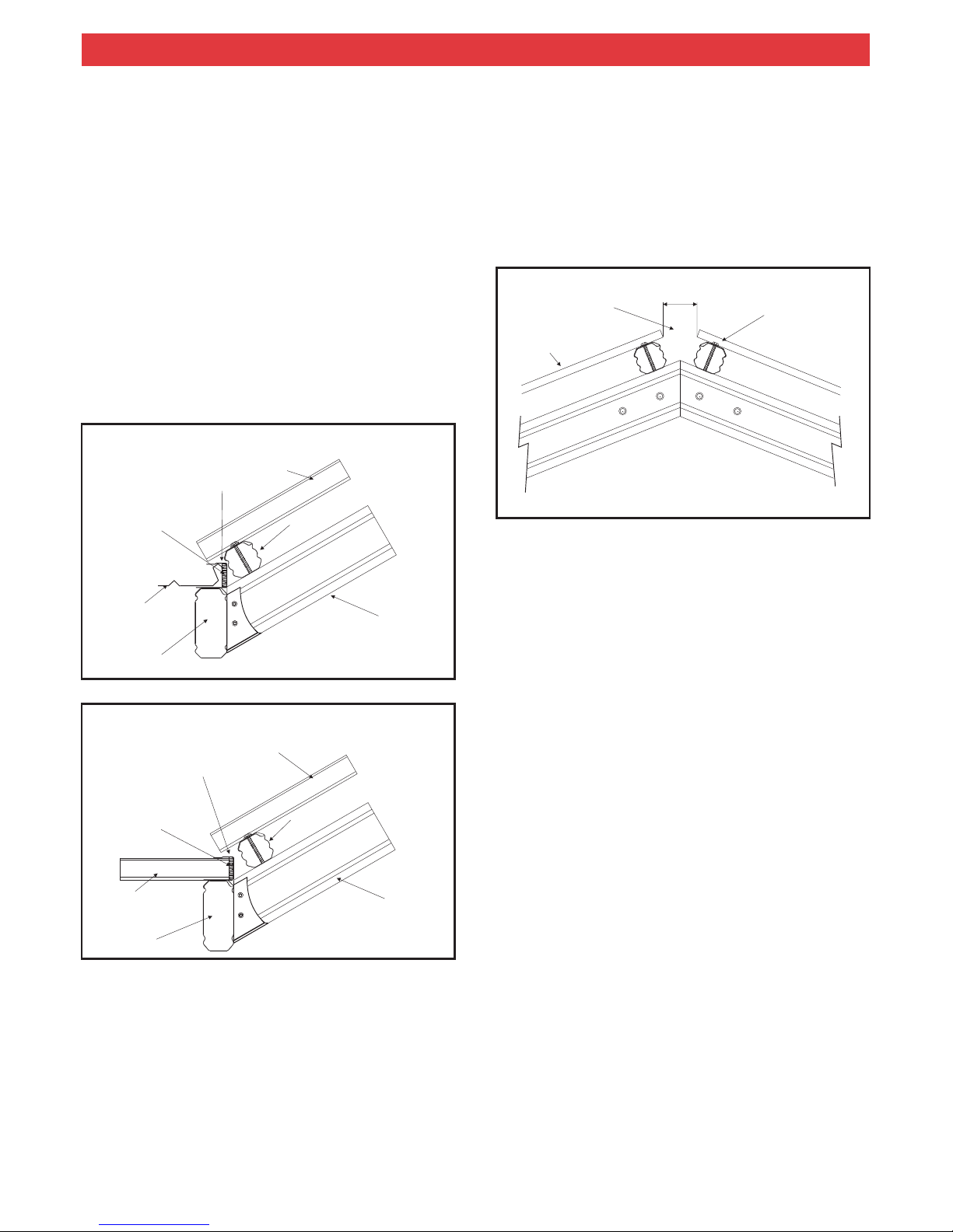
9.2 ATTACHING PURLINS
Where purlins are continuous over rafters they are fixed in
position using 14x95 hex head self drilling screws. If it is
necessary for purlins to be broken over standard gable
frames (ie, purlins continue inthe same directionpast a join)
a 68mm in-line purlin connector is used.
By drilling pilot holes and screwing through the top of
the purlin before lifting it into position, the process of
screwing into the rafters is made easier. Pilot holes should
also be drilled through rafters at the fixing location.
In the case of purlin joins which occur over a gazebo hip
rafter an angled purlin connector will be required. Fix purlins
together using 12x20 hex head screws. A 14x95 hex head
self drilling screw is fastened through the connector to hold
purlins to the rafter (Figure 32). A gap will be noticed at the
lower edge of the purlin join but this will not be seen after
installation of the purlin intersection cover.
If purlins do not align (ie, lowest gazebo end purlins and
lowest gable purlins) they may be screwed directly into hip
rafters.
Note:
30
MAX 100 mm
50 mm
PURLIN
120 RAFTER
VALLEY
BEAM
RIDGE
(MAX)
13
PURLINS

14
Note: Purlin Intersection Caps are available as an optional
extra and can be used to fill the small gap between the purlin
and the template cut out. Caps are riveted to the side of the
purlin cover.
With the exception of Gazebo Ends with Outback
®
deck, hip
support flashings ( Figure 2) are secured directly over purlin
intersection covers to hide roof sheeting cuts. Fix the
flashing to purlins at each purlin junction using a single rivet
either side of the flashing.
Mitre hip support flashings at the apex for a neat finish.
Connect the gutter to the flat roof Outbacks as described in
Assemble the remaining framework of the verandah as per
the installation guide ‘Outback Flat Attached Verandahs,
Patios & Carports’.
Fix the posts, as describedin the instructionbrochure under
"COLUMNS AND FOOTINGS” or "ALTERNATIVE
FOOTING".
Note: All adjustable construction props are to be left in
position until decking is attached and concrete is set.
‘Outback Flat Attached Verandahs, Patios & Carports’.
Gutters will need to be mitred at the point the flat roof unit
meets the gable and around the front of the gazebo end.All
gutter joins are to be waterproofed with silicon.
Where there is no flat roofadjacent to the gable, thegutter is
attached with gutter straps and flat connecting strips which
are fixed to the valley beam. Cut the strip into sections and
rivet at 1000 mm intervals to the valley beam. Fix the gutter
to the strip with rivets as shownin figure 34.Once decking is
attached (Section 12.0) the gutter is secured to the roof
sheeting using gutter straps at maximum 1200mm
intervals. Gutter straps may need to be bent slightly so they
can be rivetted to the roof sheets. Waterproof rivets with
silicone.
The above method is also used to fix gutter around the front
of the gazebo perimeter beams.
®
10.0 REMAINING FRAME ASSEMBLY
11.0GUTTERING
33
14x95 HEX HEAD
SCREW
12x20 HEX HEAD
SCREWS
PURLIN
INTERSECTION
COVER
TEMPLATE
CUT OUT
PURLINS
HIP RAFTER
CONNECTION DETAIL
RIVET
STEEL STRIP RIVETTED AT
1000mm INTERVALS TO
VALLEY BEAM AND GUTTER
34
150 VALLEY
BEAM
GUTTER
120 RAFTER
32
RAFTER
PURLIN
PURLIN
PURLIN
CONNECTION
12x20 HEX HEAD
SCREWS
12x20 HEX HEAD
SCREWS
14x95 HEX HEAD
SCREWS
9.3 PURLIN INTERSECTION COVER
The purlin intersection covers are used to cover any gaps at
purlin joins and also to attach decking. The location of
purlins are to be marked along each side of the purlin
intersection cover and the cover is then cut with tin snips to
allow a tight fit over purlins. The template provided will allow
the cut shape to be marked on the cover at the location of
each purlin.
The purlin intersection cover is now riveted on either side to
the chamfer of the rafter, rivets are to be located a maximum
of 50mm from purlins on both the higher and lower sides
and at spacings of no more than 300mm (Figure 33)
Each cover should be mitred at the apex to finish flush with
the gazebo apex flashing.
.
UNIVERSAL
DECK STRAP
15
35
OUTBACK DECK RUNNING
PARALLEL TO 150 VALLEY BEAM
®
150 VALLEY BEAM
OUTBACK
DECK
®
BITUMEN IMPREGNATED
FOAM INSERT
BACK CHANNEL
(UPSIDE DOWN)
ROOFING
120 RAFTER
68 PURLIN
36
OUTBACK DECK RUNNING
PERPENDICULAR TO 150 VALLEY BEAM
®
150 VALLEY BEAM
OUTBACK
DECK
®
BITUMEN
IMPREGNATED
FOAM
BACK CHANNEL
(UPSIDE DOWN)
ROOFING
120 RAFTER
68 PURLIN
12.2 MULTISPAN GABLE
When attaching the decking to the gable, start from the rear
(non gazebo end) on one side of the gable, aligning the
sheets so as to avoid the purlin fixing screws.
If the deck of the flat roof section runs perpendicular to the
valley beams, align the ribs of the gable decking up with the
flat roof section. Fix the decking so thatit is level with the top
of the flat deck, and so there is a maximum 100 mm gap at
the ridge (Figure 37).
37
POLYCARBONATE
OR CGI
ROOF SHEET
NO BACK
CHANNEL
REQUIRED
PURLIN
FIXING SCREW
MAX
100 MM
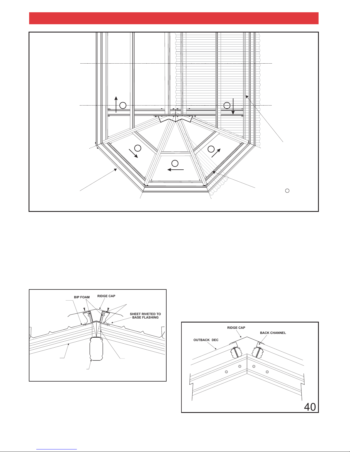
12.3 GAZEBO END
At the point when less than one full sheet is required to pass
the centreline of the front gable frame on one side, the
Gazebo End decking will need to be cut to suit. Refer to
figure 39 for cutting order and laying direction.
Continue laying deck past the end gable frame (Section 1,
Figure 39) and cut the sheeting along the centreline of the
purlin intersection cover. The offcuts from this section are
used in section 2 but deck is layed in the opposite direction
as shown by the arrow in figure 39. When all offcuts are
utilised begin with new sheeting.
This process is continued around the front of the Gazebo
End and back down the side of the Multispan Gable (i.e.
Offcuts from section 2 are used in section 3 with deck being
layed in the direction shown in figure 39, offcuts from
section 3 are used in section 4 and so on).
The centreline of the purlin intersection covers are
used to mark the sheets for cutting. Sheets are to be taken
down from the framework to be cut. It is recommended
sheeting is supported in a horizontal plane off the ground at
a comfortable height for cutting.
All sheeting which ends at the apex is to be cut to a point so
it meets directly above the centre of the end gable frame.
Gazebo end decking will need to overhang the last purlin
and gazebo fascia beams allowing water to flow directly
into the gutter (Figure 34). It may be necessary to notch the
top of the backchannel on the valley beams to avoid
interference with roof sheets at the first gazebo corner.
The edge of roof sheeting, running along hips, is to be fixed
through the hip support flashing and into the purlin
intersection cover.
Note:
12.0 ATTACH DECKING
12.1 FLAT ROOF
Attach the decking to the flat roof verandah first as laid out
under "THE DECKING" (‘Outback Flat Attached
Verandahs, Patios & Carports’), starting from the valley
beam and working away, on both sides.
The back channel is attached upside down (the shorter leg
on top) along valley beams to assist the fixing of decking.
(Figures 35 and 36). The channel extends to the end of the
valley beams.
Figure 35 shows the back channel and Outback deck
running parallel fixed to a 150 valley beam. Figure 36
shows the back channel and Outback deck running
perpendicular to a 150 valley beam.
®
®
When using polycarbonate or corrugated roofing no back
channel is required at the ridge. When Outback deck is
used, back channel is required at the ridge, and is supplied
with the unit (Figure 40).
Two piece back channel is required at the ridge. When
Outback deck is used, back channel is required at the
ridge, and is supplied with the unit (Figure 40).
®
®
16
39
12.3.1 OUTBACK DECK
®
For Outback deck a special two piece backchannel will be
required and is to be located along the purlin cover before
the decking is fastened in place (Figure 38). The flashings
are screwed to the purlin cover using 12x20 hex head
screws at 500mm centres on alternating sides of the
shallow ridge. Outback deck is riveted to the base flashing
at 250mm centres
®
®
.
For Outback deck slide back channel over the ridge end of
the deck and rivet into place. Position the ridge cap over the
two back channels and screw or rivet into the channel
(Figure 40).
For polycarbonate and corrugated roofing screw or rivet
(depending on ridge cap style) the ridge cap directly onto
the top of the deck. Waterproof rivets with silicone.
Do not rivet to polycarbonate decking, screw only.
®
Note:
13.0 RIDGE CAPPING
13.1 MAIN RIDGE
3
2
1
DECKING
GAZEBO END
4
5
OFFCUT FROM SECTION 1
TWO PIECE BACK
CHANNEL
OUTBACK DECK
®
38
PURLIN
HIP RAFTER
PURLIN COVER
aaaa
aaaa
aaaa
aaaa
aaaa
aaaa
aaaa
aaaa
aaaa
aaaa
aaaa
aaaa
aaaa
aaaa
aaaa
aaaa
aaaa
aaaa
BIP FOAM
SHEET RIVETED TO
BASE FLASHING
RIDGE CAP
40
BACK CHANNEL
RIDGE CAP
OUTBACK DECK
®

17
14.1 HEADER BEAM WITHGUTTER
Attach the header flashing to the rear gutter lip with rivets.
Infill panels are fixed through the top groove of rafters and
the end strut with 8x35mm self embedding teks at 500mm
centres in non-cyclonic areas and 250mm centres in
cyclonic areas. Panels are fixed at the base through the
header flashing with split tail soft pull rivets at 500mm
centres (Figure 43).
INFILL PANEL
43
GUTTER
HEADER FLASHING
SPLIT TAIL SOFT
PULL RIVETS
HEADER BEAM
14.0 INFILL PANELS
Two styles of header flashings are available to neatly finish
the base of infill panels, one is used on header beams with
gutter and the other for headers without gutter. Gable infill
panels are to be cutin triangular shapesto fit theend frame.
Panels can be painted to the desired colour before
installing.
End struts are fixed mid-span of the header to a header
beam bracket at the base and an end strut plate at the ridge
(Figure 42).
HEADER BEAM
INFILL PANEL
44
8x35mm SELF
EMBEDDING TEK
10x16 HEX HEAD SELF
DRILLING SCREWS
HEADER FLASHING
15.0 ATTACHING BARGE CAPPING
If barge capping is required at the opposite end to the
gazebo, attach the barge cap by screwing the lower lip to
the rafter and screw the top sectionto the purlin throughthe
deck, as shown in figure 45. Mitre the barge at the apex of
the gable for a neat finish. Run the barge cap along the
gable section to where it meets the flat verandah deck and
finish neatly.
If infill panels have been installed, the lower lip of the barge
capping should cover the panel screws to give a neat finish.
14.2 HEADER BEAM WITHOUTGUTTER
Infill panels are fixed through the top groove of rafters and
the lower groove of the header beam with 8x35mm self
embedding teks. Fix at 500mm centres in non-cyclonic
areas and 250mm centres in cyclonic areas. Panels are
fixed to the end strut at the same spacings. Attach the
header flashing to the underside of the header beam with
10x16 hex head screws to neatly finish the base of the infill
panels (Figure 44).
42
FIX TO FRONT OF RIDGE
WITH 2 12x20 HEX HEAD
SELF DRILLING SCREWS
FIX TO STRUT WITH
2 10x16 HEX HEAD SELF
DRILLING SCREWS
FIX STRUT TO BRACKET
WITH 2 10x16 HEX HEAD
SELF DRILLING SCREWS
EITHER SIDE
FIX BRACKET TO HEADER
WITH 2 10x16 HEX HEAD
SELF DRILLING SCREWS
13.2 GAZEBO END CAPPING
Ridge cap is also used over all gazebo end rafters to
conceal the line in the deck.
For Outback deck a special
back channel is required andshould have been installedas
described in section 12.3.1. The ridge cap is positioned
over the channels and screwed in place through the
channels (Figure 38). For Polycarbonate and corrugated
decking the cap is screwed directly to the top of the deck.
Ridge capping will need to be cut to meet a point at the
apex as detailed in figure 41. Allow an approximate 20mm
overlap at the ridge. The capping isto be fully siliconsealed
at the apex for waterproofing.
®
41
20mm OVERLAP
FRONT GABLE FRAME
RIDGE CAPPING

18
16.0 HELPFUL TIPS
Leave plastic coating on members until they are about to
be fastened to the structure. This will help prevent
scratching of the coloured finish.
Sweep the roof and clean gutters after the completion of
work. Ensure any swarf and rivet stubs are removed as
they can cause unsightly rust stains.
Do not allow soil to remain in permanent contact with the
columns, as corrosion will result in the base of the
column. Refer to the “Selection, Use and Maintenance of
Stratco Steel Products” brochure for complete details of
the maintenance requirements.
Double check all measurements and drilling locations
before proceeding.
Regularly check framework for squareness and vertical
alignment to make sure it hasn't moved during
construction.
Purlin Overhang
BARGE CAP
RIVET
RAFTER
ROOFING
14 x 95 HEX HEAD
SELF DRILLING SCREWS
PURLIN
No Purlin Overhang
BARGE CAP
12x35mm ROOFING
SCREWS
END OF
PURLIN INLINE WITH
RAFTER CHAMFER
RAFTER
ROOFING
14 x 95 HEX HEAD
SELF DRILLING SCREWS
PURLIN
ATTACH THROUGH
DECK AND PURLIN
ATTACH THROUGH
DECK AND PURLIN
45
 Loading...