

Stratco CLICKFAST FASCIA AND GUTTER SYSTEM, CLICKFAST FASCIA, CLICKFAST GUTTER SYSTEM User Manual

The Clickfast Fascia and Gutter
System was originally designed
by Stratco and has proven to
be the most successful fascia
and gutter system in Australia
using a flat steel fascia.
It has been used successfully
by major builders for more than
20 years and remains the
industry leader. It is one of the
few products in Australia to receive the coveted
"classic" design award. In addition to design
excellence, this also guarantees a friendly, tried and
usable system for the Installer.
HOW TO USE THIS MANUAL
Before attempting to install the Clickfast Fascia and
Gutter system to a new home, you should read the
Clickfast Fascia and Gutter brochure and also this
installation manual completely. If further advice is
required, contact your nearest Stratco sales office.
185MM FLAT FASCIA
This fascia is a non structural component designed to cover the end of rafters, provide support for the gutter
and is suitable to support a 4.5mm or 6mm soffit lining placed horizontally, or a 4.5mm soffit raked up to 15˚.
STANDARD RAFTER BRACKET
This bracket supports the fascia and is nailed to the side of each rafter.
HIP RAFTER BRACKET
This bracket is bent at 45˚ and is used on hip rafters to provide a strong external corner.
EXTERNAL MITRE
These are fitted on the outside of the fascia for all 90˚ external corners. The ribs in the mitre continue the
smooth line of the fascia around external corners.
INTERNAL MITRE
After the fascia has been formed around an internal corner, this component is simply riveted to the underside
of the fascia.
JOINING SLEEVE
This component is fixed internally, joining two longer lengths of fascia together. It provides the ideal method of
joining two lengths.
BARGE RAFTER BRACKET
This is used to support the fascia when it is being used as a barge. The top of the bracket is recessed to allow
the barge gutter to sit neatly.
SUSPENSION CLIPS
These clips are a specially designed clip made of spring steel and are placed at approximately 1.2 metre
intervals along the fascia. It allows an adequate fall to be given to the gutter.
BARGE APEX COVER
This cover enables the apex of two joining barges to be joined neatly.
BARGE MOULD (specify left or right hand)
These are used to provide a neat corner where the fascia and barge meets. The ribs on the barge mould
allow a smooth flowing line to run along the fascia and continue neatly up the barge. They must be ordered as left
or right hand. The long face of the barge mould runs along the fascia.
BARGE GUTTER
This specially manufactured gutter fits over the top of the barge and is supported by timber outriggers. It
allows the small amount of water which falls between the last tile and the fascia to run to the gutter.
INTRODUCING THE CLICKFAST® FASCIA AND GUTTER SYSTEM
COMPONENTS OF THE CLICKFAST® FASCIA AND GUTTER SYSTEM
1: 185MM FLAT FASCIA
2: STANDARD RAFTER BRACKET
3: HIP RAFTER BRACKET 4: EXTERNAL MITRE
5: INTERNAL MITRE
9: BARGE APEX COVER 10: BARGE MOULD 11: BARGE GUTTER
6: JOINING SLEEVE 8: SUSPENSION CLIP
7: BARGE RAFTER BRACKET
1
2
3
4
5
6
7
8
9
10
11

EAVES & VERGE CONSTRUCTION
TILE ROOFS
BARGE GUTTER
FASCIA(AS BARGE)
TILE
OUTSIDE WALL
LINING
TRIMMER
RAFTER
TILE BATTENS
OUTRIGGER
FASCIA
To ensure that your barges perform as required, it is important that thought has been given to the correct
layout of roof framing for this area. Outriggers are generally required to support the weight of roofing
extending past the wall line. The following details show how these trimmers should be installed:
NOTE:
A roof purlin should
be placed
approximately
75mm from the top
of the fascia to
support the end of
the roofing sheet.
ARCHITECTS NOTE:
A 185mm fascia is generally suitable for the majority of standard house designs and
eaves & verge styles. In some cases variations in rafter depth and roof pitch will
require a fascia extension. This can simply be riveted to the top of the standard
fascia. Contact Stratco for details.
VERGE FRAMING
1
2
3
TRIMMER
TILE BATTENS
OUTRIGGER
1
1
2
3
3
2
3
3
1
2
3
4
5
6
7
8
9
10
1
2
3
4
5
6
7
8
9
10
SHEETMETAL ROOFS

MARKING OUT TOOLS
TOOLS YOU WILL NEED
INSTALLING FASCIA
Square, string line, adjustable
bevel square & spirit level.
CUTTING TOOLS
Hacksaw, snips.
FIXING TOOLS
Hammer, drill, silicone, rivet gun
pliers.
OTHER USEFUL ACCESSORIES
Ladder, scaffold.
MEASURING YOUR PROJECT
Draw your roof outline and measure each fascia
length required, marking it on your plan.
For lengths longer than 9 metres, allow a joining
point adjacent to one rafter and mark the adjusted
fascia lengths on your plan.
BEFORE YOU START
Ensure that all materials are on site and double check
that the materials delivered correspond with your
order and initial take-off. Ensure that all tools are on
hand and that you have completely read and
understood the Clickfast Fascia and Gutter
installation instructions.
If further advice is needed contact your nearest
Stratco Sales Office before commencing.
MARKING OUT
Check rafter foot and plumb cuts are correct.
Determine the eave height, by reference to the
plans and by the location of soffit supports. The
soffit should finish at the top of the window reveal,
unless otherwise specified and the distance from the
top of the top plate to the window reveal should be
recorded (measurement A). Generally, this
measurement should only be taken from the highest
windows (usually the WC, laundry or bathroom).
Check at least two windows to confirm the height.
Determine the distance from the back of the fascia
base (by using a rafter bracket) to the outside
face of the wall frame (measurement B). It is
important to use a spirit level to ensure that the
bracket is plumb in taking this measurement.
Measure barges by taking the actual roof length
from the top of the apex to the bottom of the
proposed fascia. Allow 300mm extra for laps and
angle cutting.
1
4
Deduct 60mm from measurement Aand 50mm
from measurement B to provide two mark out
points for setting out a bracket. The mark out points
determine the back of the bracket and the centre slot.
4
Using an adjustable bevel square, spirit level and
tape, mark the bracket location on the second
last rafter from each end of a fascia run. Nail a
bracket (commencing with the first nail in the
adjustment slot) to the inside of each rafter. Fully nail
off each bracket with three nails.
5
1
2
3
Place a nail into the
foot cut of the rafter
on the two brackets from
Step 5, on the
measurement B-50mm
line and run a taut string
line between them.
6
Using a bevel square,
mark the location for the
back of the bracket on
every second rafter. Repeat
this process around the
building.
NOTE: An alternative
method is to put the string
line on the inside of the
soffit groove on the bracket.
To mark out the remaining
brackets, use a loose
bracket and the bevel
square in conjunction with
the string line. Afinal check
is made using a spirit level
against the bracket.
7
Complete your order form by summarising all
fascia and barge lengths, counting internal and
external mitres, and listing the number of brackets
and other accessories required.
Phone or fax your order to your nearest Stratco
outlet, clearly specifying delivery details and the
fascia and gutter finishes required.
5
6
For internal corners not using butt joint method,
measure past the corner (approximately 1 metre,
and adjacent to a rafter) and mark the adjusted
lengths on your plan. If the butt joint method is used
lengths are measured to the actual corner.
3
2

INSTALLING ACCESSORIES
INSTALLING FASCIA AS BARGE
FASCIA INSTALLATION
Slide the fascia onto one of the two brackets fixed
(see 5 above).
▫ Clip the base of the fascia into the second bracket.
▫ Stretch the top of the fascia over the top of the
bracket. In some cases, fascia can be simply slid
over the second bracket.
At the centre point of the run, insert a bracket into
the fascia and then fix the bracket to the set up
point previously marked (Step 7 previous page) with
a nail in the centre slot only.
Check the fascia for straightness (by eye) by
looking along the base of the fascia (also check
with spirit level to base of fascia). When straight, fix
every second rafter to the set up lines marked, again
using the centre slot and now utilizing one of the
base holes. Ensure that the base of the fascia
stays straight.
1
MARKING OUT
On the barge rafter bracket, the centre slot is set
52 mm from the base of the outrigger and the
back of the bracket is set in 50 mm from its end.
FIXING BRACKETS
Fix only two brackets as previously described
using three nails on each side of gable.
INSTALLING
The first length of barge to be installed must first
have the lower end made to fit the fascia.
This is done by:
▫ Marking on the front of the
barge the roof pitch and then cut
off.
▫ On the cut edge, mark down
185 mm, and then draw a line at
90˚ from the base to intersect this
point, then cut this off.
▫ On the cut edge, mark a line at
90˚ at the intersection of the two
previous steps. This line will go to
the base of the fascia.
▫ Cut along the line marked in the
previous step. Also cut excess
metal from below soffit groove
(trim this groove to length if
needed). Push upwards and rivet.
Attach barge as previously described for fascia.
Attach barge mould as per external mitre (remember that the long leg of the barge mould fits on the
fascia. Both left hand and right hand barge moulds are available).
Install remaining barge rafter brackets.
1
1
1
2
3
4
JOINING SLEEVES
Where a joining sleeve is required, do not fully
nail standard rafter brackets for at least two
rafters adjacent to the join.
Rivet the joining sleeve to one length of fascia
as shown.
1
2
Slide the second piece of fascia over the joining
sleeve and rivet.
Check that the fascia is straight by sighting
along the base of the fascia and nail the
remaining brackets.
3
4
EXTERNAL MITRES
Slide the external mitre over the adjoining fascia
and check that the fascia has not been pulled out
of line and that the corner remains square.
Rivet the external mitre at the 'dimples' embossed
in the mitre. Recheck for square and alignment.
1
2
2
3
INTERNAL MITRES
Measure the fascia from the inside of the nearest
external corner or joining sleeve to the proposed
position of the internal mitre.
Cut the top lip of the fascia and the base with a
hacksaw and bend to 90˚.
Fix the fascia to the brackets on the long run in
the same manner as previously described.
Ensuring that the internal corner remains at 90˚,
fix the rafter brackets to the short run of fascia.
Attach the internal corner with rivets as shown.
Note that the alternate butt joint method still
requires an internal corner mitre.
1
2
3
5
4
Finish nailing all marked brackets and then all
brackets not previously installed.
Install hip rafter brackets remembering to fold the
top tag over the rafter and nail.
4
5
52mm
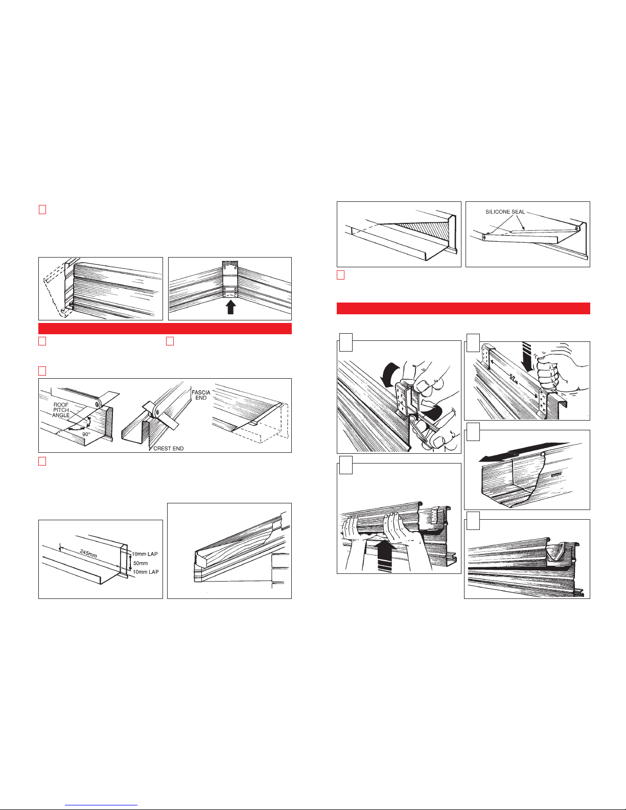
PREPARING AND INSTALLING BARGE GUTTER
CLICKFAST®GUTTER INSTALLATION
Cut barge vertically at apex. The second length of
barge to be put up is done in a reverse manner.
This is done by:
▫ Cut barge vertically to suit apex on the ground.
▫ Install barge as per previous length.
▫ Mark length against fascia.
▫ Remove the second piece of barge.
▫ Modify end to suit fascia as per previous length.
▫ Re-install barge.
▫ Attach barge mould as per previous.
▫ Install remaining barge rafter brackets.
▫ Install barge apex cover by pushing up from
bottom, rivet to barge and trim excess.
5
On the apex end of your barge gutter, set an
adjustable bevel to the roof pitch, mark a line up
the front of the barge gutter, continue the line over
the crest of the gutter, across the pan and up the
short side, again using the roof pitch.
Cut along the lines to remove the excess
material.
1
2
Repeat the above process, drawing a second line
10mm from the cutting line, this allows a lap to
join the two lengths together at the apex later.
(This length has a joining line marked on it).
3
Measure the barge from the apex cut to the
outside edge of the fascia.
NOTE: Where your barge gutter reaches the eaves
gutter, the barge gutter is below the level of the back
of the eaves gutter. To rectify this simply follow these
steps.
▫ From the base of the barge gutter, allow a 10mm
lap then mark a second line 50mm above the first
(note: make sure to leave at least 10mm from the top
edge to join together).
To maintain a downward water flow to the gutter:
▫ Mark and cut as shown in the drawing.
▫ Fold the base up and rivet and silicone joints.
Please note that the vertical edge may need to be
trimmed to suit tiles.
▫ Repeat for remaining lengths.
4
Install the first length of barge gutter (that has
no allowance for joining at the apex) ensuring it
sits parallel to the barge.
▫ Rivet the barge gutter to the barge at
approximately 900mm centres just above the rib.
NOTE: Most gutter profiles produced by other manufacturers cannot be used in conjunction with the Stratco
suspension clip.
▫ Install the second length of barge gutter and at the
apex, where the two lengths meet, bend the laps
down to meet the first length of barge gutter, rivet
and seal.
5
In the middle of a run of gutter and fascia,
two suspension clips are installed onto the
fascia, approximately 1200mm apart.
1
NOTE: When joining gutter lengths, always
make sure that the water flow runs down
the lap.
4
Internal gutter straps are rolled into the front
bead and then bent over the back of the
fascia. These are also placed at approximately
1200mm spacing.
5
The gutter is lifted until the suspension clip
engages the back of the gutter to hold it in
position.
Falling the gutter to the water outlets is achieved
by “clicking” the gutter up to the top tooth at the
point furthest away and to the second lowest tooth
near the water outlet.
3
2
 Loading...